
Fix mistakes with a "spring loaded butterfly valve" by checking fail action, complete-stroke torque, supply and exhaust paths, materials, and installed clearance. The assembly uses stored spring energy for a specified return movement. If a valve shuts a cooling path or stays open on a tank fill line, review the complete valve, actuator, and control sequence before approval.
1. What does a spring loaded butterfly valve do?
A spring loaded butterfly valve returns toward a defined end position through a spring mechanism connected to its shaft. In common pneumatic assemblies, air moves the actuator against its springs and an exhaust path allows the springs to drive the return stroke. Some manually operated handles and electric actuators also store spring energy. These arrangements have different controls, torque curves, and operating limits.
State which arrangement you need on the inquiry rather than leaving the word spring to describe the entire package.
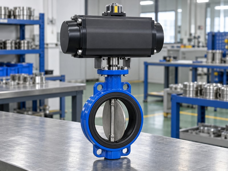
Identify the source of the return force
Check the assembly drawing and operating instructions before interpreting a product photograph. A rectangular actuator housing can contain different internal configurations. A spring-assisted check valve also has a different job: its disc responds to flow reversal rather than a commanded quarter-turn shaft movement. On a butterfly valve, the process disc remains in the passage when open.
Its position, seat contact, and flow resistance still need review even when the spring-return mechanism works correctly.
- Identify pneumatic, electric, or manual operation.
- Record the spring-driven direction and full travel.
| Arrangement | Normal operating force | Return condition |
|---|---|---|
| Pneumatic | Compressed air | Air chamber exhausts |
| Manual | Operator effort | Operator releases handle |
| Electric mechanical return | Motor | Specified release condition |
2. Which fail position does your process need?
The required fail position of a spring loaded butterfly valve comes from the process response to each failure. Closing can stop gravity-fed liquid entering a tank. Opening may preserve a cooling path when the supply arrangement supports that action. Neither example establishes the correct position for another line.
Write separate responses for loss of air, loss of electrical power, loss of control signal, and restoration of utilities. Include upstream and downstream equipment in that review.
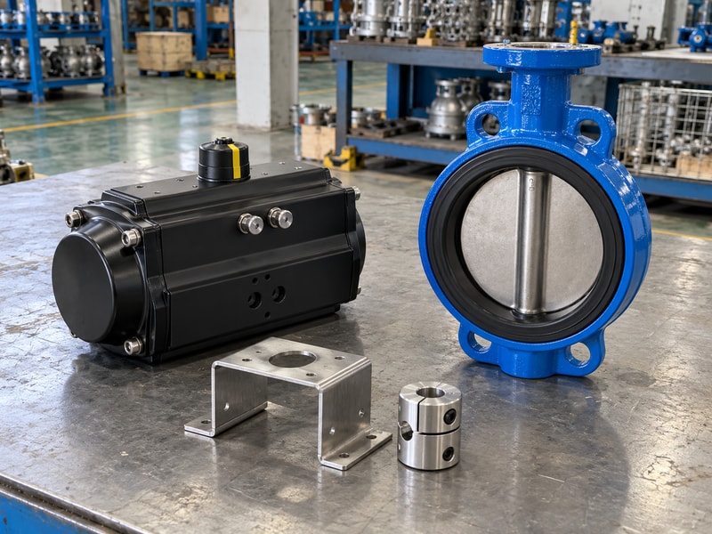
Separate an electrical trip from air loss
An electrical trip normally changes the solenoid state. Whether the actuator returns depends on the resulting pneumatic path, trapped pressure, and mechanical configuration. A closed upstream air valve can leave pressure trapped in an actuator chamber. An electrical interlock can also demand a different action from a complete loss of utilities.
Confirm the valve disc reaches the agreed position under each specified test condition. A control-system icon or an energized coil alone cannot establish that result.
- Define the safe position with the process designer.
- List restart behavior and reset conditions.
| Event | Question to resolve |
|---|---|
| Air supply loss | Can trapped air escape through the intended route? |
| Electrical loss | What state does the solenoid adopt? |
| Utility restoration | Does the valve restart automatically or require reset? |
3. How do you check spring torque through the stroke?
Check a spring loaded butterfly valve by comparing available actuator torque with required valve torque throughout travel. The air-driven and spring-driven strokes need separate comparisons. Breakaway, running, and seating torque can differ with differential pressure, temperature, seat material, and time spent closed. Use data for the actual valve size and configuration.
A single maximum actuator torque printed on a quotation does not show whether the weakest part of the return stroke can complete closure.
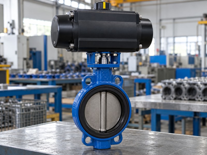
Keep valve and actuator curves together
Ask for the actuator output curve at the minimum pressure available while the valve moves. Then compare the spring curve with the valve load in the intended return direction. Include the manufacturer's sizing allowance and check the permitted shaft, bracket, and coupling torque. A larger actuator can exceed an interface limit.
For a proposed spring loaded butterfly valve, keep those limits on the same approval sheet as the torque comparison so a later substitution does not lose them.
- Use maximum specified closing differential pressure.
- Check output limits as well as torque reserve.
| Data | Required basis |
|---|---|
| Valve load | Actual size, seat, temperature, and differential pressure |
| Air stroke | Minimum dynamic air pressure |
| Spring stroke | Output across the complete return travel |
4. What air supply and exhaust checks prevent slow return?
A spring loaded butterfly valve needs both adequate supply during its air stroke and an effective exhaust path during return. Check pressure at the actuator while it moves, rather than relying on a compressor-room gauge. Filters, regulators, solenoid passages, tubing, and exhaust accessories influence the available flow. Dirty or blocked exhaust hardware can delay the return stroke even when the spring pack is correctly sized.
Specify clean air and ambient limits from the actuator instructions.
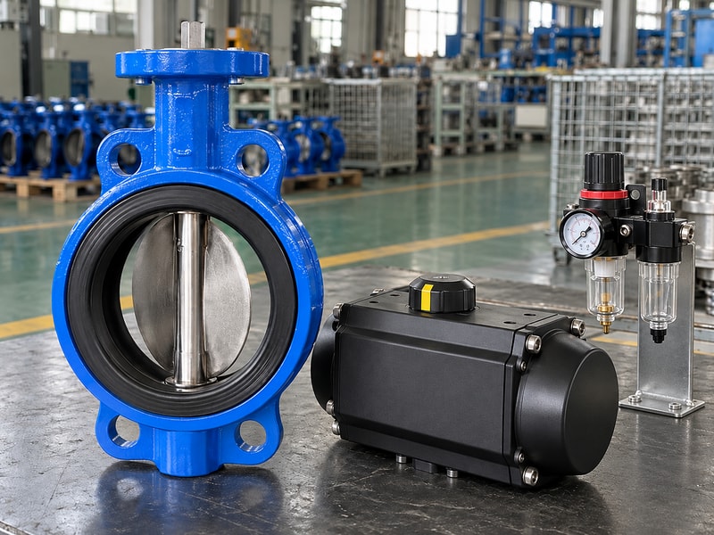
Measure travel under the intended conditions
Record the operating pressure, control state, stroke time, and end-position indication during an agreed test. If the return slows, investigate external restrictions and mechanical resistance before changing a spring pack. Flow-control accessories must suit the actuator's return arrangement and the required timing. Set closing speed with the piping transient assessment in view.
A fast stroke can create an unacceptable pressure change in a liquid line, while a slow stroke may fail the process shutdown requirement.
- Locate restrictions on the actual supply and exhaust paths.
- Retain the approved speed settings in the handover record.
| Observation | Check next |
|---|---|
| Pressure falls during motion | Supply capacity and regulator setting |
| Return starts late | Solenoid state and exhaust restriction |
| Disc movement becomes uneven | Mechanical load, alignment, and seat condition |
5. How do body connections affect actuator performance?
Body connections affect a spring loaded butterfly valve when flange misalignment or inadequate disc clearance adds resistance. A wafer body fits between matched pipe flanges. A lug body uses its specified threaded connections. A double-flanged body has its own face-to-face and drilling arrangement.
Confirm the actual mating bore, gasket arrangement, bolt engagement, and opening envelope before installation. Pipe supports must carry piping loads so the valve and actuator mounting do not become improvised supports.
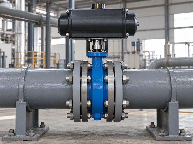
Check the installed opening envelope
A disc can project beyond the valve face as it opens. Nearby liners, reducers, gaskets, or pipe bores can obstruct that movement. Resolve the interference from drawings before attempting a powered stroke. Review a spring loaded butterfly valve with its mating flange details, since a compatible nominal pipe size alone does not prove clearance.
End-of-line use also needs the valve manufacturer's specific approval, pressure direction, and fastening arrangement; a lug body does not establish that qualification by itself.
- Verify disc clearance across the full travel.
- Use the approved bolt and gasket arrangement.
| Interface | Evidence to check |
|---|---|
| Pipe flange | Drilling, face, bore, and rating |
| Disc envelope | Clearance drawing at full opening |
| Actuator mounting | Aligned shaft, bracket, and coupling dimensions |
6. Which materials suit the actual fluid and temperature?
Select spring loaded butterfly valve materials from the complete fluid composition and simultaneous pressure-temperature conditions. Seat, disc, shaft, auxiliary seals, coating, and any liner all need review. An EPDM water configuration does not establish suitability for an industrial oil. Stainless steel alone does not establish suitability for seawater or every chemical liquid.
Ask for the exact material and compound identification, including additives or cleaning fluids that contact the assembly during service.
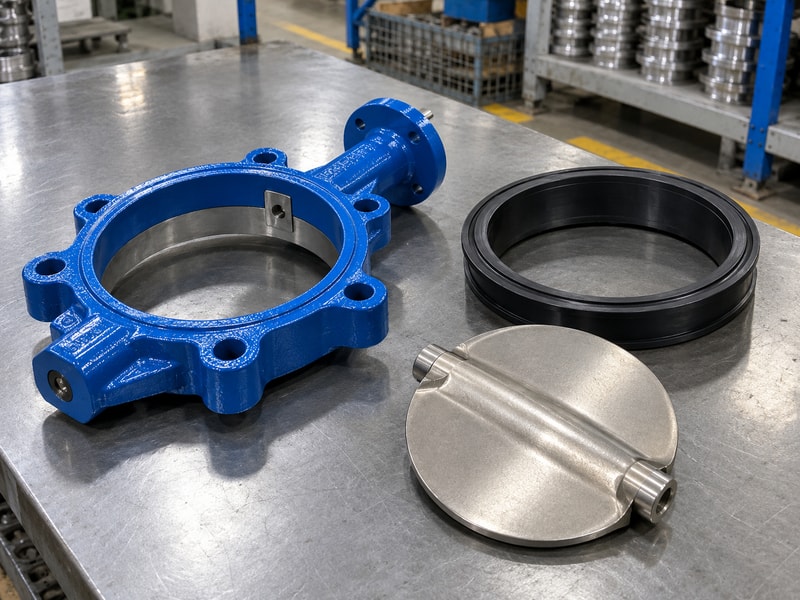
Keep pressure tests separate from service ratings
Use the allowable working pressure at the specified temperature, together with the permitted disc closing differential pressure. A shell test pressure is an inspection input and cannot replace either limit. RUITO's product information treats water, mineral oil, clean gas, seawater, and lined chemical configurations separately. For a lined butterfly valve, review the continuous wetted barrier, backing, shaft seals, and vacuum limits as one configuration.
A lining material name by itself leaves several possible leakage or damage paths unresolved.
- Provide fluid concentration and cleaning conditions.
- Confirm ratings for the exact assembled configuration.
| Service input | Selection consequence |
|---|---|
| Actual fluid formulation | Seat, auxiliary seal, and metal compatibility |
| Operating temperature | Material limits and pressure derating |
| Low absolute pressure | Liner retention and vacuum-specific review |
7. What can position feedback prove?
Position feedback on a spring loaded butterfly valve can report an adjusted shaft or actuator position. It does not directly measure seat leakage. A loose coupling can separate actuator motion from disc travel, and an incorrectly adjusted switch can report the wrong endpoint. Inspect the mechanical connection and verify feedback against actual valve movement during commissioning.
Keep the electrical indication test and the specified shutoff leakage test as separate acceptance items.
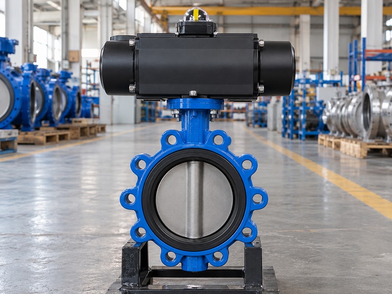
Define feedback and trip signals precisely
List the required open and closed contacts, signal type, enclosure conditions, cable entries, and control-system interpretation. A mechanical indicator is useful locally but still needs correct alignment. If the process requires a safety function, the complete arrangement needs its specified assessment and proof-test procedure. A spring-return actuator, limit switch, or product certificate alone does not establish the performance of an entire safety function.
Record the test boundary so later maintenance personnel know what the original check covered.
- Verify indication with the installed coupling.
- Specify independent leakage acceptance where required.
| Check | What it establishes |
|---|---|
| Position contact test | Contact changes at the agreed mechanical position |
| Return travel test | Assembly reaches the specified endpoint under test conditions |
| Seat leakage test | Leakage meets the selected procedure and criterion |
8. How should you inspect and maintain the assembly?
Inspect a spring loaded butterfly valve using its manufacturer's isolation and stored-energy procedure. Remove process pressure and control the possibility of automatic movement before working near the disc or coupling. An actuator can retain spring energy after electrical power and air have been removed. Keep spring housings closed unless an authorized maintenance procedure specifically covers their disassembly.
The maintenance interval should reflect duty, environment, inspection findings, and the process requirement rather than a generic calendar claim.
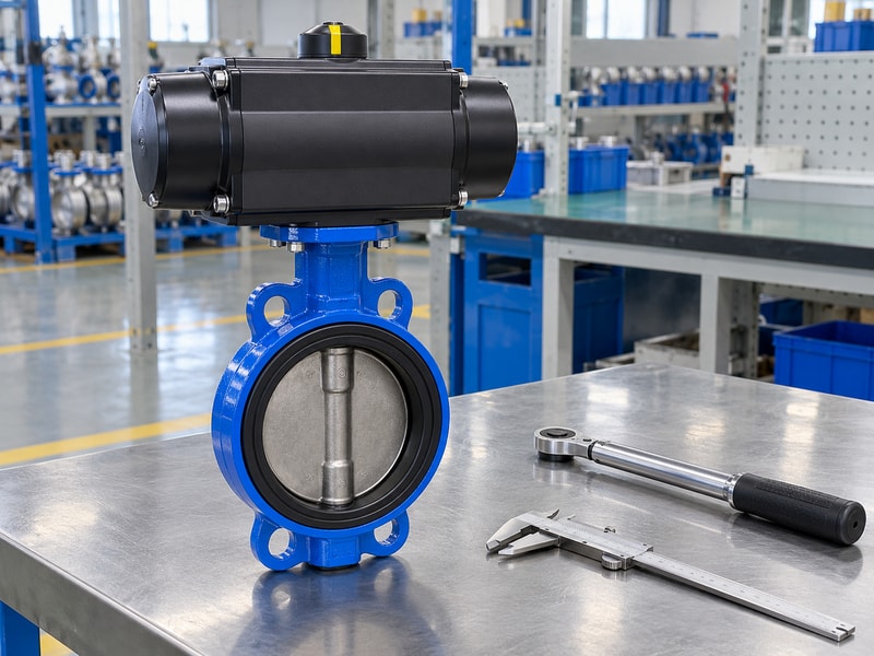
Use changes in behavior as inspection evidence
Track return time, air pressure during movement, switch timing, external leakage, corrosion, and mounting condition against the commissioning record. A growing difference can point toward restriction, seal friction, coupling wear, or actuator deterioration. Investigate the cause before increasing air pressure or changing mechanical stops. After replacing a seat or actuator, repeat the affected sizing, alignment, return, and leakage checks.
The replacement may change operating torque even if its nominal size and external appearance match.
- Keep hands and tools outside the disc travel zone.
- Retain the original baseline and maintenance findings.
| Change | Action |
|---|---|
| Longer return time | Review exhaust path and mechanical resistance |
| New external leakage | Isolate and inspect the relevant sealing system |
| Replacement component | Reconfirm matching data and affected acceptance tests |
9. What should your purchase specification include?
A spring loaded butterfly valve purchase specification should define the duty, complete assembly, failure responses, and evidence required for acceptance. Include nominal size, connection details, actual fluid, temperature, pressure, differential pressure, cycling frequency, and installation conditions. State the air or electrical supply, spring-driven position, operating times, feedback, and manual override arrangement. Require a clear distinction between the offered configuration and any optional features that have not been included in the price.
Make substitutions reviewable before shipment
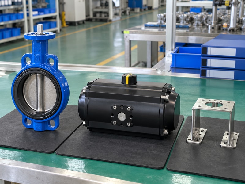
Ask the supplier to identify the valve, actuator, bracket, coupling, controls, and seal configuration on one assembly record. Request the corresponding drawing, sizing calculation, operating instructions, and agreed test reports. Dimensional interchangeability does not establish matching return torque or the same failure response. Identify who must approve substitutions and which tests must be repeated.
Send RUITO the service data and required failure sequence so the proposed package can be reviewed against a defined duty before manufacture or dispatch.
- List required documents and acceptance conditions.
- Approve configuration changes before they reach the site.
| Purchase item | Required deliverable |
|---|---|
| Mechanical assembly | Approved drawing and material identification |
| Operating duty | Valve load and actuator sizing basis |
| Acceptance | Return-function, feedback, and specified leakage records |
10. What should buyers check before approving a valve?
Q1. Can I assume every spring-return valve fails closed?
No. The spring-driven position depends on the actuator configuration, mounting relationship, and control arrangement. Specify open or closed for each failure condition and verify the complete assembly under the agreed test conditions.
Q2. How do I know if the actuator has enough torque?
Compare the valve load with available output through both strokes. Use the actual seat, temperature, differential pressure, minimum moving air pressure, sizing allowance, and interface torque limits.
Q3. Can I replace a double-acting actuator with a spring-return unit?
Only after reviewing the complete package. Mounting compatibility, spring and air torque, solenoid plumbing, supply capacity, failure position, stroke time, and feedback may change.
Q4. Does a closed signal confirm leak-tight shutoff?
No. A position signal reports an adjusted position. Shutoff acceptance needs the specified leakage test and criterion for the actual valve configuration and pressure direction.
Q5. What should I send with a quotation request?
Send fluid composition, size, connection drawing, operating temperature, working and closing pressures, supply conditions, required fail action, travel times, and acceptance requirements. Include the installation space and intended maintenance access.
Send the process conditions and required failure sequence when you contact us. RUITO can review the proposed valve and actuator configuration against those inputs.