
Fix actuator sizing mistakes in "spring return butterfly valves" by comparing required valve torque with available output through both strokes. A spring-return assembly uses stored spring energy in one direction, while a double-acting pneumatic assembly uses air in both directions. Choose the failure response the process needs before comparing installation space, air demand, and price.
1. How do spring return butterfly valves differ in operation?
Spring return butterfly valves use an air-driven stroke that stores energy in a spring pack and a return stroke driven by that stored energy. A double-acting pneumatic actuator directs compressed air to alternate chambers for opposite movements. Both arrangements can rotate the same type of butterfly disc when properly matched. Their control valves, air paths, available torque, and loss-of-supply behavior can differ.
Compare those details before deciding that one actuator is a direct replacement for another.
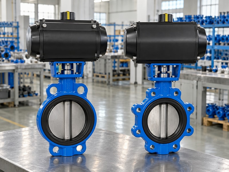
Follow both movement paths
Trace the supply and exhaust routes on the pneumatic schematic. In a spring-return arrangement, trapped chamber pressure can oppose the springs. In a double-acting arrangement, the actuator's final response depends on the pneumatic circuit, remaining pressure, external load, and any holding devices. Avoid promising that every double-acting valve will stay exactly where it stopped.
The assembly needs a defined response for the actual installation, including the influence of process torque on the disc.
- Identify which energy source drives each direction.
- Review the pneumatic circuit with the valve assembly.
| Arrangement | Powered movement | Return movement |
|---|---|---|
| Spring return | Air opposes the spring load | Springs act when the air chamber exhausts |
| Double acting | Air drives one chamber | Air drives the opposite chamber |
2. Which failure response should decide the choice?
Choose spring return butterfly valves when a specified loss of operating energy must move the valve toward an agreed position and the complete assembly can deliver that action. A tank inlet may need closure to stop uncontrolled filling. A cooling line may need an open path under a particular failure sequence. The process designer must assess the actual system.
A label such as fail-safe does not select the right response without identifying the hazard and failure event.
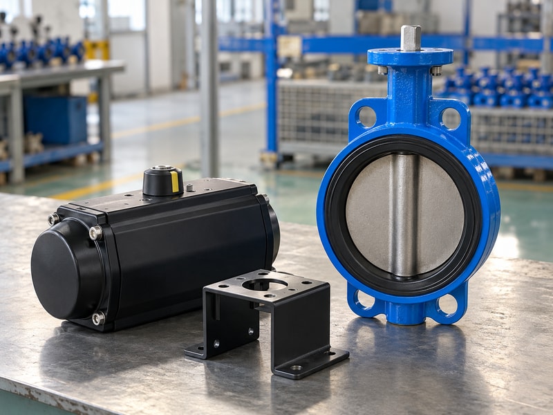
Build a cause-and-effect schedule
Separate loss of electrical power, loss of air pressure, loss of control signal, and utility restoration. An energized solenoid can change state on electrical loss while compressed air remains available. A signal failure can leave the supply intact and produce another response. State whether restart requires an operator reset.
The approved schedule should tell the valve supplier which motions must occur and tell the commissioning team how to test them without creating an uncontrolled process change.
- Record the required endpoint for each event.
- Define reset and automatic restart conditions.
| Event | Required decision |
|---|---|
| Electrical supply lost | Solenoid state and resulting valve action |
| Air pressure lost | Exhaust path and spring capability |
| Control signal lost | Controller response while utilities remain available |
3. How should you compare the available torque?
Compare spring return butterfly valves by checking actuator output against the valve load through both strokes. The air stroke must overcome the valve load while compressing the springs. The return stroke must meet the valve load using available spring output. A double-acting actuator has a separate output curve at the specified air pressure.
Maximum catalogue torque is insufficient for either selection because valve breakaway, running, and seating demands vary across travel and service conditions.
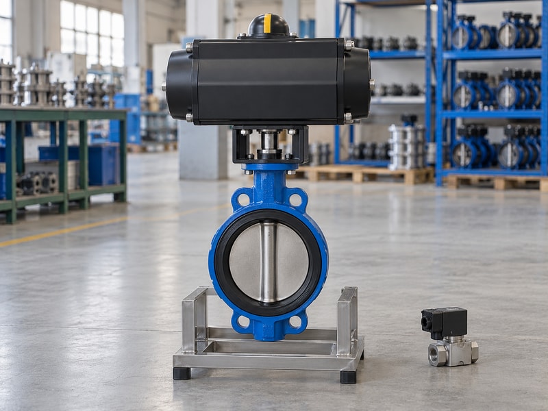
Compare curves at matching conditions
Use the same valve size, seat, closing differential pressure, temperature, and installation assumptions when comparing alternatives. Ask for minimum dynamic supply pressure and the sizing allowance used. Check the shaft, coupling, and bracket limits as well as the available torque reserve. For spring return butterfly valves, a completed sizing sheet should show the controlling stroke and travel region.
Keep that evidence when a supplier proposes a different actuator or seat compound during production.
- Check air and spring output independently.
- Confirm interface limits before increasing actuator size.
| Comparison | Common basis |
|---|---|
| Valve demand | Actual service and maximum closing differential |
| Air output | Pressure available during movement |
| Spring output | Complete return curve and required endpoint |
4. Do spring-return assemblies always consume less air?
Air consumption for spring return butterfly valves depends on the selected actuator size, chamber volume, supply pressure, and cycle pattern. A spring-driven return does not require a second powered air stroke, but the air stroke also compresses the springs. A larger spring-return actuator can change the comparison with a smaller double-acting unit. Compare the supplier's stated air demand for the actual pair of assemblies rather than applying a universal percentage saving to every valve.
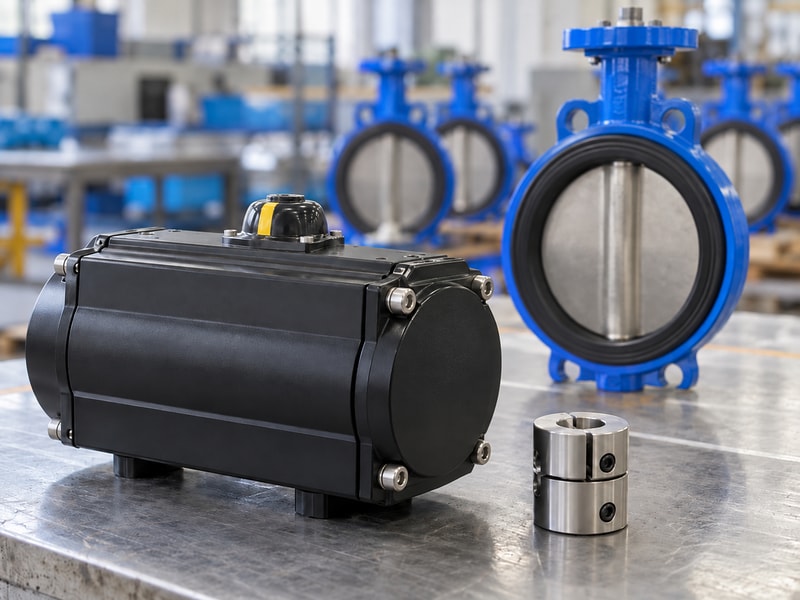
Distinguish consumption from peak flow
Average consumption helps evaluate compressor demand over repeated cycles. Peak flow affects whether the actuator receives enough air during a stroke. A small regulator or restrictive tubing can cause pressure to fall even when the total compressor capacity appears adequate. Ask whether consumption figures refer to free air or compressed chamber volume and retain the stated reference conditions.
Include accessories and leakage assumptions when preparing a site estimate so the figures remain comparable between quotations.
- Use the same pressure and reference conditions.
- Check peak supply and exhaust capacity separately.
| Quantity | Use |
|---|---|
| Air per complete cycle | Estimate demand across the operating schedule |
| Instantaneous flow | Check movement speed and pressure drop |
| Standby leakage | Assess continuing demand between operations |
5. How do size and mounting space affect selection?
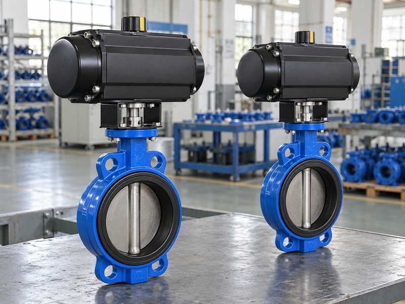
Spring return butterfly valves need enough clearance for the selected actuator, mounting hardware, controls, and service access. Spring packs can increase an actuator's envelope, but the actual difference depends on the designs being compared. Check length, width, height, mass, and removal paths from approved drawings. A package that fits between adjacent pipes may still leave no room to inspect a coupling, remove a solenoid coil, or service a cable entry.
Review the assembled envelope
Compare complete assemblies rather than actuator bodies alone. Include limit-switch boxes, air preparation equipment, tubing bends, manual overrides, and insulation boundaries where applicable. Check mounting strength for the actual operating torque and package mass. The connection details for spring return butterfly valves also need the correct flange fastening arrangement and disc clearance.
An actuator footprint can be compatible while its drive connection, shaft engagement, or bracket stiffness still needs a separate review.
- Keep access for controls and mechanical inspection.
- Verify the complete valve-actuator drawing.
| Space | Check |
|---|---|
| Actuator envelope | Nearby piping, trays, and structures |
| Drive connection | Engagement, alignment, and torque capacity |
| Maintenance path | Safe access without disturbing live equipment |
6. Which costs belong in the comparison?
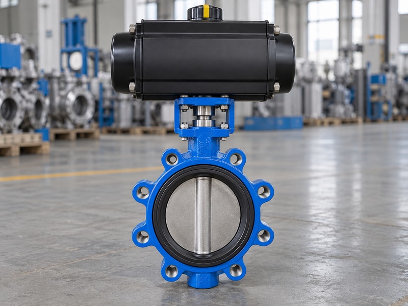
The cost comparison for spring return butterfly valves should include the equipment needed to achieve the same duty and acceptance requirements. Compare the valve, actuator, mounting kit, controls, feedback, air preparation, installation work, and specified testing. A low actuator price can omit components included in another offer. A more expensive actuator may also be unnecessary where the process does not require its return action.
Establish the duty before comparing total installed cost.
Make quotation exclusions visible
Request an itemized scope and an approved list of assumptions. Identify who sizes the actuator, assembles the mounting kit, sets travel limits, checks feedback, and performs the loss-of-utility test. Include access costs where installation space complicates maintenance. Compare spares for the offered valve and actuator configuration rather than generic repair kits.
Lifecycle estimates should use the site's expected cycle count, inspection strategy, and service conditions; an unsupported service-life claim cannot replace those inputs.
- Compare equivalent assembly boundaries.
- List excluded installation and acceptance work.
| Cost item | Scope question |
|---|---|
| Purchased package | Are controls and mounting hardware included? |
| Commissioning | Who performs and records the functional checks? |
| Maintenance | Which configuration-specific spares and access are needed? |
7. What changes when you replace an existing actuator?
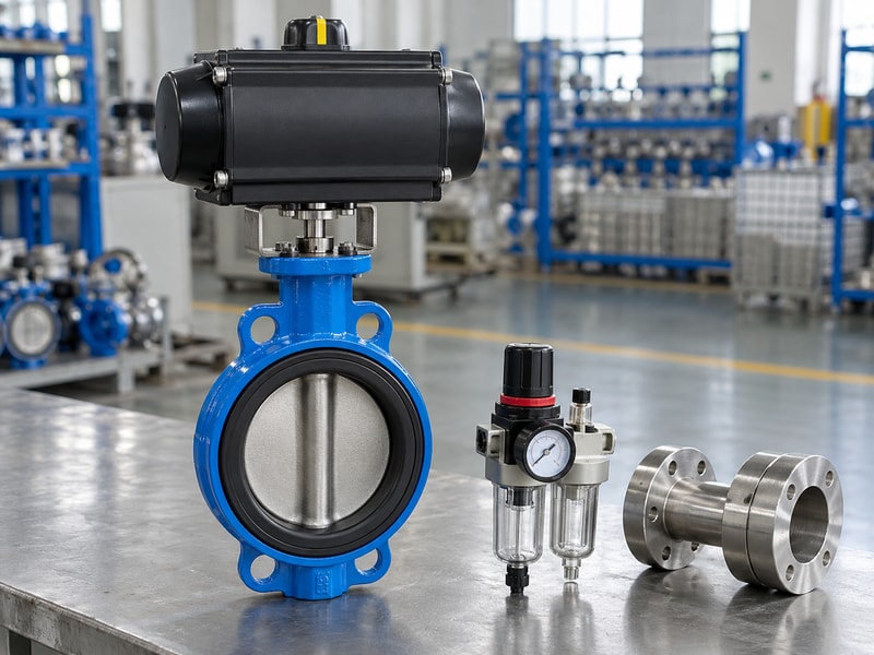
Retrofitting spring return butterfly valves can require changes to both mechanical and control interfaces. Confirm the existing valve's operating torque, shaft geometry, mounting dimensions, seat condition, and permitted travel. Then review the new actuator, pneumatic schematic, solenoid function, feedback, and supply capacity. A mounting flange that accepts the same bolt pattern does not establish compatible torque or failure behavior.
Treat the replacement as an assembly review rather than a hardware swap.
Retain the valve's service boundary
The valve body and seat still limit pressure, temperature, media compatibility, and shutoff performance after the actuator changes. Existing corrosion or seat damage can raise operating torque. A butterfly valve configuration selected for one pressure direction may need another review if the duty changes. Check the return timing against the piping system and revise the operating procedure before commissioning.
Preserve the original records so the differences introduced by the retrofit can be identified and tested.
- Inspect the valve before sizing its replacement drive.
- Update the control sequence and maintenance records.
| Interface | Possible change |
|---|---|
| Mechanical | Bracket, coupling, shaft engagement, and travel stops |
| Pneumatic | Solenoid function, tubing, and exhaust arrangement |
| Electrical | Contact states, signal interpretation, and restart logic |
8. How do you verify the selected failure action?
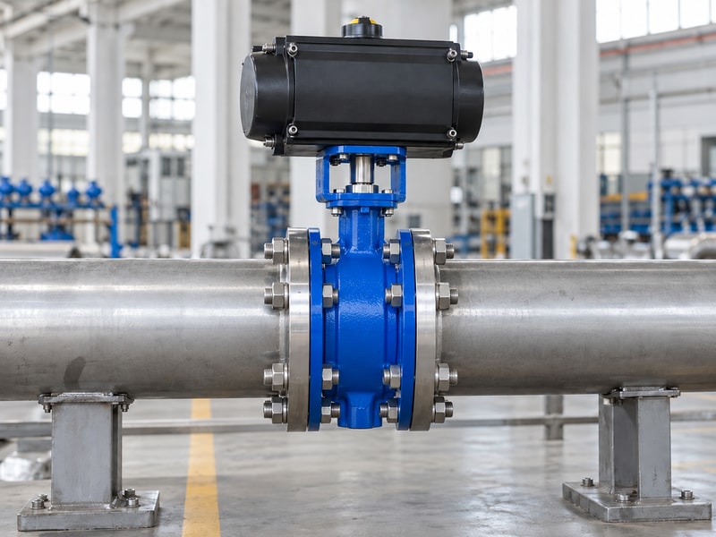
Verify spring return butterfly valves by testing the specified failure events on the complete assembly under the agreed conditions. Record the initial state, supply conditions, control state, travel time, final position, and feedback response. A no-load actuator test provides useful component evidence but does not cover installed valve friction or the required closing differential pressure. Agree on which conditions the factory test covers and which checks must be completed during site commissioning.
Keep functional and leakage evidence distinct
A valve reaching its closed endpoint does not prove that leakage meets the project criterion. Specify the pressure direction, test medium, test pressure, duration, and acceptance basis for shutoff testing. Identify safe isolation and stored-energy controls before any test or maintenance activity. Keep actuator spring housings closed unless the manufacturer's authorized procedure covers their service.
After adjusting stops or replacing components, repeat the checks affected by that change rather than relying on the original certificate alone.
- Test each listed utility or signal failure.
- Record leakage acceptance separately from position indication.
| Test record | Purpose |
|---|---|
| Functional return | Verify movement under specified failure conditions |
| Feedback | Confirm the reported states match actual travel |
| Shutoff leakage | Check the agreed sealing criterion |
9. What should an approval-ready comparison contain?
An approval-ready comparison of spring return butterfly valves should connect the process requirement with the offered equipment and its evidence. Use a single duty sheet for both spring-return and double-acting alternatives. Mark any difference in fail action, return torque, supply demand, travel time, footprint, feedback, and test scope. Record why the chosen alternative meets the duty.
That record gives purchasing and maintenance teams a usable basis for evaluating later substitutions.
Ask for a matched package
Send the supplier the fluid, size, connection drawing, temperature, pressure, closing differential, available utilities, cycling schedule, and required cause-and-effect sequence. Ask for the complete assembly drawing and sizing basis before release. RUITO can review a proposed valve and actuation arrangement against those inputs, with configuration and acceptance requirements confirmed for the order. Identify unresolved items on the quotation so a missing pneumatic accessory or an untested return condition does not first appear during installation.
- Compare one agreed duty across all offers.
- Resolve exclusions and substitutions before dispatch.
| Approval item | Evidence |
|---|---|
| Process response | Approved failure and restart sequence |
| Assembly matching | Drawing, torque comparison, and interface data |
| Acceptance | Agreed factory and site test boundaries |
10. What do buyers ask when comparing actuator options?
Q1. Can I assume a double-acting valve stays in place after air loss?
No. Its response depends on trapped pressure, the pneumatic circuit, process torque, leakage, and any holding devices. Specify and verify the required response for the actual assembly.
Q2. Are spring-return actuators always larger?
No universal comparison applies. Spring packs can increase the envelope, but check drawings for the actual actuator sizes, torque requirements, controls, and mounting hardware.
Q3. What is the best way to compare air demand?
Use the supplier's data for the two selected assemblies at matching reference conditions. Compare air per complete cycle, peak flow during movement, and standby leakage separately.
Q4. Can I keep the existing solenoid after changing actuator type?
Only after checking its function and pneumatic connections. The new arrangement may need a different supply and exhaust path, flow capacity, coil behavior, or manual override arrangement.
Q5. How do I know which actuator arrangement to buy?
Start with the required failure response. Then compare complete-stroke torque, supply conditions, installation space, controls, and acceptance evidence against the same valve duty.
Share the duty sheet and required failure responses when you contact us. RUITO can review the proposed assembly and identify the data still needed for selection.