
A triple offset butterfly valve combines two shaft offsets with an angular offset in its conical sealing geometry. That geometry reduces rubbing between the sealing surfaces through most of the stroke. For a purchase enquiry asking "what is a triple offset butterfly valve", the next checks are the exact seal design, operating limits and required seating torque.
1. What is a triple offset butterfly valve?
A triple offset butterfly valve is a rotary disc valve whose third offset lies in the geometry of the sealing cone. The other two offsets concern the shaft's position relative to the sealing plane and bore centreline. The sealing surfaces are designed to separate during opening and meet as the disc reaches closure. Confirm the actual geometry on the manufacturer's section drawing rather than counting visible body features.
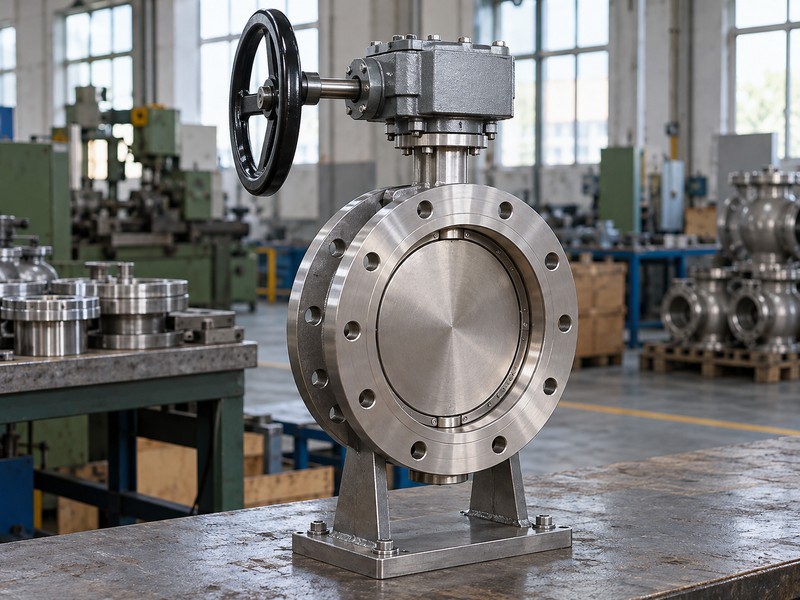
Which three relationships should the drawing show?
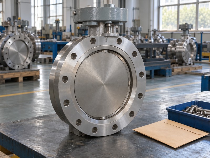
The drawing should locate the shaft, bore axis, sealing plane and conical seat relationship clearly enough to identify the proposed design. External flanges, mounting brackets and actuator position do not count as offsets. A product photograph may conceal most of the geometry behind a closed disc. Request the exact model's section and material list before treating an illustration as proof of a particular sealing construction.
- Locate the two shaft offsets on the section.
- Identify the angular relationship of the sealing cone.
- Match the drawing to the quoted model and seal construction.
| Offset relationship | Design information needed | Avoid inferring it from |
|---|---|---|
| Shaft and sealing plane | Location of shaft behind the sealing plane | An external actuator bracket |
| Shaft and bore centreline | Lateral shaft displacement | Paint or body symmetry |
| Conical sealing geometry | Seat-cone axis and mating surfaces | Flange count or a closed-disc photograph |
2. How does the conical seal close?
The mating conical surfaces approach contact as the disc reaches its designed closed position. The drive then supplies the seating torque needed by the particular seal arrangement. This differs from treating an elastomer sleeve as a continuously compressed bore lining. The seal ring, body seat, retaining parts and travel limits must work together, because contact geometry alone cannot compensate for damaged surfaces or incorrect assembly.
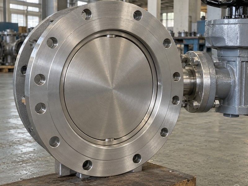
Does reduced rubbing mean the valve needs little torque?
Reduced rubbing through the stroke does not establish a small final seating requirement. Seat load, differential pressure, shaft friction and the actual disc position all affect required torque. Ask for the full operating-torque curve and the accepted seating window. A drive that reaches its own stop early may indicate closed without applying the intended seal load, while excessive output can damage the shaft or sealing assembly.
- Check required torque through the stroke and near closure.
- Verify travel stops against the valve's seating instructions.
- Keep maximum drive output within valve and mounting limits.
| Part of movement | What to review | Possible mismatch |
|---|---|---|
| Opening from the seat | Breakout torque and seal separation | Drive cannot release the disc |
| Running travel | Hydraulic and mechanical torque | Insufficient output at an operating position |
| Final closure | Required seating torque and permitted travel | Early stop or excessive seating load |
3. How does triple offset differ from other butterfly designs?
Triple offset adds a defined conical sealing relationship to an eccentric disc arrangement. A double offset design uses two shaft offsets, while a concentric design centres the shaft and disc within its specified seat system. These differences affect how the seal engages and separates. They do not by themselves establish the pressure rating, temperature range, body connection or test acceptance criterion.
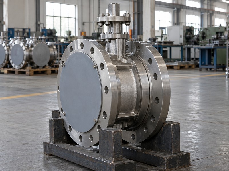
Why should you separate geometry from connection?
A wafer body describes how a valve fits between pipe flanges; it does not define the number of offsets in every manufacturer's product range. Lug and flanged connections are also separate design choices. Compare the complete proposed valve with the existing interface, including length, disc envelope and drive mounting. A change in sealing geometry can require a new torque review even when a nominal size and flange pattern remain the same.
- Name the sealing geometry and body connection separately.
- Review materials and leakage requirements independently.
- Treat a substitution as a complete interface and duty check.
| Classification | What it describes | Still required |
|---|---|---|
| Concentric or offset | Disc, shaft and seat geometry | Materials and operating limits |
| Wafer, lug or flanged | Pipe connection arrangement | Dimensions and load limits |
| Manual or powered | Operating package | Torque, speed and failure response |
4. Which metal-seat and seal-ring details need checking?
Check the exact body seat, disc seal ring, retaining parts and auxiliary seals rather than accepting the phrase metal seated as a complete material specification. Designs may use different metallic or laminated sealing arrangements, and those parts can have different chemical and thermal limits. Packing, gaskets and bearings also affect the finished valve. A metal contact surface does not make every component metallic or suitable for any temperature.
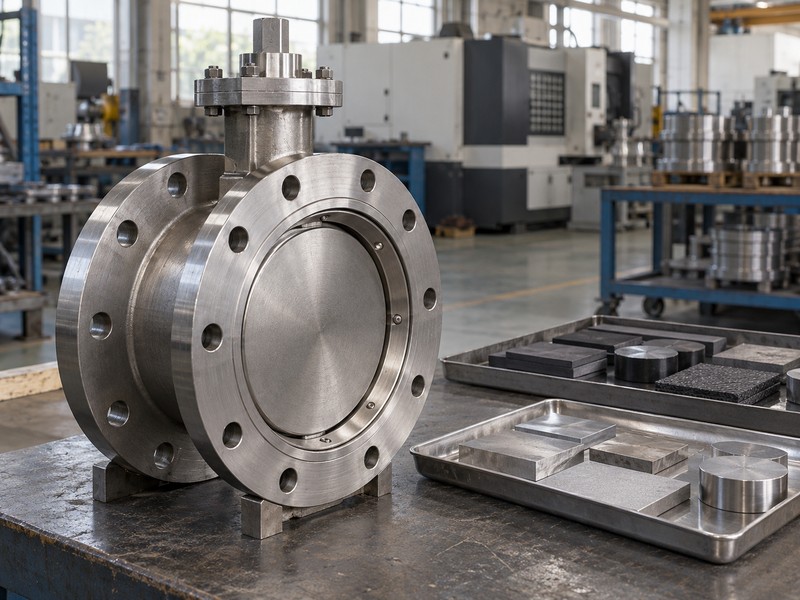
Can a material name establish chemical resistance?
No. Review the complete fluid composition, temperature, pressure and cleaning exposure against every wetted component. A laminated seal can include materials that need a separate compatibility check. A PTFE-lined valve uses a different approach to wetted-surface isolation and should not be treated as an interchangeable metal-seat substitute. Ask the supplier to identify the actual material of each sealing layer and the traceable part specification.
- List the seat, seal ring, retainers, packing and gaskets.
- Identify any nonmetallic layers in a laminated seal.
- Check the whole wetted assembly against the actual fluid.
| Component | Information to request | Why it matters |
|---|---|---|
| Seat and seal ring | Exact grades, layers and construction | Controls sealing and fluid compatibility |
| Packing and gaskets | Material and temperature limits | Controls external containment |
| Retaining parts | Materials and fastening details | Maintains the intended seal geometry |
5. How should pressure, temperature and medium be reviewed?
Review pressure, temperature and medium together for the exact quoted valve. A catalogue family may include several materials and ratings, so its highest published temperature and pressure may belong to different models. The seat, pressure boundary, packing and connection can impose different limits. Use the lowest applicable limit under the same operating case rather than combining unrelated maximum values.
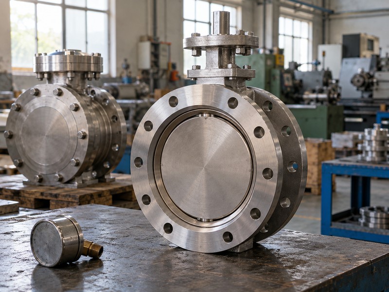
What does the word high performance fail to establish?
It does not establish a universal steam, chemical, gas or cryogenic capability. Give the supplier normal, startup, shutdown and upset cases, including the required closing differential. Ask for a model-specific pressure-temperature relationship and the actual medium review. If the proposed use needs a special material, fire-performance test or low-temperature qualification, confirm that evidence separately instead of deriving it from triple offset geometry or metallic seating.
- Keep pressure and temperature paired in each duty case.
- State fluid composition, cleaning conditions and contaminants.
- List special qualification requirements in the enquiry.
| Duty input | Required form | Selection result |
|---|---|---|
| Pressure and temperature | Simultaneous operating cases | Exact model's permitted envelope |
| Medium | Composition and relevant properties | Complete wetted-material review |
| Special service | Project-specific qualification requirement | Evidence covering the proposed build |
6. Does triple offset guarantee equal shutoff in both directions?
Triple offset geometry does not by itself guarantee equal shutoff differential in both directions. Pressure can load the disc and sealing parts differently depending on direction and design. The model may have a preferred installation direction or separately declared reverse limits. Flow through an open valve in either direction is a different question from closing tightly against a specified reverse pressure.
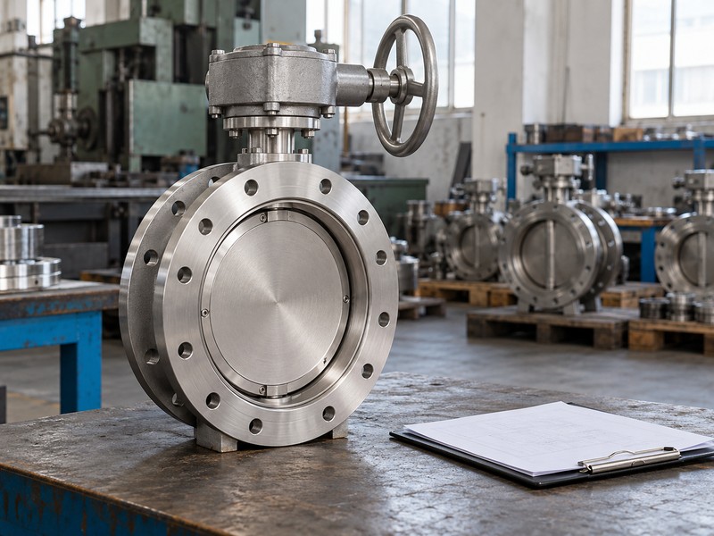
How do you verify the directional claim?
Request the data sheet, section drawing and closure-test records for the stated directions. The evidence should identify pressure, temperature, test medium and acceptance criterion rather than use an unqualified bidirectional label. Record any arrow or direction marking with its defined meaning. A marking could concern preferred pressure, installation or another operating requirement, so compare it with the approved instructions before deciding how the valve should face.
- Give maximum closing differential for each required direction.
- Ask what any body arrow specifically means.
- Match the closure report to direction and acceptance criterion.
| Claim | Question to ask | Useful evidence |
|---|---|---|
| Flow in either direction | Under which open-valve conditions? | Hydraulic and installation data |
| Shutoff in both directions | At which differentials and temperatures? | Declared directional ratings |
| Tight closure | Under which test procedure? | Traceable direction-specific closure results |
7. How do you match the actuator to a torque-seated valve?
Match the actuator's available output to the valve's required torque at each relevant disc position and supply condition. Then check the drive's maximum possible output against allowable valve-shaft and mounting loads. The final seating requirement needs explicit attention in a torque-seated design. A generous catalogue torque figure is insufficient if the drive cannot deliver it where needed or can overload the valve elsewhere.
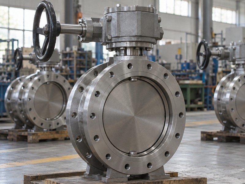
Which settings need an assembled-package test?
Verify travel limits, seating control, torque limits, position indication and the response to each defined loss-of-energy case. A closed feedback signal should agree with the approved mechanical travel and seating arrangement. Confirm coupling dimensions, bracket stiffness and available operating access as part of the same review. Electric and pneumatic packages have different output characteristics, so do not transfer one actuator selection directly to another drive type.
- Compare complete valve and drive torque curves.
- Check minimum supply and maximum output cases.
- Verify travel, seating and feedback on the assembled unit.
| Package item | Required check | Reason |
|---|---|---|
| Drive output | Torque at relevant positions and supply conditions | Confirms movement and seating capability |
| Shaft and mounting | Maximum allowed load | Prevents mechanical overload |
| Stops and feedback | Agreement with approved disc travel | Avoids a false closed indication |
8. What should inspection cover besides a leakage result?
Inspection should cover dimensions, material identity, sealing-surface condition, assembly, operating torque and the agreed pressure tests. A single acceptable leakage result does not establish flange fit, correct packing or repeatable drive settings. The seal ring and body seat also need their approved manufacturing and assembly controls. Keep the records linked to the supplied product ID and drawing revision.
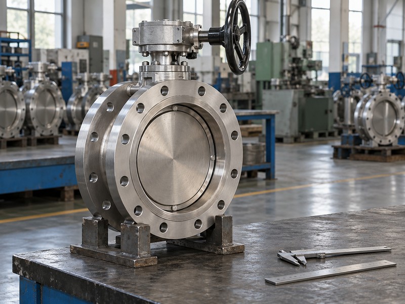
Can a damaged seal be repaired by general polishing?
Use the manufacturer's repair instructions and acceptance limits. Uncontrolled polishing or filing can change the mating geometry or remove a required surface condition, so visual improvement alone cannot establish a successful repair. Compare the flanged interface and disc-clearance details with the installation drawing as well. Any replacement sealing component must match the approved design and pass the required post-repair checks before the valve returns to its duty.
- Check seal identity, retention and visible surface condition.
- Verify interface dimensions and the open-disc envelope.
- Use an approved repair and reinspection procedure.
| Inspection area | Evidence | Limit of the result |
|---|---|---|
| Materials and dimensions | Traceable records against approved documents | Does not establish every operating duty |
| Pressure and leakage | Agreed procedure and acceptance report | Applies to stated test conditions |
| Operating package | Torque, travel and feedback record | Needs the actual approved drive settings |
9. How do you write a reviewable triple offset enquiry?
A reviewable enquiry names the fluid, size, connection, operating cases, closing differentials, leakage requirement and drive functions. Add the required documents and any special qualification or witness points. Ask the supplier to identify the exact proposed construction and its available scope. A general brochure should not be used to fill gaps in a model-specific offer or establish that an unlisted product is available.
How should you compare two technically different offers?
Compare deviations line by line before comparing price. A closure criterion under ISO 5208 or another contract method must state its test conditions; a broad zero-leakage phrase is incomplete. RUITO's stated standard range does not establish triple offset supply or special high-temperature qualification. You can contact us with the complete requirement to confirm actual product availability and the evidence that a specific proposal would need.
- Request a complete proposed material list and section drawing.
- Identify exceptions to the duty and inspection requirements.
- Confirm actual product scope before treating an offer as equivalent.
| Enquiry section | Include | Compare between offers |
|---|---|---|
| Service | Medium and paired pressure-temperature cases | Permitted operating envelope |
| Valve and drive | Geometry, connection, seal and actuation | Exact proposed construction |
| Acceptance | Documents, tests and witness points | Evidence and unresolved deviations |
10. What do buyers ask about triple offset butterfly valves?
Q1. Can I assume triple offset means zero leakage in all service?
No. A leakage claim needs a defined procedure, test medium, pressure, temperature, direction and acceptance criterion. A successful factory test does not promise permanent leak-free operation under every field condition.
Q2. How do I know whether a seal ring is all metal?
Use the exact material list and section drawing. Some seal constructions contain multiple layers or nonmetallic materials. Appearance and the phrase metal seated do not identify every material in the finished sealing assembly.
Q3. Can I size its actuator from nominal diameter alone?
No. Use required torque through the stroke, closing differential, seating load, supply conditions and allowable shaft torque. Nominal diameter leaves those loads and the drive's output characteristic unresolved.
Q4. What is the best direction for installation?
Follow the exact model's approved instructions and directional ratings. Confirm the meaning of any arrow and the required forward or reverse closing case. Do not infer the permitted direction from the offset count.
Q5. Can I assume RUITO supplies a triple offset model?
No. The stated standard product range does not establish that supply scope. Send the complete requirement and ask for an explicit availability confirmation, proposed construction and relevant qualification evidence.