
Choose a "spring return actuator for butterfly valve automation" by checking the existing valve, required failure response, torque, and complete control arrangement. A matching bolt pattern only resolves part of the retrofit. Inspect and define the assembly before ordering so the new operator can move the valve through both strokes under the specified conditions.
1. What is a spring return actuator for butterfly valve automation?
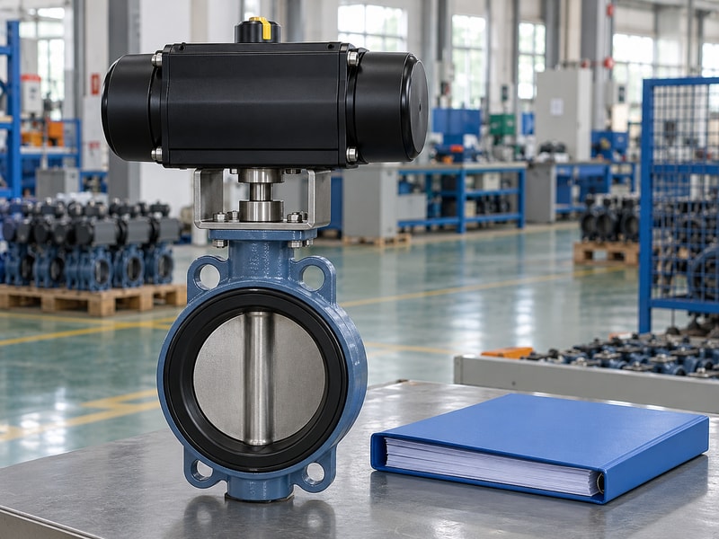
A spring return actuator for butterfly valve automation is an operator that stores spring energy to move the valve shaft toward a specified position when its opposing operating force is removed. A common pneumatic arrangement uses air for one stroke and springs for the return. The retrofit also needs mounting hardware, a compatible drive connection, controls, and adjustment. Define those components together because an actuator delivered on its own cannot establish the behavior of the installed valve.
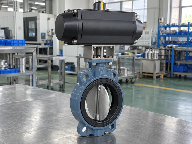
Define the retrofit boundary
Record whether the project replaces a manual operator, changes an existing automatic operator, or adds control features to an assembled valve. Each case can leave different items unresolved. A manual valve may have no existing feedback or utility connections. An automatic package may have controls that suit a different actuator type.
State who inspects the valve, designs the mounting kit, sizes the operator, assembles the package, and completes commissioning before comparing the cost of alternative retrofit offers.
- Identify the existing operator and intended change.
- Assign responsibility for the complete retrofit.
| Starting point | Review boundary |
|---|---|
| Manual valve | Valve condition, drive interface, utilities, and controls |
| Existing automatic valve | Original sizing, control circuit, and failure behavior |
| New assembly | Complete matching, adjustment, and acceptance |
2. Can the existing valve accept an automatic operator?
Before selecting a spring return actuator for butterfly valve automation, confirm that the existing valve can accept the proposed drive and still meet its service duty. Inspect the shaft, mounting surface, seat, body, and operating condition using the manufacturer's procedure. Confirm the actual valve identification and available drawings. A worn seat or distorted installation can raise operating torque, and a damaged shaft connection can make actuator sizing irrelevant until the mechanical defect is corrected.
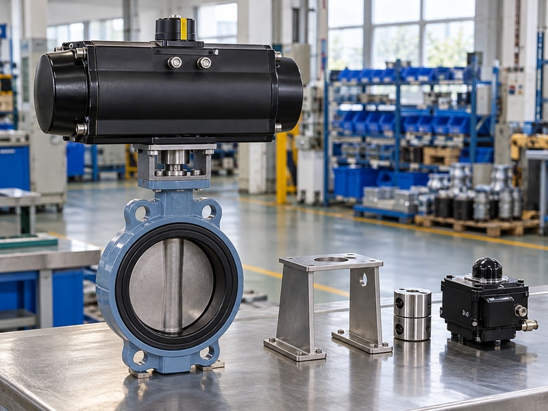
Inspect before measuring or moving the valve
Isolate the equipment and control stored energy before inspecting the drive connection or disc. Do not use an oversized actuator to force a valve through unexplained resistance. Compare the actual installation with the butterfly valve connection requirements, including disc clearance, flange bore, gasket arrangement, and pipe support. If identification or torque data is missing, ask the valve manufacturer how to establish a valid basis.
A measured operating effort under one unloaded condition does not cover every service case.
- Resolve binding, corrosion, and damaged interfaces.
- Confirm the valve's original service and rating boundaries.
| Inspection | Reason |
|---|---|
| Shaft and mounting | Verify a sound drive attachment |
| Seat and disc | Identify wear, damage, or added resistance |
| Installed connection | Check alignment and disc clearance |
3. How do you establish the torque requirement?
A spring return actuator for butterfly valve automation needs a torque comparison based on the actual valve, seat, fluid, temperature, and maximum closing differential pressure. Include breakaway, running, and seating loads where applicable. Compare the air-driven and spring-driven strokes separately and retain the sizing allowance. Ask which operating condition and travel region controls selection.
A catalogue torque associated with nominal valve size can miss the influence of the installed configuration or a change in service.
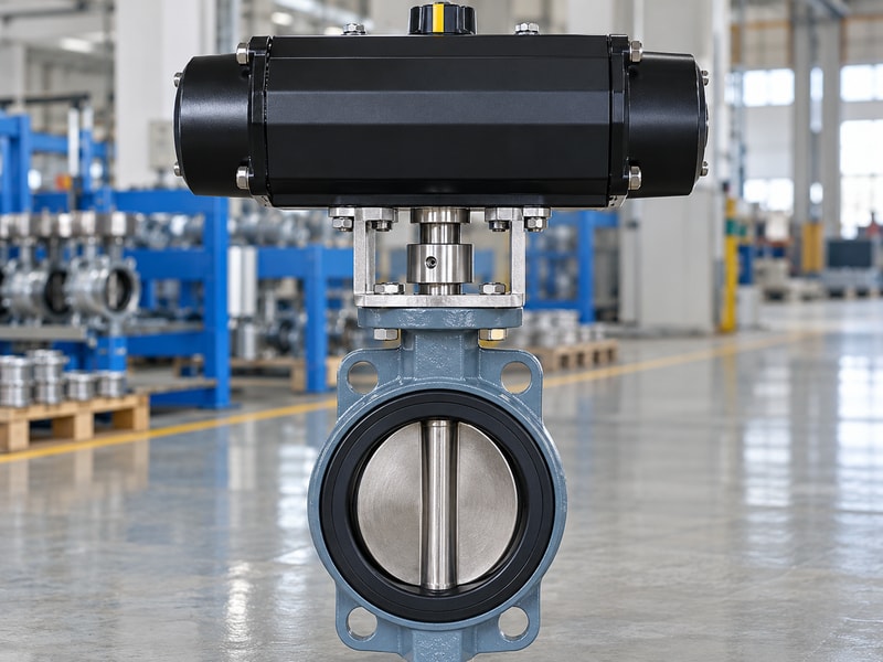
Keep the sizing basis with the retrofit record
Use actuator output at the minimum pressure available during movement. The air stroke has to move the valve while opposing the springs, and the return curve must cover the load toward the required endpoint. Check the permitted torque of the valve shaft, coupling, bracket, and actuator interface. Review the ISO 5211 attachment scope with the offered interface and agreed edition.
The approved assembly still needs its own complete matching calculation and mounting design.
- Use actual service cases and complete-stroke output.
- Check the maximum permissible interface loads.
| Sizing input | Required basis |
|---|---|
| Valve load | Actual configuration and service conditions |
| Actuator output | Air and spring curves through travel |
| Interface limits | Shaft, coupling, bracket, and attachment capacity |
4. Which mounting dimensions must match?
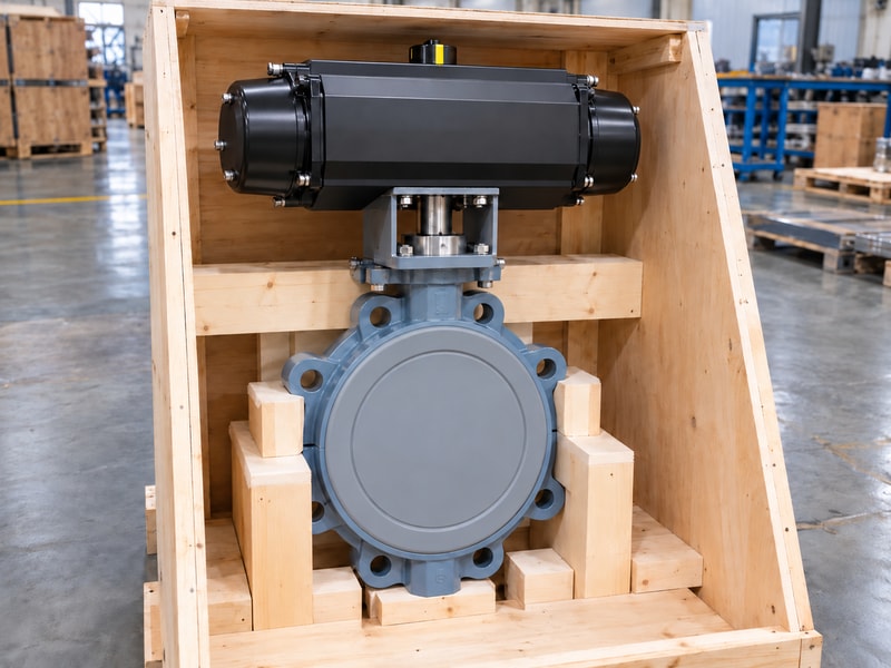
Mounting a spring return actuator for butterfly valve automation requires compatible flange dimensions, shaft geometry, engagement, alignment, and a sufficiently strong mounting arrangement. Check drive shape and orientation as well as the bolt pattern. An adaptor can connect two parts dimensionally while introducing poor engagement or bending. Review the complete mounting-kit drawing so the actuator output axis remains aligned with the valve shaft and the assembly can transmit the required operating torque.
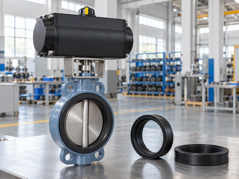
Allow access around the installed package
Confirm that the lug or other butterfly valve interface retains its approved fastening and service arrangement after the retrofit. Include the actuator, limit-switch box, solenoid, tubing, and manual override in the envelope review. Keep space for inspection and component removal without disturbing unrelated live equipment. Check the mounting structure for actuator mass and any applicable installation loads.
Avoid treating a standardized attachment designation as approval of every intermediate bracket or the support-to-valve connection.
- Verify shaft engagement and angular orientation.
- Review the assembled envelope and maintenance access.
| Mounting detail | Check |
|---|---|
| Drive geometry | Shape, dimensions, engagement, and orientation |
| Bracket | Alignment, fasteners, strength, and stiffness |
| Envelope | Controls, removal path, and nearby equipment |
5. What pneumatic changes can the retrofit require?
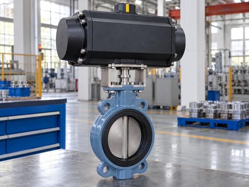
A spring return actuator for butterfly valve automation can require a different supply and exhaust arrangement from the operator it replaces. Confirm the solenoid function, port connections, air quality, pressure during movement, tubing size, and exhaust accessories. The spring stroke needs an effective path for air to leave the opposing chamber. A retained solenoid or an isolation valve can create an unintended pneumatic state if its function was selected for another actuator arrangement.
Follow the exact actuator instructions
Actuator porting and spring-chamber arrangements vary. Use the offered manufacturer's schematic and operating instructions rather than copying a generic connection diagram. Check the effect of manual overrides, exhaust restrictions, and ambient contamination on the specified configuration. Review a flanged butterfly valve assembly with the actual supply boundary, because a complete mechanical package can still arrive without the air preparation or tubing needed at the site.
Agree which accessories the supplier provides and which the installer must complete.
- Confirm porting from the exact operator documentation.
- Check dynamic supply pressure and the return exhaust path.
| Pneumatic item | Retrofit question |
|---|---|
| Solenoid | Does its function produce the required supply and exhaust states? |
| Supply | Is adequate pressure and flow available during travel? |
| Exhaust | Can the spring-driven stroke vent as intended? |
6. How should you revise the control sequence?
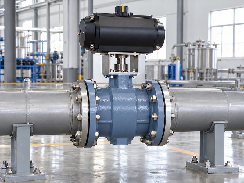
A spring return actuator for butterfly valve automation needs an updated cause-and-effect sequence covering commands, utility loss, signal loss, and restoration. State the required disc endpoint and permitted movement time for each event. Check whether the new operator reverses contact logic or changes the normal solenoid state. A control-system command that worked with the previous package may produce a different physical response after the retrofit, even when the electrical connections appear similar.
Verify indication against actual travel
Adjust local indication and feedback using the assembled valve's movement. Inspect the coupling so actuator travel corresponds to disc travel. Define how open, closed, intermediate, and fault states appear to the control system. A closed contact cannot establish the shutoff leakage criterion.
Where a manual override is fitted, include its engagement and release behavior in the operating procedure. Test the restoration sequence so returning air or electrical power does not create an unreviewed automatic movement.
- Update command, contact, and alarm interpretation.
- Define the required reset after a failure or manual override.
| Control state | Required confirmation |
|---|---|
| Normal command | Correct movement and feedback |
| Utility or signal failure | Agreed endpoint and timing |
| Restoration | Approved reset and restart behavior |
7. What travel-time checks belong in commissioning?
Commission a spring return actuator for butterfly valve automation by checking normal travel and the specified return movement under agreed conditions. Record dynamic supply pressure, starting position, command or failure event, elapsed time, endpoint, and feedback. Compare the results with the approved requirement. The fastest possible stroke may conflict with a liquid-line transient limit, while excessive delay can defeat the intended isolation sequence.
Set timing with the process and piping requirements in view.
Separate bench evidence from installed behavior
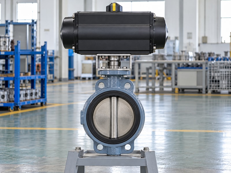
A supplier's assembled test can establish useful movement and control evidence, but the site adds its own utilities, piping, control integration, and process conditions. Identify which checks can be performed safely at the factory and which require site commissioning. If flow-control settings change during installation, record the revised setting and repeat affected tests. Verify the required return from relevant operating positions where the operator permits it.
Keep the resulting baseline for later maintenance comparisons.
- Record conditions with every measured travel time.
- Retest affected behavior after timing adjustments.
| Check | Record |
|---|---|
| Normal movement | Supply, command, travel, and feedback |
| Return movement | Failure event, endpoint, and elapsed time |
| Installed response | Site conditions and any revised settings |
8. Which valve tests remain necessary after automation?
Adding a spring return actuator for butterfly valve automation does not replace the valve's pressure, material, and shutoff requirements. Agree any leakage and pressure tests needed after the work, especially if the seat, shaft seals, or body joint has been disturbed. A successful return stroke shows movement under the test conditions. It does not establish acceptable leakage, a new pressure rating, or compatibility with a different fluid.
Keep those acceptance items separate.
Review changes that affect the original qualification
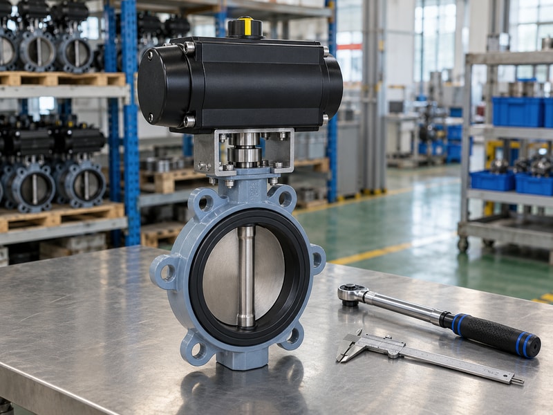
Check whether the retrofit changes the valve's permitted travel, end position, mounting load, service direction, or installed temperature conditions. An operating stop adjusted too far can damage the seat or prevent correct closure. Follow the valve and actuator instructions when setting travel, then verify both position and the specified sealing criterion. Any required safety-function assessment also concerns the complete defined function.
Replacing the operator alone does not establish system-level safety performance or approval.
- Retain the original valve service boundaries.
- Specify the tests affected by assembly or seal work.
| Evidence | What it covers |
|---|---|
| Functional travel | Movement and controls under the test conditions |
| Valve leakage | Selected sealing method and acceptance criterion |
| Service review | Materials, ratings, direction, and operating limits |
9. What should the retrofit handover contain?
A spring return actuator for butterfly valve automation handover should identify the modified assembly and explain its operating, failure, and maintenance conditions. Retain the valve identification, actuator sizing, mounting drawing, pneumatic and wiring diagrams, cause-and-effect schedule, settings, and acceptance records. Note which original documents have been superseded. Maintenance staff need the delivered configuration rather than a collection of unrelated valve and actuator brochures that leave the actual connections unresolved.
Make the next replacement traceable
Record configuration-specific spares and the approval process for substitutions. A later seat change can alter torque; a later solenoid change can alter failure behavior. Keep both changes connected to the assembly review. Ask RUITO to review the existing valve details, actual duty, available utilities, and required failure sequence before confirming a proposed retrofit package.
Include photographs and dimensions where identification is uncertain, while recognizing that photographs alone cannot establish hidden materials, torque requirements, or service ratings.
- Keep the final configuration and settings in one record.
- Identify repeat checks required after future component changes.
| Handover record | Purpose |
|---|---|
| Mechanical and sizing | Identify the matched valve, drive, and mounting kit |
| Controls and sequence | Define actual connections and failure behavior |
| Acceptance and maintenance | Provide a baseline and configuration-specific instructions |
10. What should you ask before automating an existing valve?
Q1. Can I automate any manual butterfly valve?
Only if the valve's condition, drive interface, service rating, and torque basis support the proposed assembly. Inspect and identify the valve before selecting the operator.
Q2. Does the same mounting flange prove compatibility?
No. Check the shaft shape, engagement, alignment, torque limits, mounting-kit design, travel, and complete assembly envelope as well.
Q3. Can I retain the original pneumatic circuit?
Only after reviewing its function against the new actuator. Supply, exhaust, solenoid states, flow capacity, and manual override behavior may need changes.
Q4. How do I know whether a return test is sufficient?
Compare its conditions with the required duty. A no-load or bench test may not cover installed valve resistance, actual utilities, process differential pressure, or site control integration.
Q5. What should trigger a new matching review later?
Changes to the valve seat, actuator, spring configuration, mounting kit, solenoid, operating conditions, or failure sequence can affect the original selection. Review the affected data and repeat relevant tests.
Send the existing valve details and intended control sequence when you contact us. RUITO can review the proposed retrofit scope and the information needed to confirm matching.