
Fix function mistakes by separating manual valve movement, mechanical position sensing and the fire alarm system’s interpretation of a contact change. A tamper switch butterfly valve combines a butterfly valve with a defined position-supervision arrangement. Its supervisory function reports position-related changes; it does not prevent movement, measure waterflow or provide automatic shutoff.
An operator sees a normal valve point on the panel and assumes that water can reach every sprinkler. That assumption can hide a different supply problem, because the point monitors a defined valve-position relationship. Read each function within its scope before relying on the display during a handover or review.
1. What moves in a tamper switch butterfly valve?
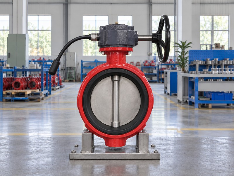
A tamper switch butterfly valve has a mechanical path from its operating input through the shaft to the disc. In a geared manual assembly, handwheel movement passes through a reduction mechanism before turning the shaft. The disc changes its orientation within the valve waterway.
How does disc movement affect the waterway?
Follow the physical parts. An open butterfly disc lies broadly along the flow path, while a closed disc crosses that path and engages its selected seating arrangement. The shaft connection, travel limits and seat condition govern actual movement and closure. A capped signal lead and enclosed operator in an illustration reveal no internal switch construction, sensing relationship or electrical performance.
- Trace handwheel, gearing, shaft and disc separately.
- Read movement limits from selected assembly information.
- Keep visible exterior features within their evidence scope.
Key takeaway: Understand the mechanical movement path before interpreting any position-related electrical signal.
| Check | What you should confirm |
|---|---|
| Input | Handwheel supplies manual operating movement |
| Transmission | Gearing and shaft transmit that movement |
| Waterway | Disc orientation changes the available passage |
2. How does a tamper switch butterfly valve sense position?
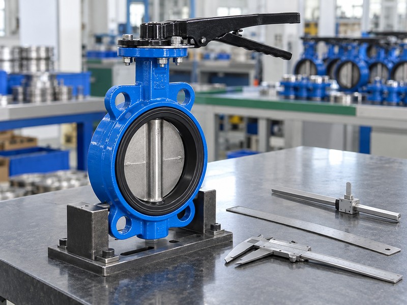
Within a tamper switch butterfly valve, an identified mechanical arrangement operates a position switch as the monitored mechanism moves. A cam or linkage can connect shaft or operator motion with a switch actuator. The exact sensing point and permitted adjustment depend on the selected assembly.
Which relationship does the mechanism monitor?
Locate the sensing connection in its documentation. A cam-operated switch responds when its actuator reaches the mechanism’s defined change point; that electrical change follows the monitored mechanical relationship. It does not directly inspect the entire disc, waterway or pipe network. Matching exterior housings can contain different internal arrangements, so a general photograph cannot identify which moving part operates a particular switch.
- Identify the monitored shaft or operator connection.
- Find the selected cam or linkage description.
- Retain the documented relationship between movement and switching.
Key takeaway: A position switch reports motion at its sensing arrangement, with limits set by that arrangement.
| Check | What you should confirm |
|---|---|
| Mechanical input | Defined shaft or operator movement reaches linkage |
| Switch action | Actuator movement changes the selected contacts |
| Interpretation | Signal describes the documented sensing relationship |
3. Which state is normal for a tamper switch butterfly valve?
Define the intended normal position of a tamper switch butterfly valve from its assigned system duty. A supervised-open supply-control valve normally remains fully open. A location intended to remain closed requires a model and sensing arrangement documented for that different position.
Why can the same valve shape serve different duties?
Read the selected product’s position description. The Victaulic Series 705 document identifies supervised-open service and expressly excludes supervision in the closed position. Other identified product variants provide closed-position supervision through their own configuration. Selecting another contact pair cannot turn an open-only mechanical supervision arrangement into a closed-position model, even when the body and handwheel appear similar.
- Identify the assigned normal position by valve location.
- Match that position with documented sensing capability.
- Retain the distinction when reading contact labels.
Key takeaway: Normal valve position describes a mechanical service condition, independent of contact naming.
| Check | What you should confirm |
|---|---|
| System duty | Defines the intended normal valve position |
| Product design | Provides supervision for its documented position |
| Electrical contacts | Follow that configuration’s selected diagram |
4. How do contacts work in a tamper switch butterfly valve?
Contacts in a tamper switch butterfly valve open or close an electrical path when the mechanism operates the switch. In an SPDT arrangement, a common terminal changes connection between its associated contacts. Labels such as normally open and normally closed must be read using the selected diagram’s reference condition.
Does an open contact mean an open valve?
Keep the electrical and mechanical descriptions separate. An open contact describes a discontinuous contact path, while an open valve describes disc position in the waterway. The manufacturer’s drawing relates those two conditions for the selected assembly. Dry contacts switch the connected circuit without supplying operating power, and their current or voltage rating describes permitted switching duty rather than a required supply or assumed current draw.
- Identify common and associated contacts from selected documentation.
- Read the drawing’s stated valve reference position.
- Separate contact ratings from connected equipment supply needs.
Key takeaway: Interpret continuity through the selected diagram without translating contact names directly into valve positions.
| Check | What you should confirm |
|---|---|
| Valve open | Disc occupies its defined open mechanical position |
| Contact open | Selected electrical path lacks contact continuity |
| Dry contact | Switching action supplies no operating power |
5. What does a tamper switch butterfly valve report?
A tamper switch butterfly valve provides a position-related input that the selected fire alarm system interprets for supervisory duty. Movement from the designated normal position can produce the configured supervisory indication. The switch alone does not decide whether the panel displays supervisory, trouble or fire alarm information.
How do supervisory and fault indications differ?
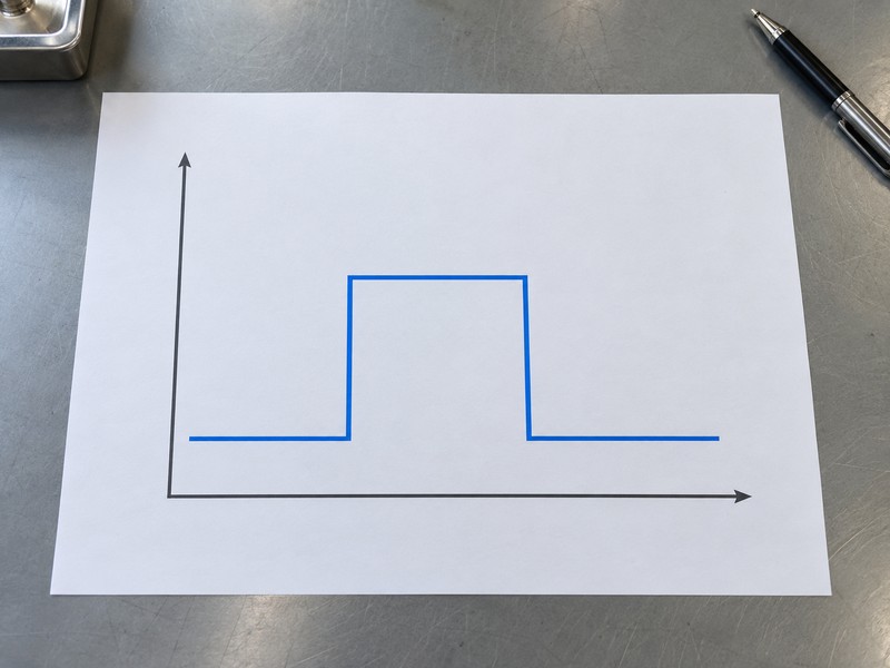
Read the event definition at the panel. A position-related event and a monitored circuit fault describe different conditions, with actual detection and display controlled by the selected input equipment and programming. Waterflow detection also requires its own specified function. The sequence chart shows abstract initial, changed and restored states only, without contact polarity, voltage, valve angle, elapsed time or measured test results.
- Identify the valve point’s assigned supervisory function.
- Separate position events from monitored circuit faults.
- Read restoration through selected equipment and project requirements.
Key takeaway: The panel interprets the input according to its approved configuration and defined event functions.
| Check | What you should confirm |
|---|---|
| Supervisory | Assigned input reports a position-related condition |
| Trouble | Selected equipment detects a defined circuit fault |
| Waterflow | Separate detection reports its specified flow condition |
6. What connects a tamper switch butterfly valve to a panel?
A tamper switch butterfly valve connects through the compatible monitored input specified for the fire alarm system. In an addressable arrangement, a suitable input module can translate contact conditions into messages for the panel. The module’s communication connection and monitored contact input perform different jobs.
Where do the valve’s dry contacts belong?
Follow the selected module’s connection diagram. In the Potter PAD100-MIM instructions, the module joins a compatible signaling line circuit, or SLC, while external contacts use its separate monitored input circuit. Ordinary valve dry contacts must not connect directly across the SLC. End-of-line components, circuit topology, input limits and programming follow the selected equipment rather than a universal tamper-switch convention.
- Separate module communication from its monitored contact input.
- Use the designated supervisory output for its permitted duty.
- Read component values from the selected input diagram.
Key takeaway: The addressable module and the valve contact circuit remain distinct parts of the signal path.
| Check | What you should confirm |
|---|---|
| Panel SLC | Carries compatible module communication and associated functions |
| Monitored input | Receives valve contacts through specified circuit arrangement |
| Auxiliary contact | Retains its separately documented permitted use |
7. What can a tamper switch butterfly valve indicate?
Indication from a tamper switch butterfly valve describes the position relationship monitored by its mechanism and connected circuit. A pointer adds a local visual indication according to its mechanical indexing. Neither indication directly measures available water supply, actual flow, seat leakage or conditions elsewhere in the system.
Why does a normal indication have limits?
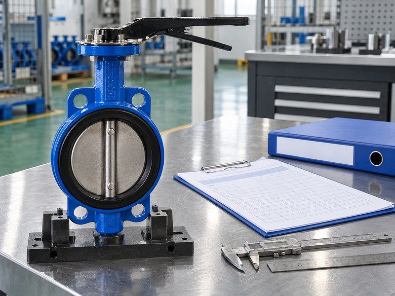
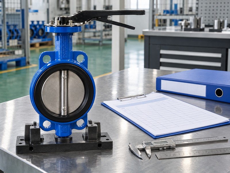
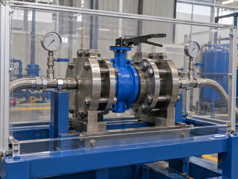
Check what each observation establishes. A pointer can agree with its operator while a damaged or loose connection elsewhere in the drive path needs separate investigation. A normal supervisory point cannot certify an unobstructed waterway or a tight closed seat. The hydraulic fixture illustration concerns a different type of evidence; its appearance supplies no pressure result and proves no electrical supervisory operation.
- Read pointer position within its indexed mechanical relationship.
- Keep waterflow and supply evidence separate from supervision.
- Use appropriate checks for linkage condition and sealing.
Key takeaway: A normal position indication supports its defined function without proving every valve or system condition.
| Check | What you should confirm |
|---|---|
| Pointer | Shows position through its indexed connection |
| Supervisory point | Reports the configured monitored input condition |
| Hydraulic evidence | Addresses its stated flow, pressure or leakage scope |
8. What switch types suit a tamper switch butterfly valve?
A tamper switch butterfly valve can have internal switches within its operator or an identified external sensing arrangement. Both rely on a defined mechanical relationship between valve movement and switch action. Their function depends on the complete documented configuration rather than the location of the switch housing alone.
What changes between integral and external sensing?
Identify how movement reaches the switch. An integral arrangement places its sensing components within the selected operator, while an external arrangement uses the manufacturer’s specified linkage and mounting parts. Some product families limit external accessories to particular valve versions. Adding an arbitrary switch cannot establish correct sensing or fire approval; actual valve, operator and accessory documentation must cover the proposed arrangement.
- Locate the switch and its mechanical operating connection.
- Use identified mounting and linkage arrangements.
- Check actual configuration coverage for the intended service.
Key takeaway: Switch location describes construction; documented mechanical compatibility establishes the intended sensing relationship.
| Check | What you should confirm |
|---|---|
| Integral | Selected operator contains the documented sensing arrangement |
| External | Identified mounting transmits movement to the switch |
| Coverage | Function and approval follow the exact configuration |
9. How should a tamper switch butterfly valve operate?
Correct operation of a tamper switch butterfly valve means its mechanical position, switch behavior and installed panel indication agree with the accepted configuration. Define the intended normal state and required changed-state indication before evaluating performance. Restoration must also match the selected equipment and project procedure.
What does a functional check need to establish?
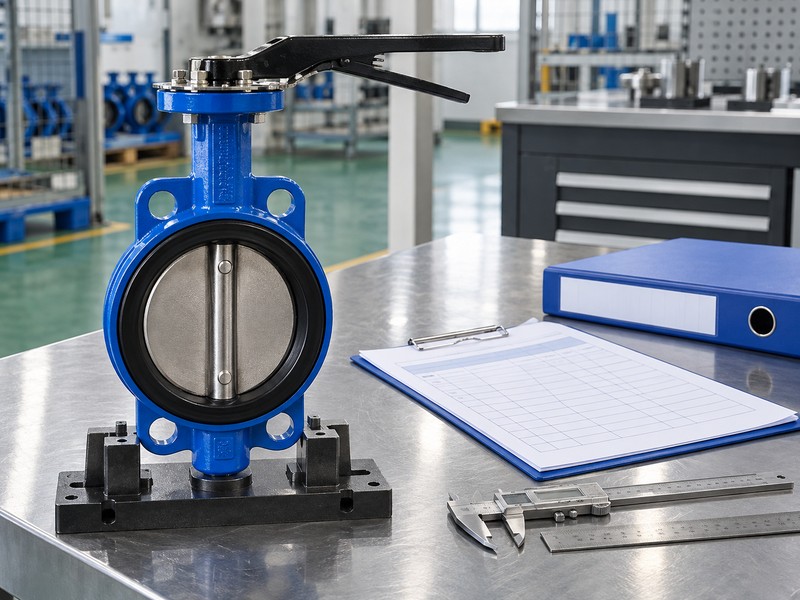
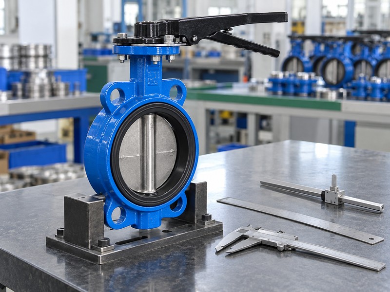
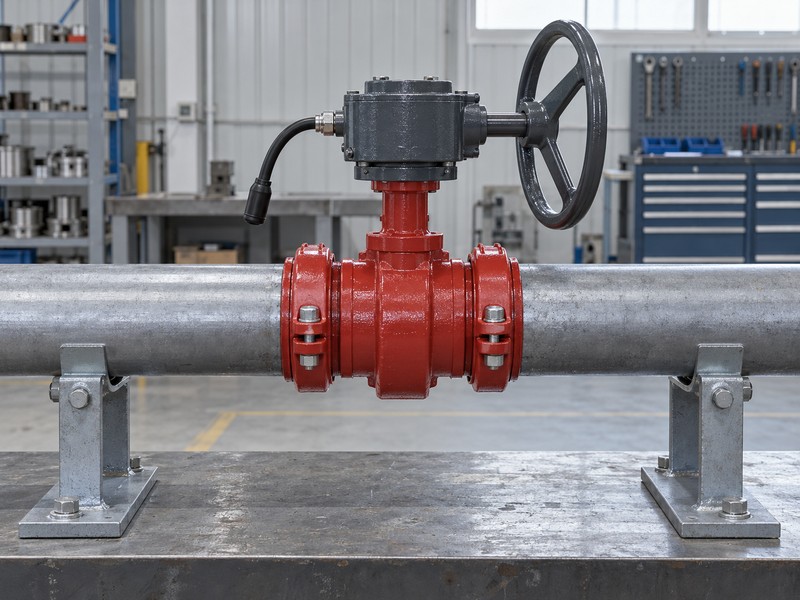
Keep the verification scope explicit. The authorized project procedure should correlate actual permitted valve movement with the designated input event and subsequent restoration, using the selected manufacturer’s acceptance criteria. Physical movement, adjustment and circuit testing require project authorization and the applicable instructions, including any required impairment arrangements. The static installation illustration depicts external layout only and supplies no commissioned electrical or hydraulic result.
- Correlate actual position with the identified supervisory point.
- Apply selected acceptance criteria for change and restoration.
- Record separate mechanical, circuit and panel observations.
Key takeaway: Judge operation against documented relationships and recorded observations rather than a generic trip threshold.
| Check | What you should confirm |
|---|---|
| Normal | Accepted valve position matches its intended indication |
| Changed | Authorized check produces the required supervisory event |
| Restored | Accepted valve and input states return as specified |
10. What keeps a tamper switch butterfly valve dependable?
A tamper switch butterfly valve depends on preserved mechanical connections, suitable environmental protection and a functioning monitored input. Supervision helps personnel identify a specified change, but it does not stop someone turning the handwheel. Physical access control and any required locking arrangement need their own approved provisions.
Which conditions deserve ongoing attention?
Follow the selected maintenance information. Protect operator enclosures, cable entries and moving connections within their environmental limits, and investigate damage or abnormal indications through the responsible team. Inspection and testing frequency comes from the applicable adopted requirements, product instructions and project arrangements. RUITO can review supplied application and assembly information; confirm actual tamper-switch availability and fire-service approval coverage for any proposed supply configuration.
- Retain documented operating and maintenance information.
- Protect components during storage, handling and installed service.
- Assign abnormal indications to the responsible response team.
Key takeaway: Maintain the mechanical assembly and its monitored interface as connected functions with separate checks.
| Check | What you should confirm |
|---|---|
| Condition | Mechanical and enclosure integrity remain within requirements |
| Monitoring | Assigned input and response arrangements stay functional |
| Maintenance | Selected instructions and project requirements govern checks |
Send RUITO the valve identification, intended normal position and available assembly documents if the sensing arrangement remains unclear. We can review the application information and identify which product or interface details still need confirmation. Contact us with those records for an application-specific review.
FAQ
Q1: Does a tamper switch lock the valve open?
No. Position supervision reports a defined change. Access control and any required locking arrangement need separate approved provisions.
Q2: Does a normally open contact mean the valve is open?
No. Contact terminology and valve position describe different conditions. Read their relationship from the selected assembly diagram.
Q3: Can ordinary valve contacts connect directly to an addressable SLC?
No. Connect contacts only through the compatible monitored input arrangement specified for the selected panel and module.
Q4: Does normal supervision prove water is available?
No. The point reports its configured position-related condition. Available supply, waterflow and an unobstructed waterway require their own evidence.
Q5: Can the same trip angle apply to every valve?
No. Use the selected manufacturer’s criteria and authorized project procedure; different mechanisms and supervision arrangements have their own requirements.