
You can avoid costly three inch butterfly valve mistakes by confirming the complete valve, flange bore, disc clearance, and operating conditions before installation. A Viton seat 3 inch butterfly valve description leaves its construction and actual dimensions unresolved. During a shutdown, discovering that the disc strikes a nearby liner can delay the whole job. An approved drawing, compound specification, and installation procedure let you settle those questions before the valve reaches site.
1. What defines a Viton seat 3 inch butterfly valve?
It defines a nominal valve size and a requested sealing material, while the body, disc, connection, and operating limits remain separate choices. Confirm whether the requirement covers a complete new valve or a replacement seat for an existing valve. Those purchases need different dimensions and acceptance checks. A complete valve must match the pipe installation and duty; a loose seat must also match the original valve series and internal geometry.
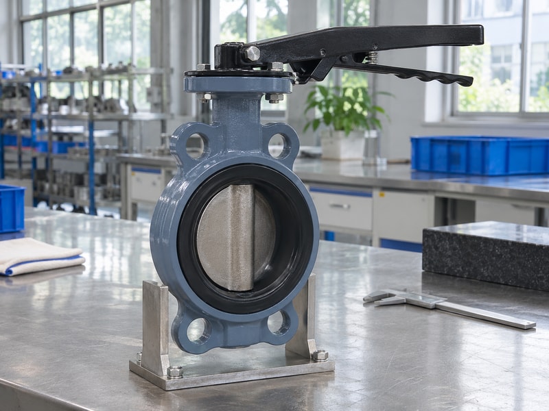
Describe the assembly you intend to buy
Viton is a trademark, and an FKM material declaration does not by itself establish use of the requested branded material. Record the accepted compound description and obtain supplier confirmation. Also identify the wetted disc and stem details, since a suitable seat cannot compensate for another incompatible component.
- State complete valve or replacement seat in the order line.
- Give manufacturer, series, nominal size, and drawing revision.
- Identify the seat compound, disc material, and connection style.
- Define manual operation or the complete actuator package.
| Purchase description | Additional information needed |
|---|---|
| Complete three inch valve | Connection, dimensions, materials, duty |
| Three inch spare seat | Original series and seat geometry |
| Actuated assembly | Torque, mounting, supply, fail action |
A clear order line prevents a nominally correct product from arriving with the wrong interface or an unapproved seal formulation.
2. How do NPS 3 and DN80 relate to the actual bore?
NPS 3 and DN80 are nominal size designations, so neither guarantees an actual 76.2 mm clear bore. Pipe schedule, flange construction, liners, seat projection, and disc shape affect the available opening. The exact conversion of three inches to 76.2 mm describes a length, not the geometry of a nominal three inch piping assembly. Measure the relevant parts and compare them with the selected valve drawing.
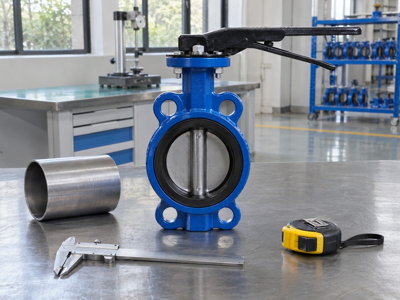
Compare the dimensions that touch the disc
Use actual internal diameters at both flange faces and through nearby fittings. A reducer or lined flange can narrow the opening where the disc projects outside the valve body. An upstream measurement alone may miss an obstruction on the opposite side, particularly when the disc has an asymmetric opening envelope.
- Record pipe material, outside diameter, and wall schedule.
- Measure flange and liner bores at the valve interface.
- Obtain the manufacturer’s minimum mating-bore requirement.
- Check the opening envelope on both sides of the valve.
| Size information | What it tells you |
|---|---|
| NPS 3 or DN80 | Nominal piping size |
| Actual flange bore | Available local clearance |
| Disc envelope drawing | Space needed throughout travel |
Keep the measured bore and approved drawing in the installation pack so the next replacement can be checked against the same physical interface.
3. Which wafer or lug connection fits the line?
The correct connection matches the flange standard, face-to-face space, bolt arrangement, and required maintenance condition. A wafer valve generally sits between mating flanges using the specified through-bolt arrangement. A lug construction uses body lugs with a defined fastener arrangement, but their presence does not establish an unrestricted end-of-line rating. State any requirement to remove downstream pipe while retaining upstream pressure before the supplier selects the construction.
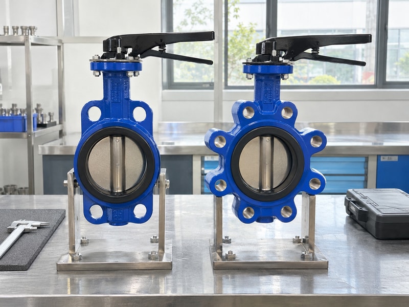
Check bolting and maintenance together
RUITO’s wafer butterfly valve and lug butterfly valve pages describe distinct connection arrangements. Use their construction details to frame an enquiry, then obtain the exact drawing for the proposed seat and service. A water-service lug rating does not automatically cover an FKM chemical-service assembly.
- Identify flange drilling and facing on both sides.
- Confirm face-to-face length and available removal space.
- Specify bolt diameter, length, grade, and thread engagement.
- Obtain written limits for any single-sided pressure condition.
| Site requirement | Detail to approve |
|---|---|
| Existing flange spacing | Exact valve face-to-face dimension |
| Lug attachment | Fastener and engagement drawing |
| Downstream removal | Dedicated terminal-service rating |
Treat connection changes as engineering changes, even when both candidate valves carry the same nominal size and pressure designation.
4. How do you verify disc clearance before installation?
Verify disc clearance by comparing the full opening envelope with both mating bores and then checking free travel under the manufacturer’s installation procedure. The disc can extend beyond the valve body as it rotates. A flange, weld bead, gasket, liner, or nearby fitting may enter that space even when the closed valve fits. Do this review before final tightening and before attaching equipment that conceals resistance during rotation.
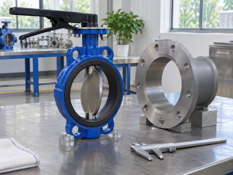
Investigate interference before applying force
Asahi/America’s Type-57P user guide specifies a minimum piping internal diameter by size and calls for checking full-open interference before final bolting. That is an example of product-specific installation evidence, not a dimension table for every three inch valve. Obtain equivalent information for the exact model you are installing.
- Overlay the disc envelope on the flange section.
- Include gasket edges, liners, and adjacent reducers.
- Follow the instructed disc position during insertion.
- Stop if travel becomes tight or contact appears.
| Observation | Action before commissioning |
|---|---|
| Free full travel | Record clearance verification |
| Contact near full opening | Check both adjacent bores |
| Torque rises after bolting | Inspect alignment and seat compression |
Do not grind the disc or modify a liner to obtain clearance without a reviewed repair or interface change.
5. What pressure and fluid conditions need approval?
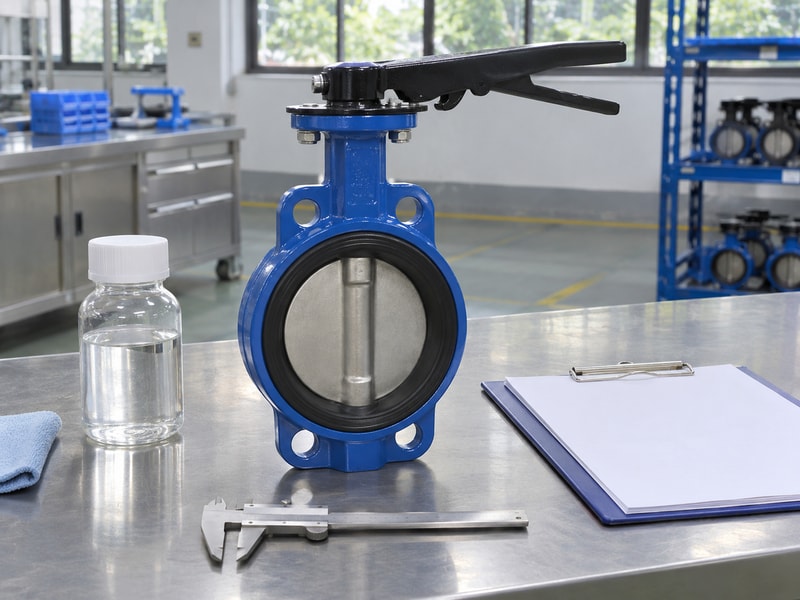
The complete valve needs approval for the actual medium, simultaneous pressure and temperature, maximum closed-disc differential, and all planned cleaning conditions. A seat chemistry chart covers only part of that review. FKM compounds differ, and body, disc, shaft seals, and coatings may have their own limits. Specify the operating direction and any reverse-pressure case rather than assuming the same shutoff performance in both directions.
Separate line pressure from shutoff differential
A valve can experience modest running differential while facing a much larger differential after closure. Pump shutoff, trapped liquid, and startup arrangements can alter that condition. Include those states in the enquiry and ask the supplier to identify the limiting component or rating when a proposed case cannot be approved.
- Give chemical composition, concentration, additives, and solids.
- State normal and maximum pressure with their temperatures.
- Include minimum downstream pressure and vacuum if relevant.
- List cleaning fluid, peak temperature, and exposure time.
| Operating state | Confirmation required |
|---|---|
| Normal flow | Materials and working pressure |
| Closed against pump | Shutoff differential and torque |
| Cleaning cycle | Compound and assembly temperature limits |
Where a lined design needs review, the PTFE lined butterfly valve page provides another construction to discuss, with its own material and service boundaries.
6. How do you check hand lever or actuator access?
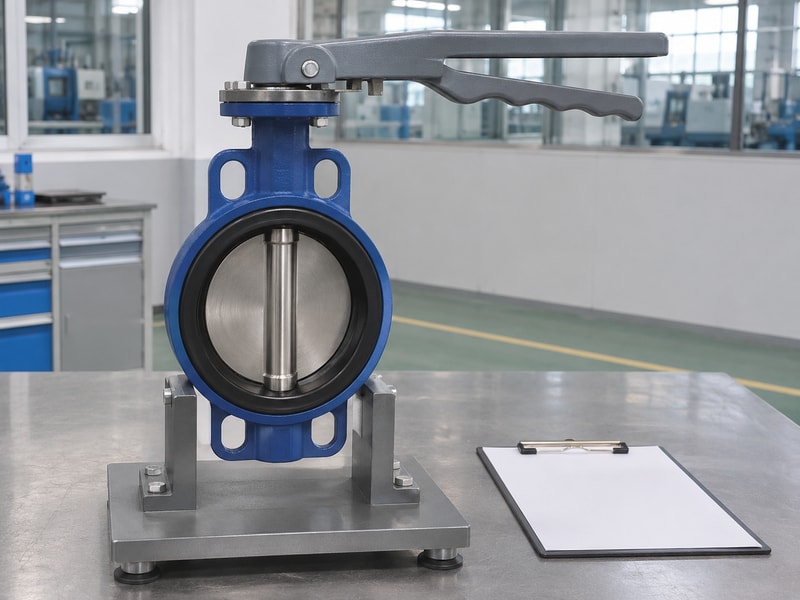
Check access against the complete operating and maintenance envelope, including lever swing, actuator height, cable entry, and removal space. A body that fits between flanges may leave no room to operate its handle or remove a coupling. Confirm the orientation on a layout drawing before purchase. For powered valves, also match torque and travel stops to the exact valve rather than selecting an actuator from nominal size alone.
Review operating loads and service access
Request breakaway, running, and seating torque for the approved differential and temperature conditions. Pneumatic output must be checked at the lowest available supply pressure, including spring-return travel where fitted. Electrical actuation needs the stated supply, duty rating, travel time, and feedback arrangement, with access for the required manual override.
- Confirm handle travel without contact with adjacent equipment.
- Check bracket and coupling dimensions and allowable stem torque.
- Provide access to limit switches and terminal compartments.
- Define fail position and manual isolation arrangements.
| Operation type | Check before installation |
|---|---|
| Lever | Full swing and operator access |
| Gearbox | Handwheel and indicator visibility |
| Actuator | Torque, supply, feedback, and removal envelope |
Ask for a revised layout when accessories change. A replacement actuator can move the terminal box into a wall even if its mounting holes still match.
7. What installation sequence protects the seat?
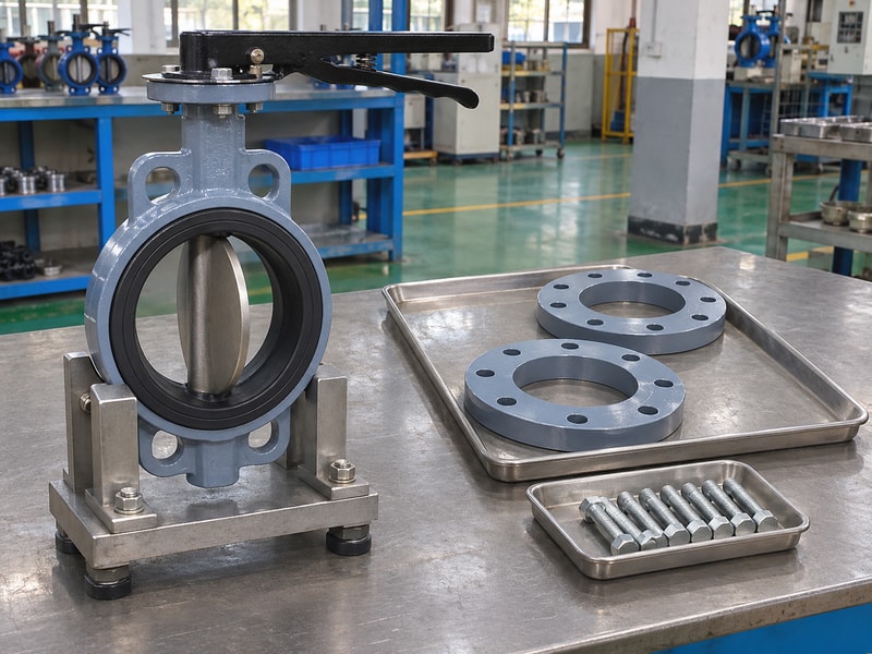
The seat is protected by isolating the line, cleaning and aligning the flanges, using the specified disc position, and tightening under the exact product procedure. Keep the valve away from welding heat and abrasive debris. Flange bolts must not pull misaligned piping into position through the body. Seat designs differ in how they seal against flange faces, so confirm whether separate gaskets are required before assembling the stack.
Use model-specific bolt and travel instructions
Follow the approved tightening sequence, stages, and torque values using appropriate tools. No single bolt torque applies to every NPS 3 body, flange material, and seat arrangement. Inspect free movement at the stages required by the manual, then recheck the final assembly without forcing the handle past its stops.
- Verify isolation, drainage, and the applicable site work procedure.
- Inspect seat lips and disc edges before insertion.
- Center the valve and check the specified gasket arrangement.
- Record final bolting and free-travel checks.
| Installation stage | Seat protection measure |
|---|---|
| Preparation | Remove debris and inspect sealing faces |
| Insertion | Use the instructed disc position |
| Tightening | Follow approved sequence and torque |
If the valve binds after tightening, check fit and compression before changing the actuator stops or applying greater operating force.
8. Which commissioning checks should you record?
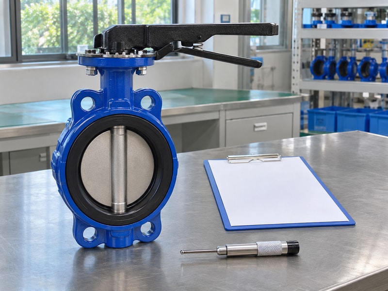
Record the installed identity, free travel, external leakage, specified shutoff performance, and control feedback under an approved commissioning procedure. Factory testing and site commissioning answer different questions: one checks the manufactured valve under stated conditions, while the other checks the installed assembly. Establish acceptable leakage criteria and test conditions before filling the line. A position indicator alone cannot prove the disc has reached its intended position.
Compare commands with actual movement
For an actuated valve, check the open and closed commands, local indication, feedback, and fail action where the procedure permits it. Fill and pressurize at the controlled rate specified for the system. Investigate abnormal torque, noise, or leakage before releasing the valve for normal operation rather than accepting them as initial bedding-in.
- Verify tag, material record, and final drawing revision.
- Confirm full travel and correct stop adjustment.
- Inspect flange joints and shaft seals for external leakage.
- Record pressures, temperature, medium, duration, and result.
| Test record | Information to retain |
|---|---|
| Functional check | Command, observed travel, feedback |
| Leakage check | Conditions and acceptance criterion |
| Installation record | Interface, bolting, and valve identity |
Link defects and corrective actions to the valve tag so maintenance personnel can see what changed before handover.
9. What should a repeat purchase specify?
A repeat purchase should specify the approved configuration and drawing revision, including any changes made during installation or commissioning. Reordering by the words three inch and Viton can lose the details that made the previous assembly work. Include component materials, face-to-face length, flange standard, disc envelope, and actuation package. Require written notification before a supplier changes the seat compound, disc geometry, or mounting arrangement.
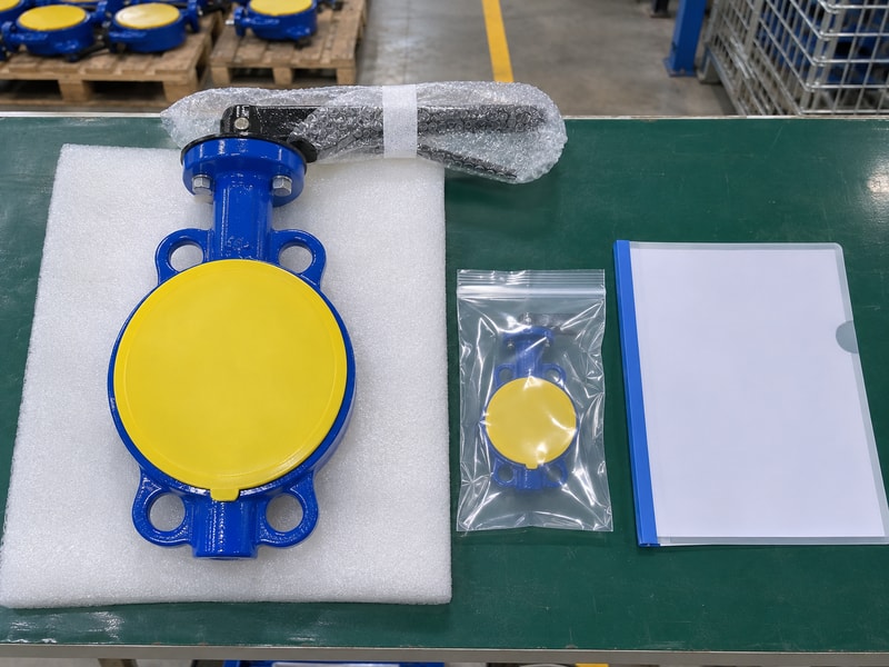
Preserve the installed technical baseline
Keep the final material list and inspection requirements with the purchase record. RUITO’s documented butterfly range provides established metal-body and lined constructions, while a requested FKM configuration still needs product-specific confirmation. An earlier water-service order or a visually similar sample does not establish approval for a new chemical or temperature condition.
- Quote the previous order and approved product identification.
- Attach the final drawing and installation amendments.
- State whether the operating medium or duty has changed.
- Request the agreed documents and replacement parts list.
| Repeat-order item | Reason to retain it |
|---|---|
| Approved compound | Controls seal substitution |
| Disc and interface drawing | Preserves clearance and fit |
| Actuator package revision | Preserves torque and site access |
If a product has changed, compare the proposed replacement with the installed baseline before accepting the revised quotation.
10. What do installers ask about three inch valves?
Q1: Can I assume DN80 means a 76.2 mm bore?
No. DN80 and NPS 3 are nominal designations. Measure the pipe and flange bores and compare them with the valve’s full disc-opening envelope.
Q2: What’s the best bolt torque for a three inch valve?
Use the exact installation manual. Body construction, flange materials, fasteners, and seat arrangement affect the approved torque and tightening sequence.
Q3: Can I remove downstream piping from any lug valve?
No. Confirm the precise terminal-service rating, pressure direction, size, temperature, and permitted fastener arrangement before planning that maintenance condition.
Q4: How do I know if the seat was damaged during fitting?
Check travel, operating torque, and leakage under the approved procedure. Binding or leakage requires inspection; increasing actuator force can worsen an installation problem.
Q5: What should I send with a replacement enquiry?
Send the valve identity, flange dimensions, actual bores, medium, operating cases, and available space. Include the current drawing when you contact us for a configuration review.