
You can avoid butterfly flow control mistakes by sizing the valve across real operating cases and checking its throttling capability separately from seat compatibility. A Viton seat butterfly valve flow control enquiry needs more than pipe size and a maximum flow. An oversized valve may hunt near closure even though it passes the peak flow easily. Give the supplier minimum, normal, and maximum conditions, then review hydraulics, seat duty, and actuator response together.
1. Can a Viton seat butterfly valve control flow?
A suitable butterfly valve can control flow when its complete design is approved for continuous throttling under the proposed conditions. An FKM seat helps meet a chemical sealing requirement; it does not establish control range, cavitation resistance, or acceptable partial-opening duty. Ask the manufacturer to identify the permitted operating region and restrictions for the exact valve. A product approved for isolation may need a different design for frequent or continuous modulation.
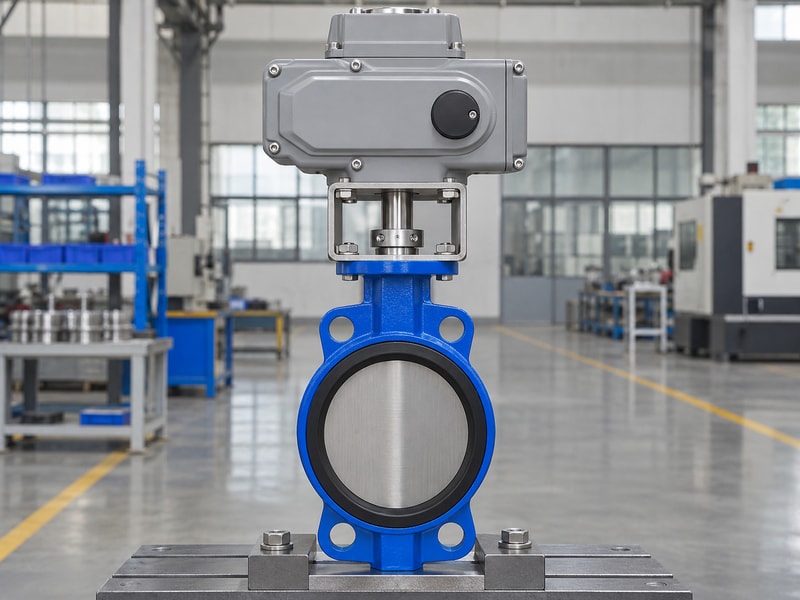
Separate three approval questions
Confirm that the liquid is compatible with every wetted material, that the valve can withstand the hydraulic duty, and that the assembled actuator can position it accurately. Passing one review does not close the others. Tight shutoff requirements also need their own acceptance criterion and operating differential.
- Confirm continuous throttling approval for the selected construction.
- Obtain flow coefficient data against disc position.
- Check allowable differential, velocity, and operating angle limits.
- Define the required shutoff and control performance separately.
| Review | Evidence to request |
|---|---|
| Chemical sealing | Exact compound and wetted material assessment |
| Hydraulic service | Sizing calculation and operating limits |
| Positioning | Actuator and positioner response data |
Keep the selection open until all three reviews address the same valve size, trim, and process cases.
2. What operating cases are needed for sizing?
Sizing needs minimum, normal, and maximum flow cases with the actual upstream and downstream conditions for each case. Those conditions often change together as pumps, parallel branches, or tank levels change. A single pressure drop assumed for every flow can produce a misleading result. Include startup, cleaning, pump shutoff, and other distinct operating states where they affect valve loading or required control.
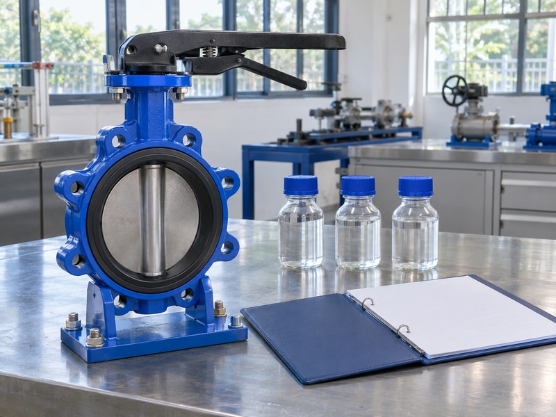
Give each case a complete set of inputs
For liquid duty, provide flow, density or specific gravity, viscosity, temperature, and vapor pressure information. State whether pressures are gauge or absolute, since cavitation and flashing checks need absolute pressures. Show reducers, nearby elbows, and pipe sizes so the supplier can account for the installed geometry.
- List flow and pressure conditions as paired operating cases.
- Include fluid composition and properties at operating temperature.
- Identify pump curves, variable-speed modes, and static head.
- State required turndown, stability, and response expectations.
| Operating case | What the supplier checks |
|---|---|
| Minimum flow | Useful travel and positioning resolution |
| Normal flow | Routine control and pressure loss |
| Maximum flow | Capacity, velocity, and available differential |
If the system model changes after selection, rerun the affected cases. A revised pump can move both the control point and the worst differential condition.
3. How do you estimate the required liquid Kv?
For a single-phase, non-cavitating liquid within the simple equation’s assumptions, required Kv = Q × √(SG / Δp), with Δp measured in bar. Here Q is operating volumetric flow in cubic metres per hour and SG is specific gravity relative to water. This preliminary calculation does not replace a complete sizing review with piping effects, viscosity corrections where needed, and choking checks. Do not apply it unchanged to gases, two-phase flow, or viscous liquids.
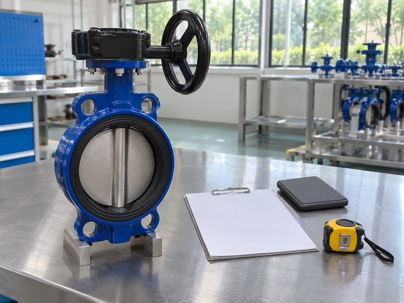
Work through one stated example
Assume Q = 40 m³/h, SG = 1.00, and an available valve pressure drop of 0.25 bar for a clean liquid satisfying those assumptions. The required Kv is 40 × √(1.00 / 0.25) = 80. That value is a required coefficient at the operating point, so compare it with the selected valve’s coefficient at an approved disc angle rather than its full-open value alone.
- Use operating flow units consistently throughout the calculation.
- Separate available valve differential from total system pressure.
- Repeat the calculation for the other operating cases.
- Obtain a complete manufacturer sizing check before selection.
| Example input | Assumed value |
|---|---|
| Operating liquid flow | 40 m³/h |
| Specific gravity | 1.00 |
| Valve differential | 0.25 bar |
| Required Kv | 80 |
The calculated coefficient identifies a sizing target; it does not establish cavitation clearance or guarantee controllability.
4. Why does disc angle change control behavior?
Disc angle changes flow area and resistance, but the resulting flow also depends on how pressure drop changes through the installed system. A catalog characteristic describes the valve under defined test conditions. The installed characteristic includes the pump, piping, branches, and changing system resistance. You cannot assume that half travel produces half flow or that a chosen angle range works for every butterfly design.
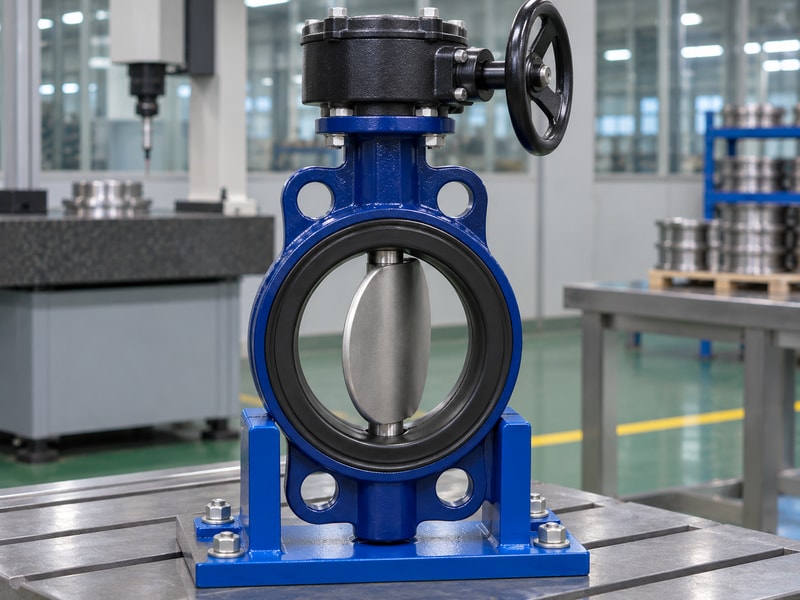
Check valve authority at the design point
Valve authority describes the valve’s share of the relevant circuit pressure loss under a stated definition and design condition. Agree on that definition when comparing calculations. A valve with very little available differential may pass the flow but provide weak control, while excessive differential wastes pumping energy and can create hydraulic damage.
- Plot required coefficient against the actual valve curve.
- Check minimum flow above the approved near-seat region.
- Reserve suitable travel for changing process conditions.
- Review system pressure losses at the selected design point.
| Selection symptom | Review needed |
|---|---|
| Minimum flow near closure | Oversizing and positioning resolution |
| Normal flow near full open | Capacity margin and authority |
| Large flow change per small movement | Installed gain and loop response |
Ask for predicted operating positions at all cases so you can review the usable range before commissioning.
5. How do pressure recovery and cavitation matter?
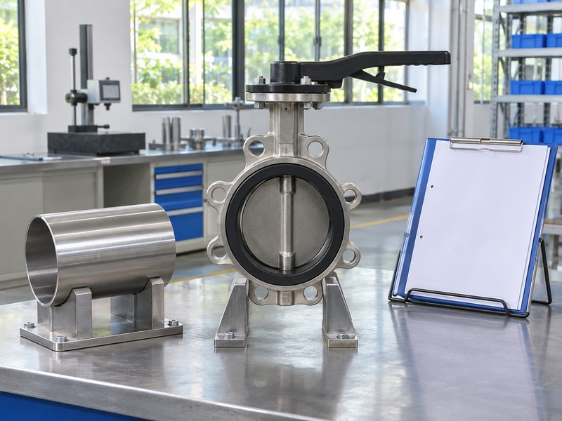
Pressure recovery determines how low local pressure falls inside the valve before recovering downstream, which can expose a liquid to cavitation or flashing. Upstream pressure minus downstream pressure alone cannot describe that local minimum. Cavitation occurs when vapor forms and subsequently collapses as pressure recovers; flashing persists when downstream conditions keep the fluid in a vapor-containing state. Both require a hydraulic review beyond the simple Kv estimate.
Obtain design-specific recovery data
Emerson’s Control Valve Handbook is a manufacturer reference for control-valve sizing, characteristics, and associated engineering checks. Use the selected valve’s pressure-recovery data and the fluid’s operating vapor pressure in the actual calculation. A durable seat compound cannot prevent damage caused by an unsuitable throttling pressure regime.
- Check absolute inlet and outlet pressures at each case.
- Use the correct recovery factor for the valve and travel.
- Include reducers and other relevant piping effects.
- Review noise, vibration, velocity, and damage limits.
| Pressure condition | Required review |
|---|---|
| Local vapor formation with recovery | Cavitation severity and limits |
| Persistent vapor downstream | Flashing and material/design suitability |
| High valve differential | Choking and mechanical loading |
Where the proposed valve cannot meet these limits, change the pressure distribution or review a more suitable control-valve design.
6. Which actuator and positioner checks are needed?
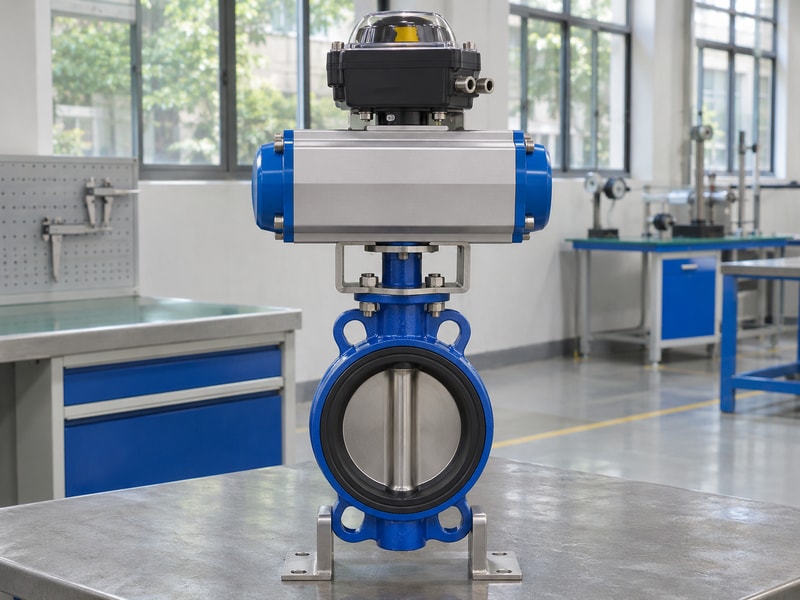
The actuator and positioner must move and hold the disc accurately against seating friction, dynamic fluid torque, and changing process differential. A high nameplate actuator torque does not establish small-signal control performance. Check output across travel at minimum supply, including spring-return operation where used. Also compare maximum available torque with the valve stem, coupling, and mounting limits so the drive cannot overload the assembly.
Review movement around the operating point
Specify acceptable deadband, resolution, response, and cycling duty for the process rather than choosing accessories by signal type alone. Shaft play, bracket flexibility, and seat friction can make the disc move differently from the command. Establish fail action and travel time from the system requirements, including possible pressure transients.
- Request breakaway, seating, and dynamic torque across travel.
- Check actuator output at the lowest operating supply.
- Confirm position feedback reflects actual valve movement.
- Review duty cycle, ambient conditions, and mounting stiffness.
| Assembly feature | Control implication |
|---|---|
| Deadband and friction | Delayed or uneven response |
| Dynamic torque | Holding and movement capability |
| Fail action and speed | Process condition after supply loss |
Witness a functional response test when the required positioning performance cannot be established from the proposed assembly’s records.
7. What does the FKM seat add to the review?
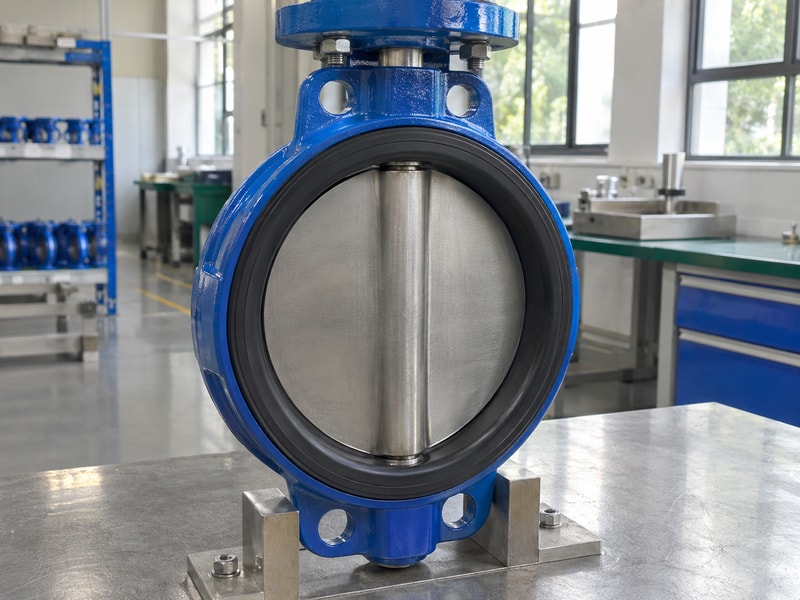
The FKM seat adds compound compatibility, friction, wear, and retention questions to the throttling review. Flow passing a partly open disc can load the seat differently from a fully open or closed valve. Ask whether the proposed seat construction supports the expected differential, velocity, position, and cycle count. FPM or FKM identifies a material family; the actual formulation and molded geometry remain controlled selection details.
Include exposure and movement in the assessment
Give the supplier the full fluid mixture and cleaning schedule, then identify how often the valve moves and where it normally operates. A chemical assessment based on a static sample does not establish the installed seat’s wear life. Track any proposed compound change because altered hardness or friction can also change actuator requirements.
- Confirm all wetted materials for process and cleaning fluids.
- Obtain approval for continuous partial-opening duty.
- Ask about minimum operating angle and velocity restrictions.
- Define replacement criteria for leakage, wear, or rising torque.
| Seat consideration | Evidence needed |
|---|---|
| Chemical exposure | Compound-specific assessment |
| Throttling loads | Manufacturer approval for exact construction |
| Repeated movement | Relevant cycling or service evidence |
For isolation alternatives, the wafer butterfly valve page describes connection and documentation requirements; confirm throttling capability separately for any proposed configuration.
8. How do you commission a throttling valve?
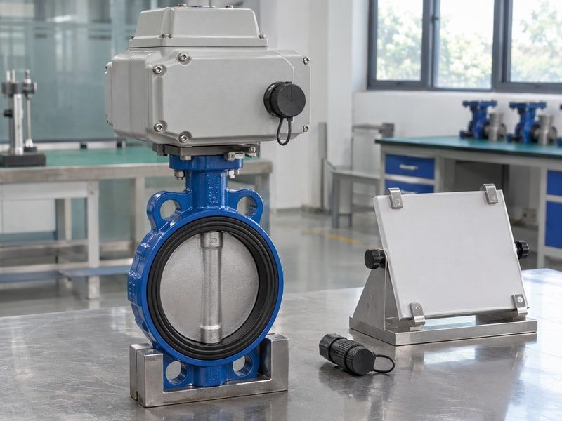
Commission a throttling valve by verifying installation and travel, then checking controlled response under agreed process conditions. Confirm the actual disc position, signal scaling, direction of action, and fail position before placing the loop in automatic operation. A positioner calibration can establish travel endpoints without proving that the selected valve controls minimum flow. Record process measurements as well as the control signal during response checks.
Compare the installed response with the sizing basis
Use stable, authorized test conditions and change the command in agreed increments. Observe whether the valve moves smoothly in both directions and whether measured flow follows the expected installed characteristic. Persistent hunting may come from sizing, friction, measurement noise, process interaction, or tuning; identify the cause before changing controller settings repeatedly.
- Verify flow measurement and pressure instrument readings.
- Record command, position, flow, pressures, and temperature.
- Check small changes around the normal operating point.
- Investigate vibration, noise, unstable flow, and abnormal torque.
| Commissioning record | Purpose |
|---|---|
| Travel calibration | Confirms command and movement agreement |
| Process response | Checks useful control over required cases |
| Final settings | Preserves the accepted operating baseline |
Retain the results against the valve tag and repeat affected checks after changes to the actuator, pump, piping, or control strategy.
9. When should another valve design be reviewed?
Review another design when the butterfly valve cannot provide the required control range, hydraulic limits, shutoff behavior, or positioning performance. A wide flow turndown, persistent cavitation, severe erosion, or operation near the seat may justify a different control element. Compare complete installed solutions, including pressure loss, piping modifications, actuation, and maintenance access. A smaller butterfly valve with reducers also needs its own hydraulic and mechanical assessment.
Match the alternative to the actual duty
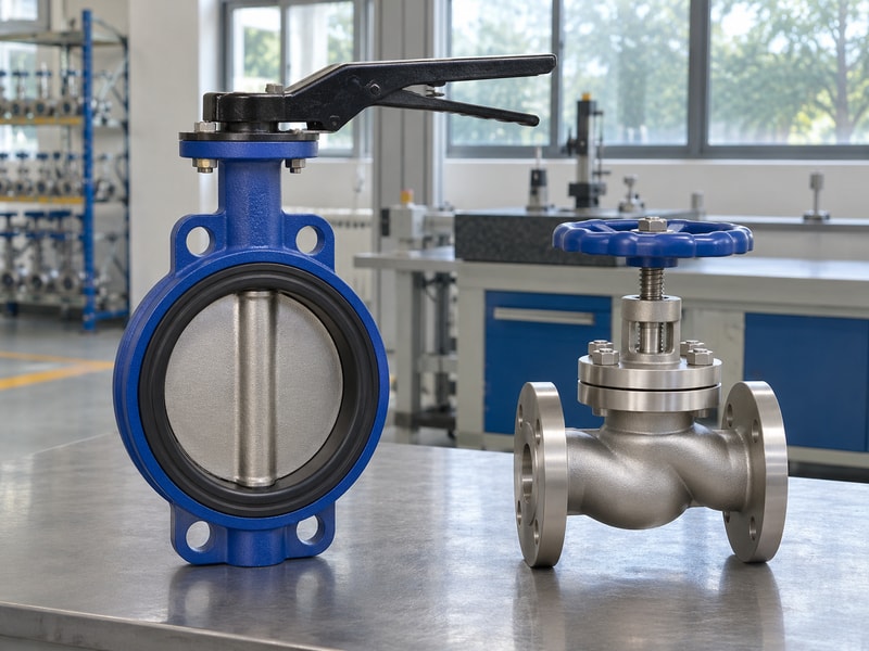
RUITO’s globe valve page describes another valve construction to review, but an isolation globe valve is not automatically a characterized control valve. For a fixed hydronic balancing requirement, a static balancing valve serves a different purpose from continuous automatic modulation. Specify the intended function before comparing products.
- Ask for operating positions and limits for each candidate.
- Compare available differential with required control performance.
- Review noise, erosion, leakage, and maintenance requirements.
- Confirm the exact trim and actuation offered for control duty.
| Unresolved requirement | Next engineering step |
|---|---|
| Minimum flow too close to closure | Review size or characterized trim |
| Cavitation exceeds limits | Review pressure staging or design |
| Poor positioning response | Review complete actuator-valve assembly |
Request written exceptions with each proposal so a lower price does not conceal an unmet operating case.
10. What do engineers ask about butterfly flow control?
Q1: Can I use any FKM-seated butterfly valve for throttling?
No. Obtain approval for the complete construction under the proposed differential, operating positions, velocity, and cycling duty. Chemical resistance alone does not establish throttling capability.
Q2: Can I size the valve from maximum flow alone?
No. Minimum and normal flow can reveal poor positioning range or oversizing that a maximum-flow capacity check misses.
Q3: Can I apply the simple liquid Kv formula to gas?
No. Gas sizing needs its own compressible-flow method and inputs. Two-phase and viscous liquid duties also require appropriate methods and corrections.
Q4: How do I know whether cavitation is acceptable?
Obtain a design-specific calculation and manufacturer limits. Required inputs include absolute pressures, fluid vapor pressure, recovery characteristics, travel, and relevant piping effects.
Q5: What should I send for a flow control review?
Send all operating cases, fluid properties, piping layout, performance requirements, and actuation details when you contact us. Request explicit confirmation of the proposed valve’s continuous control capability.