
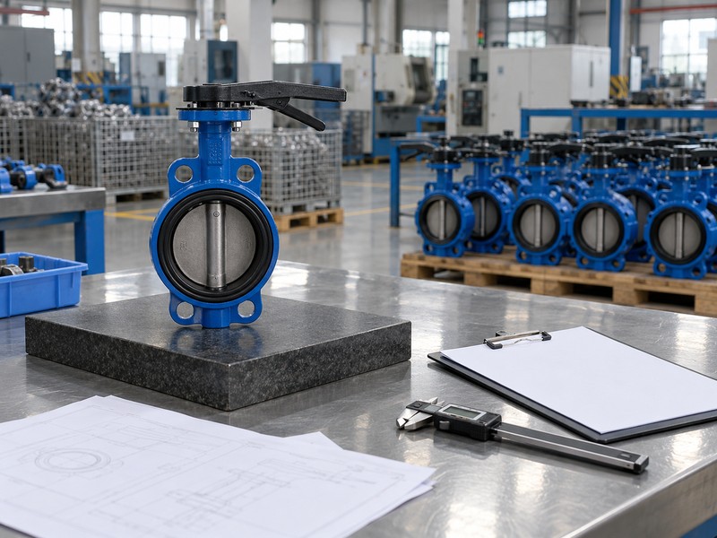
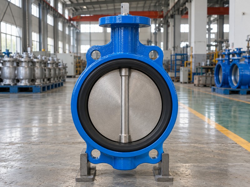
A butterfly valve usually has a short round body, a rotating disc and a lever, gearbox or actuator above the shaft. If a plant photo leaves you asking "what does a butterfly valve look like", trace the body and shaft before guessing from paint colour. A replacement still needs a drawing and material check.
1. What does a butterfly valve look like from the pipe end?
Viewed through an accessible pipe end, a butterfly valve has one disc mounted on a shaft inside a generally circular passage. A closed disc covers most of that passage, while an open disc presents a much narrower edge to the viewer. The shaft and disc remain in the flow path. That combination helps distinguish the valve from an empty spool or a full-port ball-valve bore.
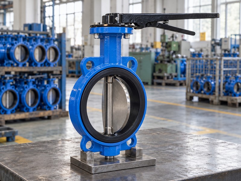
Which visual clues are dependable?
Look for the disc, the shaft connection and the short body together rather than treating any one feature as proof. A photo taken from an angle can make a partly open disc appear oval or conceal its edge behind the shaft. Protective covers and insulation can hide the bore entirely. Do not remove a cover or inspect an internal passage until the equipment is under the site's approved isolated, depressurized maintenance conditions.
- Identify one disc rotating around a shaft.
- Check the body from more than one safe viewing angle.
- Record obscured details as unknown rather than guessing.
| Visible feature | Possible interpretation | Confirm with |
|---|---|---|
| Round disc across the bore | Butterfly-type closure | Assembly drawing and shaft layout |
| Narrow edge in the passage | Disc may be near fully open | Approved travel reference |
| Plain circular cover | Shipping or maintenance protection | Valve identification and records |
2. How do the shaft and disc help identify the design?
The shaft provides the axis around which the disc rotates, but its relationship to the seat varies by design. In a concentric valve, the shaft axis passes through the central disc region and the bore centre. Offset designs move those relationships. A front photograph can hide the amount or direction of an offset, so visible symmetry alone cannot establish whether a valve has zero, two or three offsets.
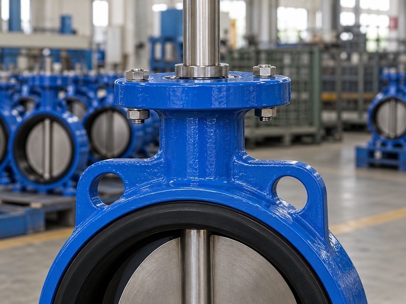
Can you identify offset geometry from a photograph?
A photograph can suggest a design family, but use a section drawing for the actual geometry. The shaft may sit behind the visible disc face, and the sealing surfaces can be difficult to distinguish from a retaining ring. For a replacement enquiry, photograph the neck, drive connection and body outline, then match those images to the manufacturer's approved drawing. Avoid assigning a high-performance or triple-offset classification solely because the disc looks thick or metallic.
- Separate a visible shaft feature from a verified offset dimension.
- Look for the seat and seal arrangement on the drawing.
- Ask for the exact model when internal geometry is hidden.
| Observation | What it can suggest | What remains unresolved |
|---|---|---|
| Shaft across disc centre | A concentric arrangement | Exact seat and service rating |
| Shaft behind disc face | An eccentric arrangement | Number and dimensions of offsets |
| Metallic perimeter ring | A seal or retaining feature | Sealing geometry and leakage class |
3. How does a wafer body differ visually from a lug body?
A wafer body is usually thin and often has a few plain centering ears, while a lug body has threaded bosses around its perimeter. Through-bolts normally clamp a wafer valve between both pipe flanges. Bolts enter a lug body's threaded bosses from each side. These fastening arrangements are more useful identification clues than paint colour, handwheel size or the shape of the actuator enclosure.
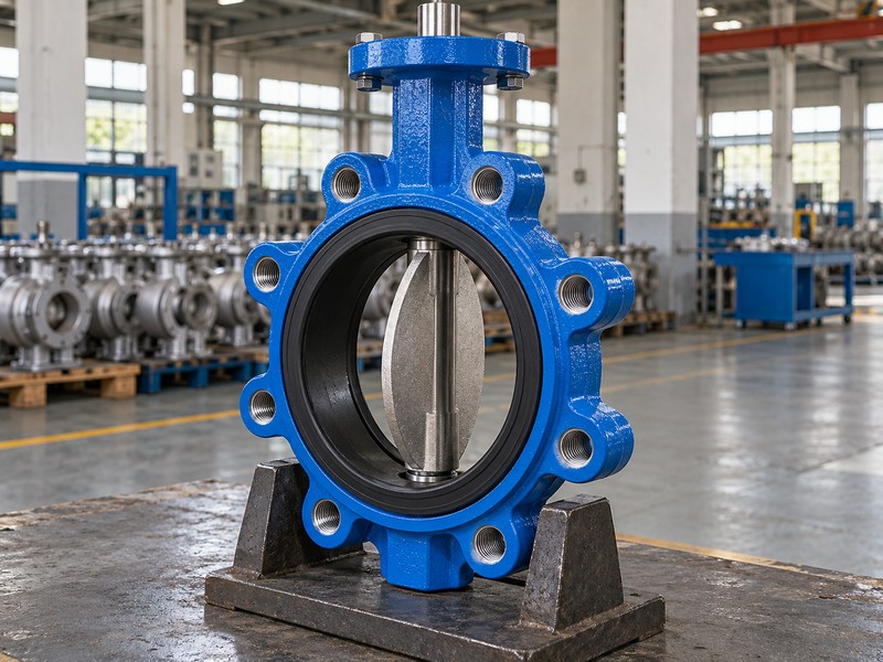
Why should you check the threads?
Photographs can make plain holes look threaded or hide bosses behind pipe flanges. Check an accessible approved drawing for the hole pattern, thread specification and required engagement. Our lug butterfly valve page describes a body style that needs its own interface review. Lug appearance does not prove end-of-line capability; that duty needs a separate declared rating for the exact size, material set and installation arrangement.
- Distinguish plain centering holes from load-bearing threaded bosses.
- Record bolt pattern and face-to-face length separately.
- Check end-of-line permission in the product documents.
| Body style | Typical visible clue | Document check |
|---|---|---|
| Wafer | Thin body and plain centering ears | Through-bolt clamping arrangement |
| Lug | Threaded bosses around the body | Thread, engagement and loading limits |
| Body hidden by flanges | Fasteners partly conceal the interface | Exact interface drawing |
4. What does a double-flanged butterfly valve look like?
A double-flanged butterfly valve has a separate pipe-connection flange at each end of its body. A side view should show two flange faces and the body between them. Each end bolts to the corresponding pipe flange. A front view alone may look like one large ring, so it can conceal the connection length and make a flanged valve look more like a wafer assembly.
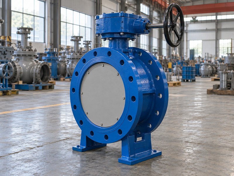
Which dimensions do photographs fail to show?
Perspective can distort face-to-face length, bolt-circle diameter and the distance from the pipe centreline to the drive. Do not scale a photograph to create a replacement drawing. Compare the flanged butterfly valve arrangement with the approved general arrangement and mating pipe details. A U-type or another short flanged body may have a different structure and length, even when its overall silhouette appears similar.
- Photograph the side profile as well as the end face.
- Record both flange standards and the face-to-face length.
- Check the complete drive envelope and maintenance clearance.
| View | What it reveals | What needs a dimension |
|---|---|---|
| Front | Bore and bolt-hole arrangement | Bolt circle and hole diameter |
| Side | Two end flanges and body length | Approved face-to-face length |
| Top | Drive and mounting arrangement | Height and service clearance |
5. Which features identify a grooved-end butterfly valve?
A grooved-end butterfly valve has pipe-like cylindrical ends prepared for a compatible grooved coupling system. You should see the grooved connection arrangement rather than a wafer body's centering ears or a full flange bolt circle. Protective caps may hide the groove itself. In an installed line, the surrounding coupling housings can also conceal much of the valve end.
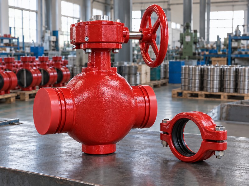
Does a red body or switch prove fire-service approval?
No. Colour and accessories are visual clues rather than approval documents. Confirm the exact model, size, coupling system and required supervisory equipment before describing the valve as approved for a fire-water installation. Our grooved-end butterfly valve configuration has an interface that must match pipe outside diameter, groove profile, gasket and coupling. Similar-looking housings can belong to different connection systems with different limits.
- Check pipe outside diameter and the specified groove profile.
- Identify the coupling and gasket separately from the valve.
- Verify any required approval and supervisory documentation.
| Visual clue | Useful observation | Further confirmation |
|---|---|---|
| Cylindrical prepared ends | Likely a grooved connection | Groove dimensions and pipe system |
| Two-bolt coupling housing | Mechanical joint around the ends | Coupling type and gasket |
| Red paint or switch box | Possible service or accessory clue | Exact approval and wiring documents |
6. What can a lever or gearbox tell you?
A lever suggests direct local operation, while a gearbox and handwheel provide mechanical reduction between the operator and valve shaft. These drives can help you locate the shaft axis and estimate the space needed for access. They do not establish the seat material, pressure rating or internal offset geometry. A large handwheel can serve a high-torque duty on more than one valve design.
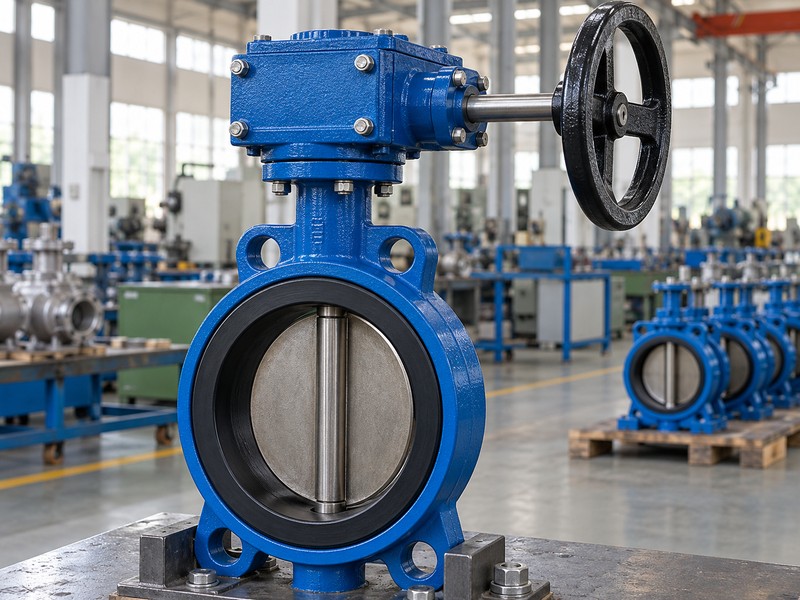
Can you trust the external position indicator?
Treat an indicator as a commissioned reference that needs verification after assembly or maintenance. A lever, pointer or limit switch can be fitted with the wrong indexing, especially after the drive has been changed. Check the manufacturer's travel reference and the recorded commissioning results before assuming that a pointer shows actual disc position. A photograph cannot establish whether the valve is fully seated or whether a drive stop has been set correctly.
- Locate the valve shaft and the gearbox input shaft separately.
- Check the approved opening direction and travel reference.
- Keep position indication separate from proof of tight shutoff.
| Drive feature | What it can show | What it cannot prove |
|---|---|---|
| Manual lever | Local operating arrangement | Seat material or tight closure |
| Gearbox and wheel | Mechanical reduction and access needs | Internal offset geometry |
| Pointer or limit switch | Configured position reference | Correct indexing without verification |
7. Can you identify seat and disc materials by colour?
You cannot reliably identify a seat compound or disc grade from colour alone. Black rubber may be EPDM, NBR or another formulation, while a bright metal surface does not establish a particular stainless grade. White fluoropolymer components can also have different constructions. A visible liner does not prove that every wetted surface, backing material and shaft seal has the same chemical resistance.
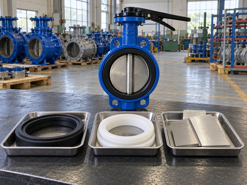
What evidence should replace a visual guess?
Match the material list, part identification and traceable supply records to the exact valve. For a lined assembly, distinguish the body liner from the disc covering and check the extent of wetted-metal isolation. For a repair, confirm the spare-seat drawing and compound rather than buying a ring that looks similar. Two seats can share the same colour and approximate diameter while differing in interference, retention and flange-sealing dimensions.
- Use material grades and compound specifications rather than colour names.
- Review body lining and disc covering separately.
- Match spares to the approved drawing and revision.
| Appearance | Unsupported assumption | Better evidence |
|---|---|---|
| Black elastomer seat | All black seats have the same resistance | Exact compound specification |
| Bright metallic disc | The alloy suits the intended medium | Material grade and traceable certificate |
| White liner or covering | The entire valve is fully lined | Wetted-surface drawing and material list |
8. Why is the actuator alone a poor identification guide?
The same general type of rotary actuator can operate a butterfly valve, a ball valve or another quarter-turn device. An enclosure can hide the shaft connection and make two different valve bodies look alike from above. Pneumatic or electric actuation also says little about the internal seat. Identify the valve body and closure mechanism before assigning a type from the attached drive.
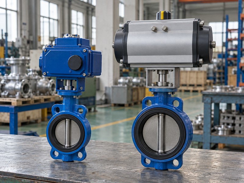
How do you compare a hidden valve with another type?
Use the approved assembly drawing to confirm whether the closure is a rotating disc, a bored ball, a rising gate or an automatic check element. A butterfly valve's disc stays in the bore, whereas a full-port ball valve presents its bored passage when open. Gate and check valves have different motion and function. When insulation or a crowded skid obscures the body, record the uncertainty and request the valve tag and drawing instead of removing equipment for a visual guess.
- Trace the actuator connection to the actual valve body.
- Check the closure mechanism on the section drawing.
- Do not infer fail action from actuator shape alone.
| Observed item | Possible ambiguity | How to resolve it |
|---|---|---|
| Quarter-turn actuator | Butterfly or ball-valve package | Closure and body drawing |
| Large insulated assembly | Body and stem arrangement hidden | Valve tag and approved records |
| Pneumatic cylinder | Spring-return or double-acting construction | Actuator data and failure-action test |
9. What should you record before ordering a replacement?
Record the manufacturer, exact model, valve tag, nominal size, connection standard, face-to-face length and drive details before seeking a replacement. Add service pressure, temperature, medium and the required closing differential. Photographs help explain the enquiry but cannot replace controlled dimensions or material data. A visually similar valve can fit poorly, interfere with the pipe bore or have a different service limit.
How do you turn pictures into a useful enquiry?
Send front, side and drive views alongside the approved drawing or verified dimensions. ISO's metallic butterfly-valve standard separates product design and rating requirements from the visual features of a particular unit. Mark any unknown material or dimension clearly so the supplier can resolve it. For a RUITO replacement review, contact us with those records and the actual duty; engineering can compare the proposed valve with the installation rather than choose from a photograph alone.
- Capture readable identification without exposing unrelated site information.
- Measure only within the site's approved maintenance procedure.
- Record unknown values and open technical deviations.
| Record | Useful detail | Why it matters |
|---|---|---|
| Identity | Manufacturer, model and tag | Finds the correct design records |
| Interface | Flange, bore, length and drive dimensions | Checks physical compatibility |
| Duty | Medium, temperature and pressure cases | Checks material and operating limits |
10. What do buyers ask when identifying a butterfly valve?
Q1. Can I identify a butterfly valve without opening the pipe?
Often you can identify a likely family from the body, tag and drawings. Confirm the exact model from records when internal parts are hidden. A photograph alone may leave the seat, offset geometry and service rating unresolved.
Q2. How do I know if a valve is wafer or lug type?
Check the fastening arrangement. A wafer body normally relies on through-bolts across both pipe flanges, while a lug body has threaded bosses. Use the interface drawing when installed flanges hide those features.
Q3. Can a black seat tell me whether it is EPDM or NBR?
No. Both compounds can appear black, and formulations within a material family can differ. Confirm the exact approved compound and part identification before assessing compatibility or buying a spare.
Q4. What is the best photo for a replacement enquiry?
Send several views rather than one image. Include the identification plate, front and side body views, connection details and drive arrangement. Add verified dimensions and the service data so the supplier can check the proposed replacement.
Q5. Can I infer pressure rating from the flange size?
No. A flange pattern is only one part of the identification. Confirm the complete valve's pressure-temperature rating, seat differential limit, direction and connection limits from the exact product documents.