
A double offset butterfly valve places the shaft away from both the seat plane and the pipe-bore centreline. Those two offsets create a cam-like movement that reduces seat rubbing during much of the stroke. The answer to "what is a double offset butterfly valve" still leaves a buyer with separate checks for sealing, direction and drive torque.
1. What is a double offset butterfly valve?
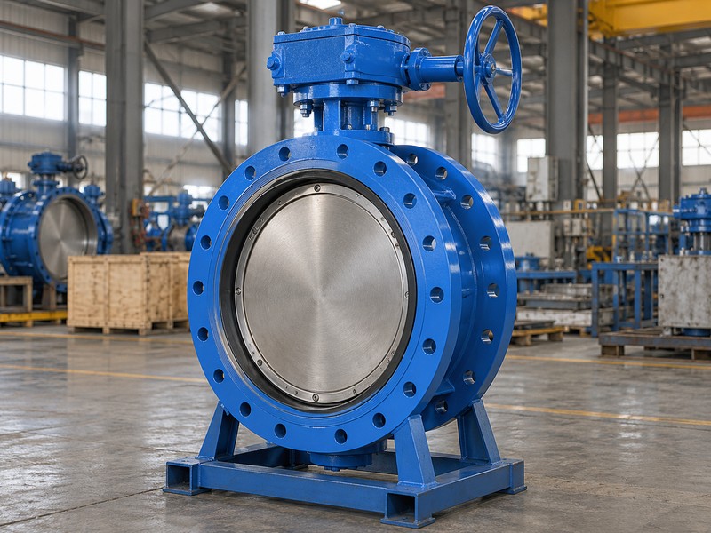
A double offset butterfly valve is an eccentric disc valve with two defined shaft offsets. One separates the shaft axis from the sealing plane, while the other separates it from the bore centreline. The resulting motion allows the disc seal to move away from the body seat as the valve opens. A section drawing should show those relationships and the actual sealing parts for the model being supplied.
What does the name leave unspecified?
Double offset describes geometry rather than a complete material or service specification. The valve can have different body connections, seal materials, pressure limits and actuation packages. Do not treat the term as a promise of metal seating, equal shutoff in both directions or a particular temperature capability. Ask the supplier to identify the body seat, disc seal, retaining parts and shaft arrangement on one approved assembly drawing.
- Locate both offsets on the section drawing.
- Identify which component carries the flexible or metallic seal.
- Match geometry, materials and rating to the same exact model.
| Design feature | Meaning | Separate check |
|---|---|---|
| Offset from sealing plane | Shaft and seal plane are separated | Actual seat and disc-seal construction |
| Offset from bore centre | Shaft axis is displaced across the bore | Dimensions and direction of movement |
| Quarter-turn operation | Disc rotates between travel limits | Torque, stops and approved stroke |
2. How do the two offsets change seat contact?
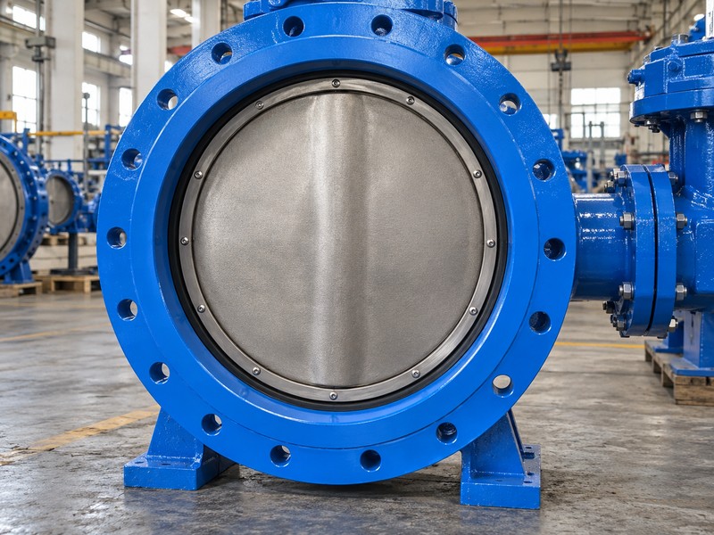
The two offsets let the disc seal lift away from the seat after the valve begins opening, reducing rubbing over much of its travel. Contact still occurs near closure, and the seal must receive the intended seating load. The exact contact interval depends on the design. A fixed claim that every double offset valve rubs for the same number of degrees is not a substitute for the model's geometry and test evidence.
Does reduced rubbing guarantee a longer service life?
Reduced rubbing can address one wear mechanism, but seat life also depends on the fluid, solids, alignment, temperature and closing conditions. A damaged seal, bent shaft or mis-set stop can defeat the intended motion. Review the seal-retaining arrangement and the supplier's cycling evidence under relevant conditions. If a seat is replaceable, the spare must match the approved profile, material and fastening details rather than merely fit the disc diameter.
- Check contact and clearance through the intended travel.
- Confirm stop settings from the approved instructions.
- Review cycle evidence and service conditions together.
| Condition | Effect on sealing | What to review |
|---|---|---|
| Seal lifts away during opening | Reduces sliding contact | Model-specific cam geometry |
| Disc approaches closure | Applies the required seating load | Torque and travel-stop settings |
| Solids or damaged sealing surface | Can prevent correct contact | Medium limits and inspection findings |
3. How does it differ from concentric and triple offset?
A concentric valve centres the shaft and disc within its sealing arrangement, while a double offset valve displaces the shaft in two defined ways. A triple offset design adds an angular relationship to the conical sealing geometry. These categories describe different seal motions. They do not establish an interchangeable seat, drive or connection length.
Can one design replace another without a new review?
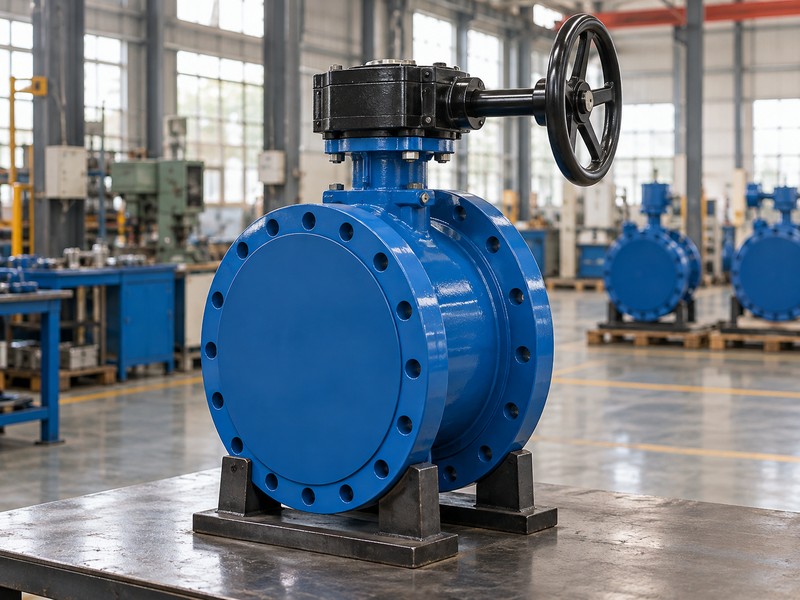
A replacement needs a comparison of the complete interface and operating cases. For example, a wafer butterfly valve and a large double-flanged water valve may share a nominal bore but use different fastening and installation lengths. Likewise, a metal-seated triple offset package has its own leakage and seating-torque requirements. RUITO's stated large double-eccentric water-valve range should not be treated as evidence of an unlisted triple offset or high-temperature product range.
- Compare seal motion separately from body connection.
- Check face-to-face length, bore clearance and drive interface.
- Confirm the proposed design is within the supplier's actual scope.
| Geometry family | General sealing distinction | Do not assume |
|---|---|---|
| Concentric | Centred disc with its specified seat interaction | Suitability for every throttling duty |
| Double offset | Cam-like separation from the seat | Metal seating or equal directional rating |
| Triple offset | Offset conical sealing geometry | Unlimited temperature or universal tightness |
4. Where does a large double offset water valve fit?
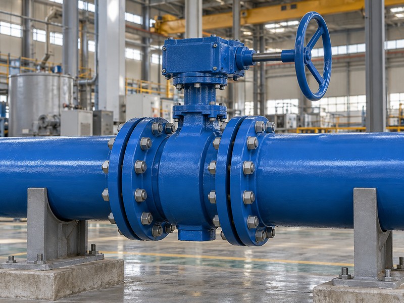
A large double offset butterfly valve can isolate water mains, pump-station lines and treatment-plant sections when its approved rating and hydraulic behaviour suit the system. Its quarter-turn movement can fit applications where a rising-stem envelope would be awkward. Large size also brings higher handling loads and greater consequences from a poor closure schedule. Review the valve as part of the actual pipeline rather than as an isolated catalogue item.
Which RUITO limits need to stay with the model?
RUITO's stated double-flanged double-eccentric water-valve range is DN350–3000 with PN10 or PN16 configurations. Each size and material set still needs its own pressure-temperature and directional closure data. A water and wastewater project should also define fluid cleanliness, solids, flow, surge and required isolation cases. Drinking-water contact approval is a separate review covering the exact wetted materials, size and temperature range.
- State forward and reverse closing cases separately.
- Give normal flow, pump operating cases and surge information.
- Provide installation access, lifting and maintenance constraints.
| Project input | Why it matters | Supplier response |
|---|---|---|
| Line size and interface | Controls physical fit and handling | Approved general arrangement and mass |
| Pressure and transient cases | Controls body and closure duty | Rated operating envelope |
| Fluid and contact requirements | Controls materials and approvals | Exact material list and relevant evidence |
5. Why can forward and reverse shutoff ratings differ?
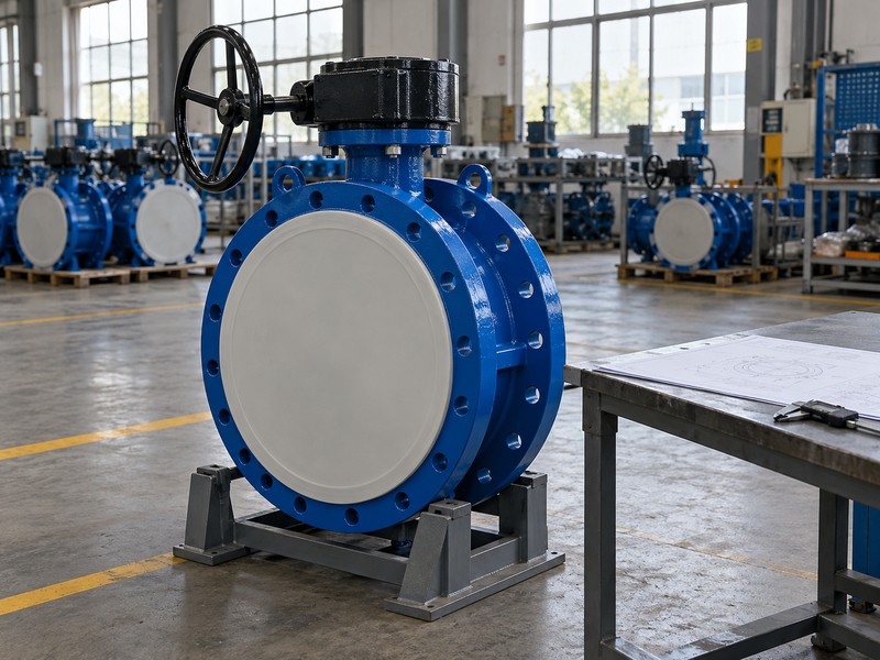
Forward and reverse shutoff ratings can differ because pressure acts differently on an eccentric disc, seal and supporting parts. A preferred direction may help the seal seat, while reverse pressure can impose a different load. Flow capability in either direction does not establish equal shutoff differential in both directions. The drawing and data sheet must identify the direction associated with each declared closure limit.
How should you record directional limits?
Put the actual maximum differential for each direction in the enquiry and purchase specification. In a documented RUITO DN2400 PN16 water-valve case, the stated project closing limits were 10 bar forward and 6 bar reverse. Those figures belong to that defined configuration and project. A different size or seal arrangement needs its own declaration, and a PN16 body designation should not be used to overwrite a lower reverse-closure limit.
- Mark the approved pressure direction on the drawing.
- Check reverse pressure during shutdown and maintenance cases.
- Require reports to identify the tested direction and criterion.
| Term | What it describes | Required distinction |
|---|---|---|
| Body pressure rating | Pressure-boundary capability at stated conditions | Separate from disc shutoff differential |
| Forward closure limit | Allowed differential in the stated direction | Linked to model and temperature |
| Reverse closure limit | Allowed differential from the opposite side | May be lower than the forward limit |
6. Which seal, seat and coating details matter?
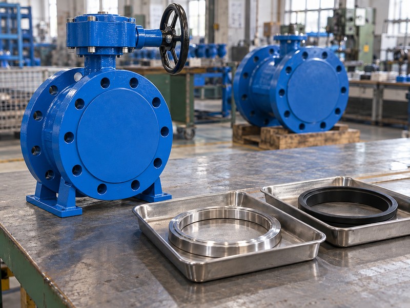
The disc seal, body seat, retaining parts, shaft seals and coating system all need to match the water and operating conditions. A replaceable elastomer ring can provide the closure seal against a metal seat, but its compound and retention are design-specific. The coating protects selected surfaces and does not replace a corrosion review of the actual wetted metals. Drinking-water contact requirements also cover more than the main rubber seal.
What should you ask about a replacement seal?
Request the approved profile, compound, joint arrangement and retaining-fastener details. Check whether the replacement requires a particular assembly position, fastening sequence or verification test. A visually similar ring can change seating load and the point at which the seal disengages. For water containing treatment chemicals or glycol, review the exact fluid composition and temperature against the complete wetted material list before accepting a nominally equivalent seal.
- Identify the disc seal and body seat as separate parts.
- Confirm compound and retaining details for replacement seals.
- Review coating, shaft seals and exposed metals together.
| Component | Useful specification | Check against |
|---|---|---|
| Disc seal | Profile and exact compound | Fluid, temperature and seating geometry |
| Body seat and retaining parts | Grade, finish and fastening details | Corrosion and mechanical loads |
| Coating and shaft seals | Approved system and material scope | Water chemistry and contact requirements |
7. How should you select the gearbox or actuator?
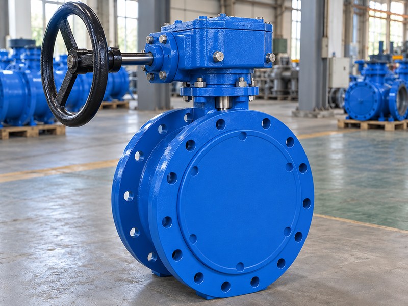
Select the drive from the valve's required torque through the full stroke under the specified operating cases. Seat breakout, running movement and final seating can have different requirements. Fluid-induced torque also changes with disc position and differential pressure. A large motor or gearbox does not automatically provide a suitable package if its output can overload the shaft or if its travel settings prevent correct seating.
Which drive data belong in the approval?
Compare the required valve-torque curve with the drive's available output at minimum supply conditions. Then check maximum output against the shaft and mounting limits. The approved closure time should come from the pipeline's transient review, especially near pumps and long water mains. Confirm the coupling, bracket, position indication and local operating access, and test the assembled package against actual disc travel before release.
- Use the complete torque curve rather than one catalogue value.
- Check minimum supply and maximum drive output.
- Coordinate closing time with the pipeline design.
| Drive check | Input | Acceptance question |
|---|---|---|
| Available torque | Minimum energy-supply condition | Can the drive complete the required stroke? |
| Maximum output | Drive torque limit and settings | Can the valve shaft and mounting withstand it? |
| Travel and speed | Approved stops and closing schedule | Does movement match the system requirement? |
8. What installation and handling checks are needed?
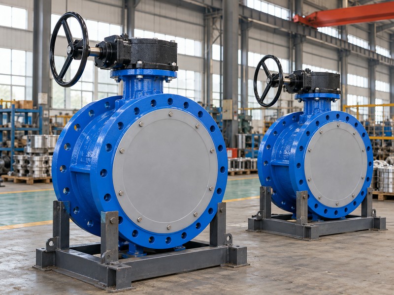
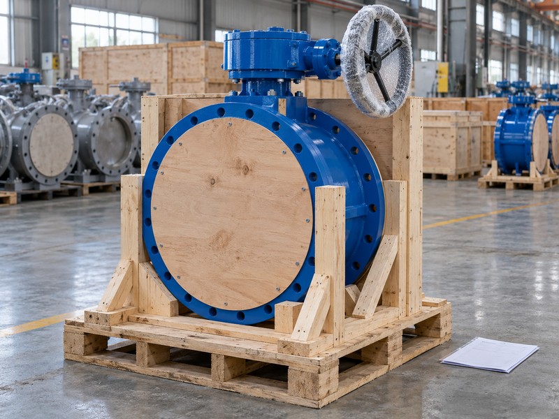
Check the flange interface, open-disc envelope, valve mass, centre of gravity, support arrangement and maintenance access before delivery. A matching nominal size leaves many of those details unresolved. Large valves need approved lifting points and handling instructions because the actuator and shaft are not general-purpose lifting attachments. Pipe supports and any dismantling joint must follow the project's restraint and installation design.
Can you install it from the flange drilling alone?
No. Review the complete flanged butterfly valve drawing, including face-to-face length and the disc's swept volume outside the body. Pipe lining, reducers or nearby equipment can obstruct the opening disc. Protect the sealing surfaces and avoid using the valve to pull misaligned pipes together. Record the approved lifting and support arrangement in the installation package so delivery, rigging and assembly teams use the same assumptions.
- Verify pipe bore and clearance through the full disc movement.
- Use declared mass, centre of gravity and approved lifting points.
- Confirm pipe restraint and maintenance-removal space.
| Installation item | Check before delivery | Possible problem avoided |
|---|---|---|
| Interface and disc envelope | Flange, bore and adjacent equipment | Disc interference or field rework |
| Handling arrangement | Mass, lifting points and support | Damage from incorrect load paths |
| Maintenance space | Drive access and removal envelope | An inaccessible installed valve |
9. Which inspection evidence should a buyer review?
Review pressure-boundary tests, direction-specific closure results, operating-torque checks and the approved dimensional records for the supplied configuration. The report should identify the product, procedure, test medium, pressure, direction and acceptance criterion. A generic certificate cannot show that the reverse-pressure case or the correct seal version was tested. Keep the product's permitted operating conditions separate from factory inspection pressures.
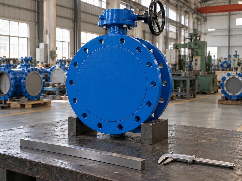
Why do large-valve test fixtures need their own review?
Test fixtures must withstand the reaction loads created by their actual effective pressure area. For example, a 2.6 m effective diameter at 24 bar produces approximately 12.74 MN of theoretical force on one restrained end, using force equals pressure times area. That is a fixture-load calculation rather than a working-pressure or operating-torque rating. Agree the relevant ISO 5208 or contract inspection method and contact us with the full duty and interface data for a RUITO engineering review.
- Link the drawing, material list and test record to the product ID.
- Identify the closure-test direction and accepted leakage criterion.
- Check fixture capacity, instrumentation and agreed witness points.
| Evidence | What to match | What it establishes |
|---|---|---|
| Dimensional record | Approved drawing and product ID | Checked interface and assembly dimensions |
| Pressure and closure report | Procedure, pressure and direction | Result under the stated inspection conditions |
| Torque and drive record | Valve and drive configuration | Function of the assembled operating package |
10. What do buyers ask about double offset butterfly valves?
Q1. Can I assume every double offset valve has a metal seat?
No. Double offset identifies geometry, while the sealing materials are separate choices. Check the disc seal, body seat and auxiliary seals on the exact material list and assembly drawing.
Q2. How do I know which pressure direction is preferred?
Use the approved product drawing and directional data. Match any body marking with the declared forward and reverse closure limits. Do not infer pressure capability from the apparent direction of a disc or shaft.
Q3. Can I replace a concentric valve with a double offset valve?
Only after reviewing the complete substitution. Compare connection length, flange details, bore clearance, materials, operating torque and directional limits. A shared nominal size does not establish interchangeability.
Q4. What is the best drive for a large water valve?
Choose from the required torque, closing schedule, supply conditions and operating access. A gearbox or powered actuator must match the valve and system. Check both available torque and the valve's allowable shaft load.
Q5. Can I use a water-valve double offset design for steam?
Only if a separately specified design and material set are approved for that steam duty. The stated RUITO large-water-valve range does not establish a general high-temperature or steam capability. Request the exact scope and supporting data.