
A butterfly valve is a quarter-turn valve that moves a disc across a pipe bore to stop or adjust flow. To answer "what is a butterfly valve" for a purchase order, check its disc, seat, pressure limits and drive together. A matching flange drawing alone cannot resolve those choices.
1. What is a butterfly valve and how does it stop flow?
A butterfly valve stops flow when its rotating disc meets a seat around the bore. Turning the shaft normally moves the disc through roughly 90 degrees between closed and fully open positions. In the open position, the disc plane runs approximately parallel to flow, although the disc and shaft still occupy part of the passage. That remaining obstruction means you should check the published flow coefficient rather than treat the valve as an empty length of pipe.
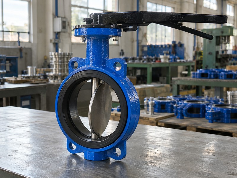
What changes during the quarter turn?
The actuator supplies torque through the shaft, while bearings guide the assembly and shaft seals contain the medium. Seat contact, pressure acting across the disc and moving fluid all affect the torque required. A valve that turns freely on a dry bench can need much more torque during service. Ask for operating torque at your actual closing differential pressure, including the stated direction and temperature, before choosing a drive.
- Confirm the direction of rotation and both travel limits.
- Check the disc position independently of the external pointer.
- Use a model-specific flow coefficient for pressure-drop calculations.
| Position | What the disc does | What to verify |
|---|---|---|
| Closed | Contacts the seat | Rated shutoff differential |
| Partly open | Restricts the passage | Approved throttling range |
| Fully open | Remains inside the bore | Flow coefficient and clearance |
2. Which butterfly valve parts should a buyer check?
A buyer should check the body, disc, shaft, seat, bearings and shaft seals as a complete assembly. The body carries pressure and provides the pipe connection, while the disc and seat form the closure. Depending on construction, the shaft may contact the medium or sit behind protective seals. A stainless disc alone tells you little about the corrosion resistance of the remaining wetted parts.
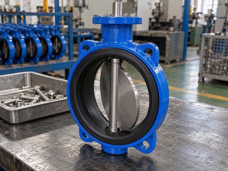
Which details belong in the material list?
Request a bill of materials that identifies each wetted component and the exact seat compound. For chemical duties, include the backing material, shaft seals and any lining that separates the medium from the body. Replacement parts must match the approved design and revision. An apparently similar seat can change disc interference, operating torque and flange sealing, so a generic rubber ring is a poor substitute for a confirmed spare.
- List body and disc material grades separately.
- Identify wetted shaft surfaces and auxiliary seals.
- Match spare seats to the approved drawing and compound.
| Part | Buyer question | Useful evidence |
|---|---|---|
| Body and disc | Which grades are supplied? | Material list and certificates |
| Seat and shaft seals | Which compound touches the fluid? | Controlled material specification |
| Shaft and bearings | Are loads and media exposure covered? | Assembly drawing and torque data |
3. How do wafer, lug and flanged connections differ?
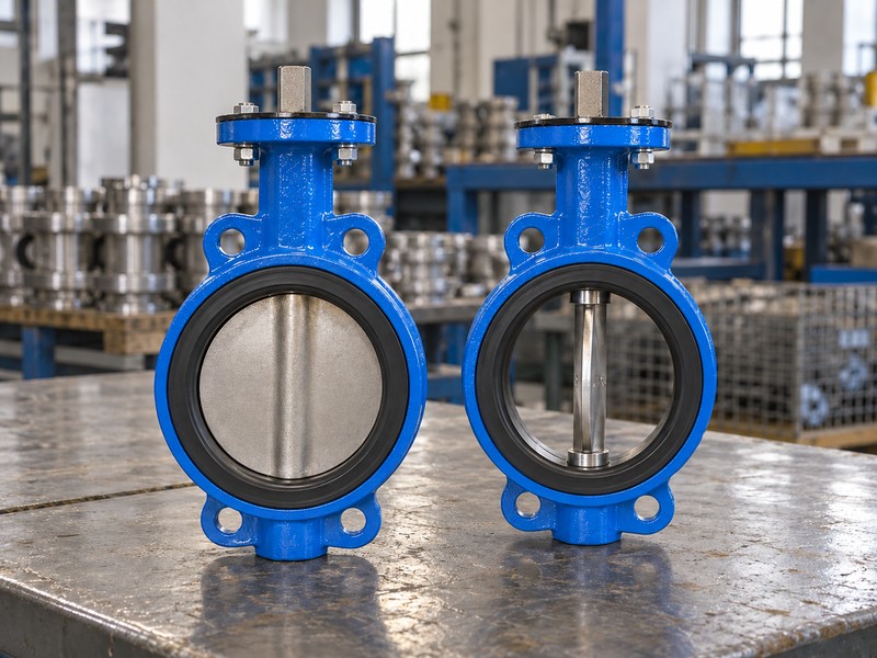
Wafer, lug and double-flanged bodies connect to piping in different ways. A wafer valve normally sits between two pipe flanges held together by through-bolts. A lug valve has threaded bosses that receive bolts from each side, while a double-flanged valve has separate end flanges. These connection names describe the body interface; they do not establish pressure direction, seat material or permission for end-of-line service.
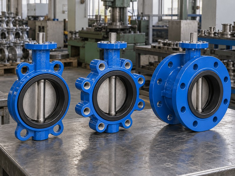
Can you replace one body style with another?
Compare face-to-face length, bolt-hole pattern, available bolt engagement and the open-disc envelope before agreeing to a substitution. Our wafer butterfly valve and lug butterfly valve pages describe separate connection options that require their own drawings. Lug construction can support certain approved end-of-line arrangements, but that capability needs a declared size, temperature and differential-pressure rating. Pipe supports must carry piping loads rather than transfer them through the valve body by assumption.
- Check both mating flange standards and actual internal diameters.
- Specify bolt lengths for the selected body style.
- Request a separate end-of-line rating when that duty is required.
| Connection | Typical fastening | Check before substitution |
|---|---|---|
| Wafer | Through-bolts across both flanges | Clamping and disc clearance |
| Lug | Bolts engage threaded bosses | Engagement and end-of-line limits |
| Double flanged | Each end bolts to its mating flange | Face-to-face length and supports |
4. Which seat material fits your actual medium?
The correct seat depends on the full medium composition and simultaneous operating conditions. EPDM is commonly selected for compatible water duties, while an approved NBR compound may suit particular mineral oils. PTFE or PFA linings serve different chemical applications when the complete wetted assembly has been reviewed. A material name does not establish resistance to every concentration, cleaning liquid, impurity or temperature.
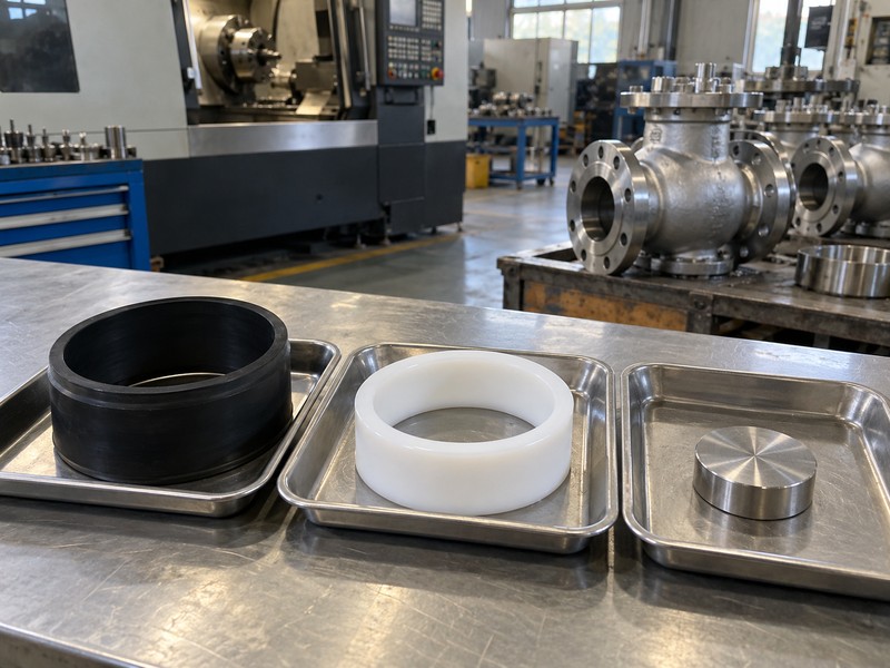
What information prevents a material mismatch?
Send the supplier normal and upset temperatures, concentration, contaminants, cleaning procedures and minimum absolute pressure. For lined valves, ask whether the disc alone is coated or whether the body passage is continuously lined as well. The PTFE lined butterfly valve configuration should be checked against its own backing, shaft seal and pressure-temperature limits. Do not transfer a chemical compatibility statement from a lining resin to every component in the finished assembly.
- State concentration and whether percentages are by mass or volume.
- Include cleaning media and exposure duration.
- Review backing and auxiliary seals alongside the main seat.
| Candidate material | Starting application | Check before approval |
|---|---|---|
| EPDM | Compatible water and selected glycol duties | Compound, additives and temperature |
| NBR | Selected mineral-oil duties | Oil formulation and swelling evidence |
| PTFE or PFA lining | Reviewed chemical-liquid duties | Continuous coverage and complete assembly limits |
5. How do pressure and temperature limit selection?
Pressure and temperature must remain within the rating of the same valve configuration at the same time. A PN16 designation does not mean every seat, actuator and service condition can withstand 16 bar across a closed disc. Body pressure, allowable shutoff differential and reverse-direction capability are separate checks. The lowest applicable limit across the valve, pipe connection and associated components controls the selection.
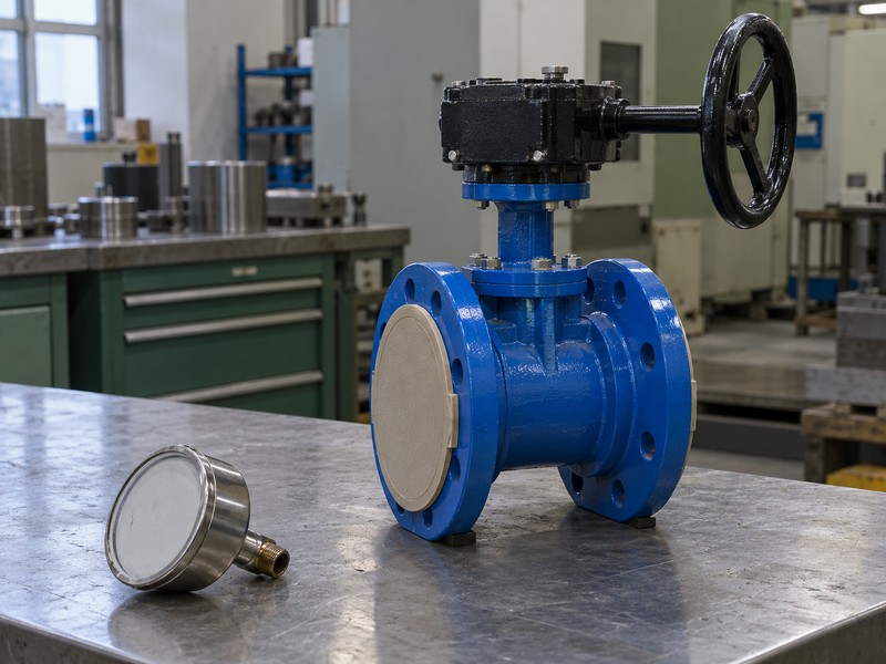
What does a test pressure prove?
A factory shell test checks the pressure boundary under a defined inspection procedure; it does not raise the allowed working pressure. For example, a specified PN16 water-valve configuration may have a 24 bar ambient shell test and a 17.6 bar closure test when the approved procedure and seat rating permit them. Those values remain test conditions. Ask for the operating pressure-temperature curve and direction-specific closure limits rather than inferring service capability from a successful pressure test.
- Provide maximum operating pressure and closing differential separately.
- Include surge conditions and reverse-pressure scenarios.
- Keep shell-test values separate from service ratings.
| Pressure term | What it describes | What it does not establish |
|---|---|---|
| Working pressure | Allowed service under stated conditions | All-temperature capability |
| Shutoff differential | Pressure difference across the closed disc | An identical rating in both directions |
| Shell-test pressure | An inspection condition | A new working-pressure rating |
6. What determines actuation and the failure position?
Operating torque, speed, available energy and the required response to energy loss determine the actuation package. A manual lever suits some smaller valves, while a gearbox reduces the force needed at a handwheel. Electric and pneumatic drives support remote operation. Their mounting pattern alone does not prove that the coupling, bracket, shaft strength and output torque are suitable for the selected valve.
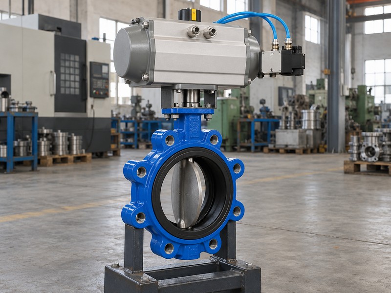
Will the valve reach the required safe position?
Define the required response separately for lost air, lost electrical power and a lost control signal. A double-acting pneumatic actuator normally needs an engineered arrangement if movement after air loss is required. A spring-return unit has its own torque curve, which must close or open the valve under the specified differential pressure. Check the drive at minimum supply conditions and compare its maximum output with the valve's allowable shaft torque.
- Size the actuator against the complete operating-torque curve.
- Confirm minimum air pressure or electrical supply conditions.
- Test position feedback against actual disc travel.
| Drive | Useful capability | Selection check |
|---|---|---|
| Lever or gearbox | Local manual operation | Hand force, travel and access |
| Pneumatic | Remote quarter-turn movement | Minimum supply and air-loss action |
| Electric | Remote powered movement | Duty cycle, enclosure and power-loss response |
7. Where does a butterfly valve fit an industrial system?
A butterfly valve often fits water isolation, compatible circulating-liquid systems and selected process duties where its materials and hydraulic behavior match the job. Compact length can help in equipment skids with limited space. However, the name of an industry does not qualify a valve for every fluid or process within that industry. Cooling water at a food plant, for example, has different requirements from hygienic product contact.
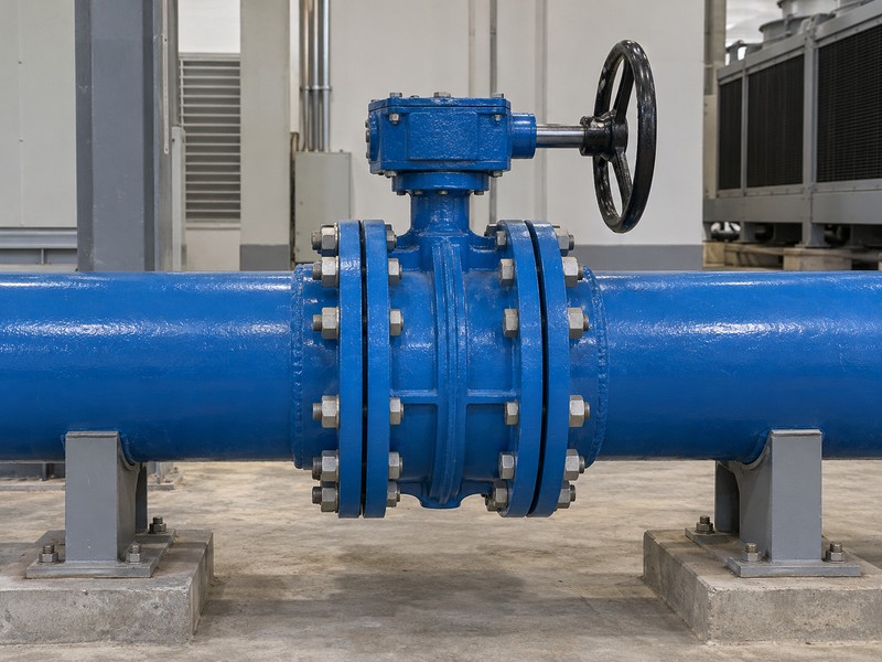
Can the same valve regulate flow?
Use a butterfly valve for modulation only when its supplier approves that model for the proposed operating range. Examine the installed flow characteristic, differential pressure, velocity, cavitation risk and actuator resolution. Adding a positioner changes how the drive positions the disc; it does not remove hydraulic limits or prove a specified control accuracy. In HVAC circulation, select the valve against the actual fluid, minimum flow and available pressure difference.
- Separate isolation duty from sustained throttling duty.
- Check solids, fibres and deposits that could obstruct the disc.
- Request application-specific approvals when the project requires them.
| Application | Potential fit | Reason for another review |
|---|---|---|
| Cooling-water isolation | Approved water configuration | Glycol, additives or unusual temperature |
| Chemical transfer | Reviewed lined assembly | Concentration, permeation or cleaning changes |
| Flow modulation | Model approved for control | Cavitation, noise or narrow controllable travel |
8. How do you check flange fit and open-disc clearance?
Check flange fit against the approved valve drawing and the actual pipe bore. The disc can extend outside the body's face-to-face length when it opens, so a matching bolt pattern alone is insufficient. Pipe lining, reducers, nearby equipment and a smaller internal diameter can obstruct the swept disc. Forcing the actuator through that interference can damage the seat, shaft or connected drive.
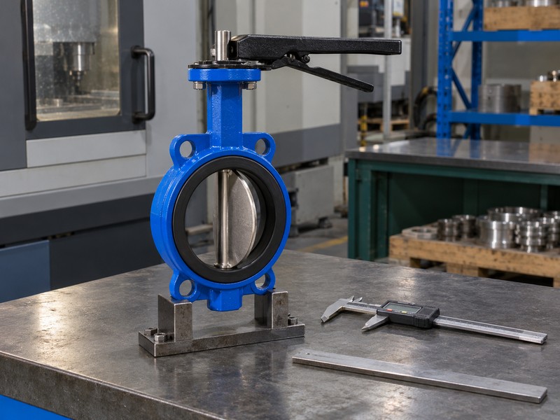
What should the installer verify before tightening?
Follow the valve's installation instructions for disc position, gasket use, alignment and bolt tightening. Some resilient seats also form the flange seal, while other constructions require a specified gasket arrangement. Do not add gaskets or sealant by habit. Support the pipe independently and check movement only under an approved isolated, depressurized procedure. The installer should record any interference or unusual resistance before attempting powered operation.
- Compare the mating bore with the complete swept-disc envelope.
- Use the approved gasket and tightening procedure.
- Check travel without forcing a misaligned assembly.
| Interface | Inspection | Possible consequence |
|---|---|---|
| Pipe bore | Disc clearance through full travel | Disc contact or stalled actuator |
| Flange faces | Alignment and approved seal arrangement | Uneven loading or leakage |
| Bolting | Length, engagement and tightening sequence | Damaged threads or compressed seat |
9. Which test records and documents should you request?
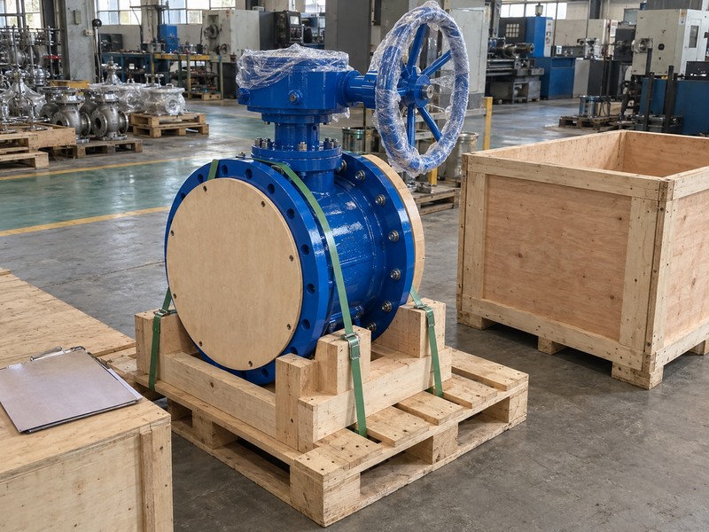
Request records that link the approved valve configuration to the items being supplied. A practical package includes the installation drawing, material list, pressure-temperature limits, operating-torque data and the agreed inspection results. Identify the test medium, pressure, direction, duration and acceptance criterion. A photograph of a pressure gauge cannot replace a traceable record of what the inspector tested and accepted.
How can you make the purchase order reviewable?
List the normal and limiting operating cases, required documents and unresolved deviations before approval. An EN 12266-1 or ISO 5208 leakage designation applies under the selected standard's test conditions; a Rate A result means no visible leakage during that specified test. It does not promise permanent leak-free service. To check a proposed configuration with RUITO, contact us with your medium, size, operating conditions and interface drawing so engineering can identify the required evidence.
- Link reports to product IDs and the approved drawing revision.
- Record directional and end-of-line limits in the purchase specification.
- Approve material or actuator changes before production release.
| Document | What to match | Decision it supports |
|---|---|---|
| Drawing and material list | Approved revision and supplied configuration | Interface and material acceptance |
| Rating and torque data | Actual pressure, temperature and direction | Service and drive selection |
| Inspection report | Product ID and agreed procedure | Release against stated acceptance criteria |
10. What questions do buyers ask about butterfly valves?
Q1. Can I use a butterfly valve as a check valve?
No. A normal butterfly valve needs a drive to position its disc and does not automatically prevent reverse flow. Select a dedicated check valve when the system needs automatic reverse-flow protection, and review its closing behavior with the piping system.
Q2. How do I know if a butterfly valve is fully open?
Verify the disc position and approved travel reference. A lever, gearbox pointer or limit switch can be incorrectly indexed after assembly or maintenance. The external indication should agree with actual movement through the commissioned travel range.
Q3. Can I remove downstream piping from a closed lug valve?
Only when that exact valve and installation have an approved end-of-line arrangement. Confirm size, temperature, differential pressure, bolt engagement, pipe restraint and the maintenance isolation procedure. Threaded lugs alone do not authorize the work.
Q4. What is the best seat for water containing glycol?
Use a compound approved for the complete mixture and temperature. State glycol type, concentration, inhibitor package and cleaning exposure. Review the finished valve's rating rather than relying on a general compatibility chart for unformulated rubber.
Q5. Can I order a replacement from its nominal size alone?
No. Nominal size leaves the connection, face-to-face length, disc clearance, seat, shaft interface and service rating unresolved. Supply the existing valve details and verified installation dimensions before approving an interchangeable replacement.