
Essential butterfly valve parts include the body, disk, stem, and seat, which work together to precisely control fluid flow. Picture your industrial facility facing sudden pipeline leaks that halt entire production lines. Every minute of unexpected downtime drains profits, and lacking clear knowledge of internal mechanisms only delays critical maintenance. By consulting a comprehensive butterfly valve parts diagram, you can rapidly identify failing components, replace them accurately, and restore your piping system to full operational health.
What Is a Butterfly Valve Parts Diagram?
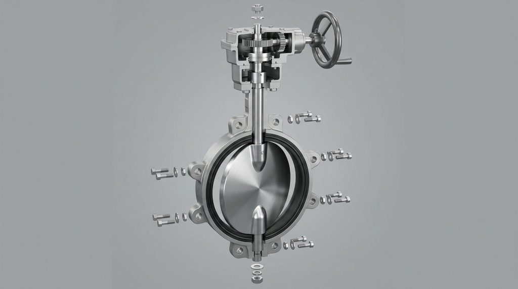
A butterfly valve parts diagram is a detailed visual schematic showing all internal and external components of the flow control device. You need this illustration to understand how each specific element interacts within the broader piping infrastructure.
Why Are Visual Schematics Important?
Here’s the deal: visual guides eliminate guesswork when you perform system maintenance or component upgrades. They allow technicians to disassemble and reassemble complex devices without damaging sensitive internal seals.
- They highlight correct assembly order
- They display exact locations of wear items
- They prevent mismatched component installations
How to Read the Schematic?
You should start by identifying the largest external structure and work your way inward to the central fluid control mechanisms.
The following breakdown illustrates the primary components you will find on most industrial drawings.
| Component Category | Function | Replacement Frequency |
|---|---|---|
| Outer Shell | Protects internal mechanics | Low |
| Control Center | Manages fluid passage | Medium |
| Sealing Rings | Prevents chemical leaks | High |
This table clarifies which mechanical sections require the most frequent monitoring and replacement.
Key Takeaway: Using a visual schematic empowers your maintenance team to perform faster, safer, and more accurate repairs.
Where Is the Body on a Butterfly Valve Parts Diagram?
The body appears as the large, robust outer casing holding all internal components together on a butterfly valve parts diagram. It serves as the primary structural anchor connecting the fluid control mechanism directly to your pipeline flanges.
What Are Wafer and Lug Styles?
What’s the real story? The two main structural designs determine how you will install the device into your piping network. Wafer designs slide between two flanges, while lug designs feature threaded inserts for dead-end services.
- Wafer styles save space and reduce weight
- Lug styles allow single-sided pipe removal
- Both designs withstand immense line pressure
How Does the Body Handle Pressure?
The rigid outer casing absorbs pipeline stress and keeps the internal moving parts perfectly aligned during high-pressure fluid transfers.
Review the structural pressure capacities associated with different casing designs.
| Body Design Type | Typical Application | Max Pressure Rating |
|---|---|---|
| Wafer Style | Continuous flow lines | 1000 kPa |
| Lug Style | Dead-end services | 520 kPa |
| Flanged Style | Heavy industrial mains | 1500 kPa |
This data demonstrates how structural casing choices directly influence your overall system pressure limits.
Key Takeaway: Selecting the correct casing style ensures your pipeline can safely handle expected mechanical stresses without rupturing.
Where Is the Disk on a Butterfly Valve Parts Diagram?
You will find the disk positioned precisely in the center of the fluid channel on a butterfly valve parts diagram. This rotating plate acts as the primary barrier that starts, stops, or throttles the flow of liquids.
How Does the Disk Control Flow?
This is where it gets interesting: the central plate rotates exactly ninety degrees to transition from fully closed to fully open. When positioned parallel to the liquid, it allows maximum throughput with minimal pressure drop.
- Zero-offset designs work for low pressures
- Double-offset designs reduce seal friction
- Triple-offset designs handle extreme temperatures
Why Does Disk Shape Matter?
The aerodynamic profile of the central plate minimizes fluid turbulence and prevents cavitation during high-speed chemical transfers.
Observe how different plate configurations perform under varying industrial conditions.
| Disk Offset Type | Friction Level | Ideal Operating Environment |
|---|---|---|
| Zero Offset | High | Clean water systems |
| Double Offset | Medium | Moderate chemical lines |
| Triple Offset | Minimal | High-pressure steam |
This comparison highlights how advanced plate geometries reduce mechanical wear and extend operational lifespans.
Key Takeaway: Upgrading to a specialized disk design can significantly reduce internal friction and improve fluid dynamics.
Where Is the Stem on a Butterfly Valve Parts Diagram?
The stem is depicted as a long vertical shaft connecting the external actuator to the internal disk on a butterfly valve parts diagram. It transmits the rotational force required to manipulate the fluid barrier against heavy line pressures.
What Are Common Shaft Designs?
You might be wondering: why do some devices use a single shaft while others use a split design? One-piece shafts offer superior strength, whereas two-piece setups maximize the flow area through the central pipe.
- One-piece stems resist high torque loads
- Two-piece stems increase fluid capacity
- Non-wetted stems avoid corrosive chemicals
How Does the Stem Avoid Damage?
Operators protect this critical rotating component by using specialized seals and resilient seating materials that block corrosive liquids.
Here is a summary of shaft configurations and their protective features.
| Shaft Configuration | Media Contact | Strength Profile |
|---|---|---|
| Wetted One-Piece | Direct contact | Extremely high |
| Non-Wetted Split | Isolated from fluid | Moderate |
| Splined Connection | Varies by design | Very high |
This chart illustrates the trade-offs between mechanical strength and chemical exposure for rotational shafts.
Key Takeaway: Choosing the right shaft configuration prevents premature mechanical failure and ensures smooth daily operation.
Where Is the Seat on a Butterfly Valve Parts Diagram?
The seat is located along the inner circumference of the main body housing on a butterfly valve parts diagram. It provides a flexible or rigid sealing surface that the disk compresses against to stop fluid movement.
What Materials Make the Best Seals?
Ready for the good part? Modern synthetic rubbers and advanced metals allow these seals to block everything from drinking water to aggressive acids. EPDM handles general water duties, while PTFE resists harsh organic solvents.
- EPDM excels in standard water applications
- NBR handles oil and petroleum effectively
- PTFE withstands highly corrosive chemicals
How Does Sealing Actually Work?
The rotating plate squeezes tightly against this inner ring, creating an impenetrable barrier that prevents microscopic leaks.
Consider the temperature and chemical limits of common sealing materials.
| Seat Material | Max Temperature | Best For |
|---|---|---|
| EPDM Rubber | 130°C | Municipal water |
| Nitrile (NBR) | 100°C | Oil pipelines |
| Solid Metal | 500°C+ | Superheated steam |
This data helps you match your sealing material to the exact thermal demands of your specific facility.
Key Takeaway: Installing the correct seating material is the most critical step in preventing hazardous chemical leaks.
Where Is the Drive on a Butterfly Valve Parts Diagram?
The drive, or actuator, sits at the very top of the assembly on a butterfly valve parts diagram. This external mechanism provides the mechanical, pneumatic, or electrical power needed to rotate the central shaft.
Which Actuation Method is Best?
Let’s dive deeper: manual levers work perfectly for small lines, but large industrial pipes require automated power to overcome fluid resistance. Pneumatic drives offer rapid response times, while electric motors provide precise positional control.
- Manual levers suit small, accessible pipes
- Pneumatic drives deliver fast, reliable power
- Electric motors integrate with digital networks
How Does Automation Improve Safety?
Automated drives remove human operators from hazardous areas and can instantly shut down pipelines during an emergency.
Explore the operational differences between common drive systems.
| Drive Type | Speed | Primary Advantage |
|---|---|---|
| Manual Gearbox | Slow | Requires no power |
| Pneumatic | Very Fast | Failsafe capabilities |
| Electric Motor | Moderate | High precision |
This table shows why different drive methods are chosen based on speed and safety requirements.
Key Takeaway: Automating your fluid control systems enhances both worker safety and overall process efficiency.
How Do Temps Affect a Butterfly Valve Parts Diagram?
Extreme temperatures dictate the specific metallic and synthetic materials required in a butterfly valve parts diagram. High heat demands specialized alloys, while freezing conditions require materials that resist catastrophic brittle fractures.
How Does Extreme Heat Alter Parts?
Here is the truth: standard rubber components melt and fail rapidly when exposed to superheated steam or thermal oils. Facilities must transition to Inconel or Stellite components to maintain integrity above five hundred degrees Celsius.
- Standard rubber fails at high temperatures
- Metal-to-metal seals handle extreme heat
- Graphite packing prevents hot gas leaks
What About Freezing Environments?
Cryogenic applications require extended bonnets to keep the external actuator from freezing solid.
Review the thermal capabilities of various industrial setups.
| Temperature Range | Required Material | Typical Industry |
|---|---|---|
| Cryogenic | Austenitic Stainless | LNG processing |
| Ambient | Ductile Iron | Water treatment |
| Extreme Heat | Inconel / Stellite | Power generation |
This thermal breakdown proves that operating environments strictly dictate your mechanical hardware choices.
Key Takeaway: Matching your hardware to your thermal environment prevents sudden material degradation and catastrophic failure.
What Materials Suit a Butterfly Valve Parts Diagram?
Material selection defines the durability and chemical resistance of every component shown on a butterfly valve parts diagram. Industrial operators choose specific alloys and plastics based entirely on the aggressiveness of the media they process.
Why Choose Stainless Steel?
Consider this fact: stainless steel contains molybdenum, which actively fights off pitting and corrosion in harsh chemical environments. Ductile iron provides a cost-effective alternative for clean, non-corrosive municipal water applications.
- Ductile iron is perfect for standard water
- Stainless steel resists severe chemical attack
- Aluminum bronze prevents salt water decay
Can Plastics Replace Metal Parts?
High-grade plastics offer incredible resistance to acidic solutions where traditional metals would quickly dissolve.
Here is a material guide for various challenging fluid types.
| Fluid Media | Recommended Material | Benefit |
|---|---|---|
| Salt Water | Aluminum Bronze | Stops marine corrosion |
| Strong Acids | UPVC / PVDF | Chemical immunity |
| Clean Water | Coated Ductile Iron | Highly cost-effective |
This material matrix ensures you deploy the most resilient and economical metals for your specific fluid.
Key Takeaway: Selecting the proper base material dramatically extends equipment lifespan and reduces lifetime maintenance costs.
How Does Size Impact a Butterfly Valve Parts Diagram?
The physical dimensions of your pipeline drastically alter the engineering requirements illustrated in a butterfly valve parts diagram. Massive pipe diameters demand heavy-duty structural reinforcements and powerful motorized drives to function safely.
Why Are These Devices Space Savers?
Truth be told: these quarter-turn devices are incredibly narrow, making them the ultimate choice for cramped, high-density piping networks. They weigh significantly less than bulky gate alternatives, reducing structural stress on your pipes.
- Narrow profiles fit into incredibly tight spaces
- Lighter weight reduces the need for pipe supports
- Compact designs lower shipping and handling costs
How Do Massive Sizes Operate?
When pipe diameters exceed twelve inches, manual operation becomes impossible due to immense fluid pressure against the central plate.
Observe how physical dimensions change operational requirements.
| Pipe Diameter | Weight Profile | Actuation Required |
|---|---|---|
| 2 to 6 inches | Very Light | Manual Lever |
| 8 to 14 inches | Moderate | Manual Gearbox |
| 16+ inches | Very Heavy | Powered Actuator |
This size guide illustrates why large-scale fluid systems completely depend on heavy-duty mechanical assistance.
Key Takeaway: Taking advantage of this compact design allows you to engineer tighter, more efficient industrial piping layouts.
How to Fix Parts via a Butterfly Valve Parts Diagram?
Maintenance technicians use a butterfly valve parts diagram to safely disassemble, inspect, and repair failing components. Regular inspection of wear points prevents minor internal leaks from escalating into major environmental hazards.
What Are Common Failure Points?
But here’s the kicker: the synthetic rubber seating ring is almost always the first part to degrade or tear. A worn seal allows fluid to bypass the central plate, causing noticeable pressure drops across your network.
- Rubber seats tear under abrasive conditions
- Shaft packing leaks from overtightening
- Actuators jam due to poor lubrication
How Do You Replace the Seal?
You must completely depressurize the line and remove the outer hardware before attempting to extract the damaged rubber ring.
Review the most effective maintenance actions for common issues.
| Symptom | Probable Cause | Action Required |
|---|---|---|
| Shaft Leak | Worn V-packing | Replace packing rings |
| Internal Leak | Torn rubber seat | Install new seat |
| Stiff Operation | Dry actuator gears | Apply fresh grease |
This troubleshooting guide helps you quickly diagnose symptoms and apply the correct mechanical fixes.
Key Takeaway: Proactive maintenance and timely seal replacements drastically reduce the risk of expensive unplanned outages.
How Can Optimal Valve Setup Elevate Your Operations?
Mastering the mechanics behind these critical devices allows you to build safer, more resilient, and highly efficient industrial networks. By identifying structural weaknesses and selecting the perfect materials for your specific environment, you eliminate the hidden risks that cause sudden pipeline failures. We specialize in providing engineered flow control technologies that directly address your most demanding pressure and temperature challenges.
When you partner with reliable manufacturing experts, you gain access to robust hardware designed specifically to keep your operations running smoothly. Our commitment is to deliver unwavering quality that protects your infrastructure and maximizes your operational uptime. If you are ready to secure your piping systems against unexpected failures, contact us today to discuss your custom flow control requirements.
FAQs
Q1: What are the main components of a butterfly valve?
The main components are the body, disk, stem, and seat. The body provides structure, the disk manages flow, the stem transfers power, and the seat guarantees a tight seal.
Q2: How do these devices compare to other valve types’ space requirements?
They are significantly more compact and lightweight than traditional options. This narrow profile makes them perfect for facilities with severe space and weight restrictions.
Q3: What types of actuators are commonly used with these devices?
Common options include manual levers, pneumatic cylinders, and electric motors. Operators choose the drive based on required speed, pipe size, and facility automation levels.
Q4: How often should the internal components be maintained?
Maintenance frequency depends entirely on your fluid media and pressure levels. Abrasive chemicals require frequent checks, while clean water systems can operate for years without intervention.
Q5: What are the temperature and pressure capabilities of these devices?
High-performance models can handle up to 500°C and 51 bar of pressure. Standard rubber-lined models are typically limited to ambient temperatures and much lower pressure environments.