

Determining whether your valve is open or closed relies primarily on checking visual indicators like the toothed disc, external arrows, or electronic feedback signals. Picture a typical scenario where you are managing a complex piping system and suddenly lose track of valve statuses during a high-pressure shift. A misaligned disc quickly leads to unexpected flow restrictions, causing severe pressure buildup and system damage. Fortunately, identifying the precise butterfly valve open position offers an easy way to avoid these operational hazards. Relying on accurate visual markers and electronic sensors gives you full control over fluid regulation.
How does a toothed disc reveal the butterfly valve open position?
Observing the toothed disc gives you a direct visual confirmation of the butterfly valve open position, typically showing 10 distinct scale markings. Checking this specific butterfly valve open position prevents sudden flow disruptions in your pipeline. The first notch on this scale always represents a fully closed state, stopping fluid entirely. When the handle aligns with the last notch, the disc sits parallel to the flow direction, confirming an unobstructed channel.
What are the mechanical benefits of this visual scale?
This straightforward design helps operators quickly adjust fluid flow without complex tools. You just look at the scale and know the current status. Here is the deal, relying on a mechanical scale reduces the chances of electronic sensor failures in harsh environments.
- Provides immediate visual confirmation.
- Requires zero power to operate.
- Reduces maintenance downtime.
Key Takeaway: Mechanical toothed discs offer a reliable, fail-proof method for verifying valve orientation without external power.
| Feature | Closed State | Open State |
|---|---|---|
| Disc Angle | 90 degrees | 0 degrees |
| Fluid Flow | Blocked | Unobstructed |
| Notch Position | First notch | Last notch |
This table highlights how the mechanical scale directly corresponds to fluid restriction levels.
What role do position indicators play in valve status?
Position indicators use external arrows and clear markings to show the butterfly valve open position at a glance. Verifying the butterfly valve open position through these indicators ensures that your system maintains optimal flow rates. Many valves feature a prominent arrow fixed directly onto the turbine head. This arrow aligns with specific raised or painted markings on the valve body itself.
How do external arrows improve operator accuracy?
Clear external markings eliminate the guesswork during routine inspections. You can simply walk past the installation and verify the alignment. You might be wondering, do these indicators wear off over time? Manufacturers typically cast or deeply engrave these marks to withstand harsh industrial conditions.
- Enables rapid visual inspections.
- Reduces operator errors during shifts.
- Withstands severe environmental wear.
Key Takeaway: External arrows provide a durable, intuitive method for operators to check fluid channels from a distance.
| Indicator Type | Visibility | Durability |
|---|---|---|
| Painted Arrow | Moderate | Low |
| Cast Marking | High | High |
| Engraved Scale | High | High |
Comparing these indicator types shows that cast markings offer the best long-term reliability in industrial settings.
How do feedback signals confirm the butterfly valve open position?
Electronic feedback signals transmit real-time data to control rooms to confirm the precise butterfly valve open position. Tracking the butterfly valve open position electronically gives operators instant alerts if a malfunction occurs. Sensors integrated directly into the valve mechanism detect the exact rotational angle of the disc. These sensors convert mechanical movement into readable electrical data for your supervisory systems.
Can limit switches enhance system automation?
Integrating electronic feedback allows your facility to automate complex fluid control sequences. You no longer need manual spot checks for every single valve. Ready for the good part? These signals instantly trigger alarms if the disc fails to reach its intended destination.
- Provides continuous remote monitoring.
- Enables automated emergency shutdowns.
- Logs historical performance data.
Key Takeaway: Electronic feedback bridges the gap between mechanical hardware and modern automated control systems.
| Signal Type | Application | Accuracy |
|---|---|---|
| Mechanical Switch | Basic On/Off | Moderate |
| Proximity Sensor | Non-contact | High |
| Continuous Transmitter | Throttling | Very High |
Selecting the right signal type depends heavily on whether you need basic monitoring or precise flow regulation.
Can remote monitoring verify the butterfly valve open position?
Remote monitoring systems use digital dashboards to display the exact butterfly valve open position across your entire plant. Monitoring the butterfly valve open position from a central hub allows you to supervise multiple pipelines simultaneously. Modern industrial installations connect individual valve sensors to a centralized programmable logic controller. This setup eliminates the need for operators to physically access dangerous or confined spaces.
How do digital dashboards change daily operations?
Centralized control screens provide a comprehensive overview of your fluid network. You can spot anomalies before they escalate into major leaks. This is where it gets interesting, predictive maintenance algorithms can analyze this remote data to forecast hardware failures.
- Centralizes all operational data.
- Keeps personnel out of hazardous zones.
- Facilitates rapid emergency responses.
Key Takeaway: Centralized digital monitoring vastly improves plant safety and operational oversight.
| Monitoring System | Range | Data Speed |
|---|---|---|
| Local Panel | < 100 meters | Instant |
| Plant SCADA | Facility-wide | < 1 second |
| Cloud Dashboard | Global | 1-2 seconds |
Upgrading to a facility-wide SCADA system offers the best balance of speed and comprehensive oversight.
How does handle orientation reveal the butterfly valve open position?
The physical direction of the operating handle directly indicates the butterfly valve open position by aligning with the pipe. Aligning the handle correctly ensures the butterfly valve open position matches your intended flow parameters. When the handle sits parallel to the pipeline, the internal disc is fully open. Conversely, a handle positioned perpendicular to the pipe signifies a completely closed fluid channel.
Why is handle alignment so intuitive?
This geometric relationship mirrors the actual internal flow path, making it extremely easy to understand. You do not need specialized training to interpret this mechanical setup. Let’s look at the facts, standardized handle orientations prevent catastrophic miscommunications between different shift teams.
- Matches internal disc orientation exactly.
- Requires no external power source.
- Functions as a universal visual standard.
Key Takeaway: Parallel and perpendicular handle alignments offer the most universal and immediate status recognition.
| Handle Orientation | Disc Status | Flow Status |
|---|---|---|
| Parallel | Open | Unobstructed |
| 45 Degrees | Partially Open | Throttled |
| Perpendicular | Closed | Blocked |
This orientation standard remains consistent across almost all manual quarter-turn fluid control devices.
Why confirm the precise butterfly valve open position during operation?
Knowing the precise butterfly valve open position prevents fluid leaks, pressure spikes, and catastrophic pipeline failures. Failing to verify the butterfly valve open position can cause severe damage to expensive downstream pumps. A partially closed disc creates unexpected turbulence and cavitation within the fluid stream. These mechanical stresses rapidly degrade internal seals and shorten the lifespan of the entire installation.
What are the risks of incorrect positioning?
Operating a pipeline with misaligned discs leads to rapid mechanical degradation. You might experience sudden vibration issues that loosen flange connections. Consider this, repairing a blown pipe seal costs significantly more than routine status verification.
- Prevents damaging cavitation.
- Reduces excessive vibration.
- Protects downstream equipment.
Key Takeaway: Strict position verification acts as the primary defense against unexpected pipeline deterioration.
| Operational Risk | Cause | Consequence |
|---|---|---|
| Cavitation | Partial throttling | Pitted disc |
| Vibration | Uneven flow | Loose flanges |
| Water Hammer | Sudden closure | Pipe rupture |
Addressing these risks early through proper alignment saves facilities from costly emergency repairs.
How does disc movement impact the butterfly valve open position?
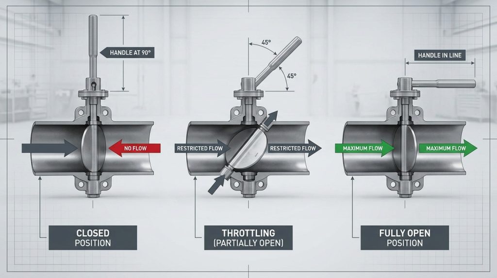
The internal disc rotates exactly 90 degrees to achieve the full butterfly valve open position. Understanding how this 90-degree rotation affects the butterfly valve open position helps you calibrate actuators accurately. Unlike rising stem gate valves that move up and down, this quarter-turn motion keeps the disc within the fluid path. The fluid simply flows around the streamlined metal plate when fully opened.
How does this differ from gate valves?
Gate valves require multiple handle rotations to lift the internal barrier completely out of the way. You can operate a quarter-turn mechanism much faster during sudden emergencies. Truth be told, this specific rotational movement requires significantly less vertical installation space.
- Operates via 90-degree rotation.
- Remains inside the fluid stream.
- Actuates much faster than gate types.
Key Takeaway: The quarter-turn rotational design provides rapid actuation while consuming minimal physical space.
| Valve Type | Movement | Actuation Speed |
|---|---|---|
| Butterfly | Quarter-turn | Very Fast |
| Gate | Linear lift | Slow |
| Globe | Linear lift | Slow |
Comparing actuation speeds demonstrates why rotational designs dominate emergency shutoff applications.
What happens to fluid flow at the maximum open state?
Fluid passes cleanly around the parallel disc when it reaches the maximum open state. Confirming this specific butterfly valve open position guarantees that your pumps operate at maximum efficiency. The streamlined profile of the central plate minimizes resistance and prevents pressure drops across the connection. Maintaining this optimal flow path reduces energy consumption for your industrial pumps.
Does the disc cause permanent flow restriction?
Even when fully opened, the disc profile remains directly in the center of the pipe. You will always experience a minor pressure drop compared to a completely hollow pipe. The best part? Modern engineered discs feature aerodynamic contours that make this restriction practically negligible.
- Fluid splits around the central plate.
- Aerodynamic contours reduce drag.
- Pumps consume less energy.
Key Takeaway: Streamlined internal components ensure maximum fluid transfer efficiency despite remaining in the flow path.
| Disc Design | Pressure Drop | Flow Efficiency |
|---|---|---|
| Flat Plate | Moderate | Fair |
| Streamlined | Low | High |
| Offset Double | Very Low | Excellent |
Investing in streamlined or offset disc designs drastically improves long-term pumping efficiency.
Can switches detect the butterfly valve open position automatically?
Limit switches attach directly to the actuator shaft to detect the exact butterfly valve open position automatically. Installing these switches to track the butterfly valve open position provides reliable data for your programmable controllers. As the internal shaft rotates, physical cams trigger the microswitches at specific pre-set angles. These triggers instantly send open or closed confirmation signals to the main control panel.
Are these switches difficult to calibrate?
Setting up limit switches requires simple mechanical adjustments during the initial installation phase. You loosen the cam set screws and rotate them until they click at the correct angle. Here is the kicker, once properly locked down, these mechanical triggers maintain their calibration for years.
- Triggers at specific rotation angles.
- Provides reliable binary signals.
- Maintains calibration long-term.
Key Takeaway: Mechanical limit switches offer a highly durable and simple method for automating position detection.
| Component | Function | Adjustability |
|---|---|---|
| Microswitch | Sends signal | Fixed |
| Trigger Cam | Hits switch | High |
| Shaft | Rotates cam | N/A |
Properly aligning the trigger cams ensures the control room receives perfectly timed status updates.
How do maintenance checks verify position reading accuracy?
Regular maintenance ensures that external indicators accurately reflect the true internal state. Validating the butterfly valve open position during routine checks prevents false readings that cause operational errors. Technicians physically inspect the linkages between the actuator shaft and the visual pointer. They tighten any loose connections to guarantee the arrow moves perfectly in sync with the internal disc.
What happens if indicators become misaligned?
A loose indicator might point to the open setting while the internal disc remains totally closed. You risk starting high-pressure pumps against a dead end, causing severe damage. Think about it, spending ten minutes checking a set screw prevents thousands of dollars in ruined equipment.
- Ensures indicators match internal state.
- Prevents catastrophic pump failures.
- Extends hardware lifespan.
Key Takeaway: Routine visual and mechanical verification protects your facility from false readings and subsequent equipment damage.
| Maintenance Task | Frequency | Purpose |
|---|---|---|
| Check set screws | Monthly | Prevent slipping |
| Clean scale | Quarterly | Maintain visibility |
| Test switch | Bi-annually | Ensure signaling |
Adhering to this basic maintenance schedule guarantees your position indicators remain trustworthy year-round.
Securing Your Fluid Control Systems Today
Consistent operational success requires reliable components and accurate status tracking. This guide resolved common confusion regarding visual indicators, electronic feedback, and mechanical alignment for your pipeline hardware. We provide precision-engineered fluid solutions that eliminate system failures and keep your processes running smoothly. For industrial-grade reliability that protects your bottom line, please contact us today to discuss your specific engineering needs. RUITO stands as your dependable partner in achieving zero-defect fluid management worldwide.
FAQ
Q1: Can I check the valve status without external power?
Yes, you can rely entirely on mechanical indicators like the toothed disc or handle orientation. These physical markers move directly with the internal shaft, requiring absolutely zero electricity to display the current state.
Q2: What’s the best way to monitor valves in a hazardous area?
Remote monitoring via electronic feedback signals offers the safest solution. Sensors transmit real-time rotational data directly to your centralized control room, keeping your personnel far away from dangerous environments.
Q3: How do I know if the external arrow is accurate?
You must perform regular physical maintenance checks to verify the arrow’s alignment. Inspecting and tightening the set screws connecting the indicator to the actuator shaft ensures the reading matches the internal disc.
Q4: Can I use a butterfly design for precise flow throttling?
Yes, but you should utilize a continuously transmitting position sensor rather than basic limit switches. This setup provides the exact degree of rotation, allowing your automated systems to regulate fluid volumes accurately.
Q5: What’s the best indicator for quick visual inspections?
A standardized handle orientation provides the fastest and most universally understood visual cue. When the handle runs parallel to the pipe, the channel is free; when perpendicular, the fluid path is completely blocked.