
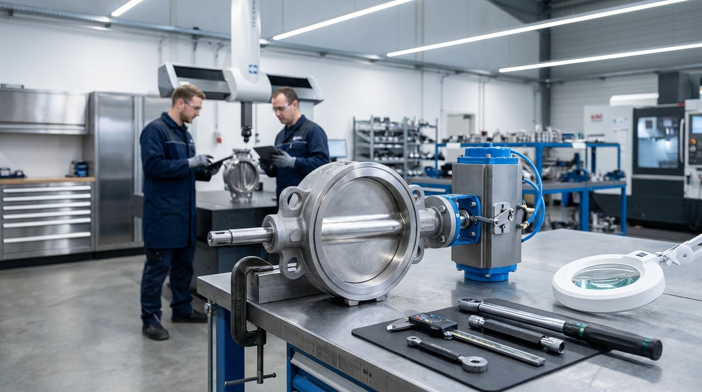
Plant operators frequently struggle with unexpected pipeline leaks that cause costly system downtime. The frustration mounts when a newly installed system fails pressure tests simply because of improper internal component alignment. Implementing a meticulously controlled butterfly valve assembly process is your reliable solution to guarantee zero-leakage performance and long-term mechanical stability.
Why is the butterfly valve assembly process critical for reliable performance?
The butterfly valve assembly process determines the exact mechanical alignment and sealing integrity required to prevent catastrophic pipeline failures. A proper butterfly valve assembly ensures that internal components function seamlessly under extreme operational pressures. When technicians ignore strict assembly tolerances, the resulting friction destroys the sealing rings prematurely. You must prioritize precision during this stage to maximize the operational lifespan of your fluid control systems.
Manufacturers rely on this rigorous procedure to eliminate hidden defects before products reach the field. Skipping steps during construction inevitably leads to inconsistent torque requirements and severe media leakage. Properly executed workflows guarantee that every unit performs safely in demanding industrial environments.
What happens when assembly tolerances are ignored?
Here’s the deal: ignoring precise measurements during construction causes immediate structural imbalances within the casing. Components that fit too tightly will experience rapid wear, while loose fittings allow fluid to escape.
You can prevent these issues by following standard guidelines:
- Measure component clearances using calibrated instruments.
- Apply uniform torque to all fastening bolts.
- Verify stem alignment prior to final securing.
Key Takeaway: Strict adherence to alignment protocols prevents premature mechanical failure and ensures long-term operational safety.
| Consequence | Primary Cause | Operational Impact |
|---|---|---|
| Premature Wear | Excessive friction | Reduced component lifespan |
| Fluid Leakage | Loose tolerances | System pressure loss |
| High Torque | Misaligned stem | Actuator failure |
The data highlights how improper tolerances directly cause severe mechanical and operational failures.
What are the core components required for a proper butterfly valve assembly?
The core components required for a successful butterfly valve assembly include the body, disc, stem, elastic seat, and actuator mechanism. Every butterfly valve assembly relies on these specific parts working in perfect unison to regulate media flow. The disc acts as the primary shut-off barrier, while the stem transfers rotational force from the operator. You must verify that all parts meet exact material specifications before beginning the construction phase.
Using substandard materials drastically reduces the effectiveness of the entire unit. Engineers carefully select specific alloys and elastomers based on the intended service environment. Identifying each piece correctly ensures a smooth and error-free integration process.
How do component materials affect overall quality?
You might be wondering: why do specific applications require vastly different seating materials? High-temperature environments demand resilient metal alloys, whereas standard water systems utilize flexible rubber elastomers.
Consider these critical component categories:
- Pressure-bearing shells forged from ductile iron or steel.
- Rotational shafts crafted from corrosion-resistant stainless alloys.
- Flexible sealing rings formulated from synthetic rubber or PTFE.
Key Takeaway: Selecting the correct materials for individual components is fundamental to achieving optimal fluid regulation and longevity.
| Component | Function | Common Material |
|---|---|---|
| Body | Pressure containment | Ductile Iron |
| Disc | Flow regulation | Stainless Steel |
| Seat | Leak prevention | EPDM / PTFE |
This breakdown illustrates the specific functional purpose and typical material for each critical valve part.
How do you prepare and clean the body for butterfly valve assembly?
You prepare the body for a butterfly valve assembly by thoroughly removing all dirt, grease, and metallic shavings from the internal cavity. Proper preparation during butterfly valve assembly prevents debris from damaging the delicate sealing surfaces later on. Technicians use specialized industrial solvents and lint-free cloths to achieve a pristine internal environment. You must visually inspect every threaded hole and flange face for hidden contaminants before proceeding.
Even microscopic particles can compromise the structural integrity of the final product. A clean environment ensures that lubricants apply evenly and components slide together without scratching. Taking time to sanitize the workspace directly correlates with higher passing rates during final testing.
Why is visual inspection crucial before construction?
What’s the real story? Skipping the initial visual check often results in costly rework after the unit fails its pressure test. Identifying casting defects early saves significant time and manufacturing resources.
Always perform these preparation tasks:
- Scrub internal cavities with approved industrial solvents.
- Blow out threaded holes using compressed air.
- Examine flange faces for uneven textures or deep scratches.
Key Takeaway: Meticulous cleaning and inspection routines eliminate abrasive particles that threaten sealing integrity.
| Preparation Step | Tool Used | Objective |
|---|---|---|
| Debris Removal | Compressed air | Clear threaded holes |
| Surface Cleaning | Lint-free cloth | Remove residual grease |
| Defect Check | Visual inspection | Identify casting flaws |
Systematic preparation significantly reduces the risk of internal contamination and subsequent mechanical damage.
What is the correct method for installing the seat during butterfly valve assembly?
The correct method involves evenly pressing the elastomer into the body groove to prevent twisting during the butterfly valve assembly. Executing this step of the butterfly valve assembly flawlessly guarantees a tight seal against the internal disc. You can apply a thin layer of compatible silicone grease to facilitate a smoother insertion. It is imperative to verify that the elastomer sits completely flush against the metallic retaining walls.
Uneven seating causes uneven pressure distribution, leading to rapid material degradation. Operators must carefully manipulate the rubber element without using sharp tools that might puncture the surface. Perfect alignment here is non-negotiable for achieving zero-leakage performance.
How do you prevent elastomer twisting?
Ready for the good part? You can easily avoid twisting by applying gentle, uniform pressure around the entire circumference of the ring. Forcing the material into place unevenly creates localized stress points that fail under load.
Follow these installation guidelines:
- Apply appropriate lubrication to the outer edge.
- Press the material evenly starting from opposite sides.
- Inspect the inner contour for any visible distortion.
Key Takeaway: Installing the seating ring evenly prevents structural deformities and ensures a perfect, watertight seal.
| Defect Type | Cause | Solution |
|---|---|---|
| Twisting | Uneven insertion pressure | Apply uniform force |
| Tearing | Use of sharp tools | Use blunt pressing aids |
| Bulging | Incorrect sizing | Verify part dimensions |
Avoiding these common installation defects guarantees the structural integrity of the internal sealing mechanism.
How should you align the disc and stem in a butterfly valve assembly?
You must insert the stem precisely through the central shaft hole of the disc during the butterfly valve assembly. This critical phase of butterfly valve assembly dictates how smoothly the unit will operate under pressure. The flat keyway section of the shaft needs to match the corresponding slot on the plate perfectly. You should angle the combined unit slightly to slide it safely into the prepared casing.
Forcing the pieces together often results in severely damaged bearing surfaces. The rotational element must pivot freely within the cavity without scraping against the metallic walls. Proper alignment minimizes operational friction and extends the lifespan of the actuator mechanism.
What are the signs of improper shaft insertion?
This is where it gets interesting… if the rotational shaft binds during manual rotation, the internal geometry is definitely misaligned. You will immediately notice uneven resistance when attempting to turn the mechanism by hand.
Check for these alignment indicators:
- Smooth rotation from zero to ninety degrees.
- Equal clearance gaps on all sides of the plate.
- Absence of grinding noises during manual operation.
Key Takeaway: Flawless geometric alignment between the rotational elements minimizes friction and prevents catastrophic operational failures.
| Alignment Check | Desired Outcome | Failure Symptom |
|---|---|---|
| Manual Rotation | Smooth movement | Binding or sticking |
| Gap Measurement | Uniform clearance | Uneven spacing |
| Acoustic Check | Silent operation | Grinding sounds |
Verifying these alignment metrics ensures the internal mechanism operates with maximum efficiency and minimal wear.
Why is bearing and gland positioning crucial in butterfly valve assembly?
Accurate bearing and gland positioning stabilizes the rotational shaft within the butterfly valve assembly to prevent side-loading. Any deviation during the butterfly valve assembly process causes the shaft to wobble and destroy the packing material. You press the bearings into the upper and lower seats to absorb the immense torque generated by the actuator. Tightening the gland bolts evenly maintains the exact compression needed for the O-rings to function correctly.
Over-tightening these bolts drastically increases the physical effort required to operate the device. Conversely, under-tightening the hardware allows high-pressure fluids to escape along the vertical shaft. Striking the perfect balance ensures optimal functionality and prevents dangerous external emissions.
How do you achieve optimal gland compression?
But here’s the kicker… applying torque sequentially in a cross-pattern guarantees that the compression plate lowers perfectly flat. Rushing this step and tightening one side completely will permanently warp the internal packing material.
Follow these compression best practices:
- Insert bearings squarely into their designated housings.
- Tighten retaining bolts gradually using a crisscross sequence.
- Verify the final torque values using a calibrated wrench.
Key Takeaway: Correctly positioning and securing the structural supports prevents shaft instability and eliminates dangerous external leaks.
| Component | Function | Assembly Criticality |
|---|---|---|
| Bearings | Support shaft rotation | Prevents side-loading |
| Gland Plate | Compress packing | Seals external leaks |
| O-rings | Block fluid escape | Requires even pressure |
Proper installation of these supporting elements directly dictates the external sealing reliability of the unit.
How do you correctly install the operator in a butterfly valve assembly?
You correctly install the operator by aligning its output socket exactly with the square head of the butterfly valve assembly. Securing the driving mechanism properly in a butterfly valve assembly allows for accurate manual or automated fluid control. You must insert the retaining clips firmly to ensure the handle does not detach during rigorous operation. It is vital to confirm that the handle’s physical orientation matches the internal plate’s position perfectly.
A misaligned handle provides false visual feedback to the plant operators managing the pipeline. When the lever sits parallel to the pipe, the internal passage must be entirely open. Accurate synchronization between the exterior controls and interior mechanics prevents dangerous operational errors.
Why does visual orientation matter for operators?
Picture this: an operator assumes the pipeline is closed based on handle position, but fluid is still rushing through. This dangerous scenario occurs solely due to improper synchronization during the final construction phase.
Ensure correct operator installation by:
- Matching the gear slot to the shaft keyway perfectly.
- Securing all mounting brackets with specified hardware.
- Testing the open and closed visual indicators for accuracy.
Key Takeaway: Precise synchronization between the external handle and the internal plate ensures safe and accurate pipeline management.
| Indicator Position | Valve Status | Expected Flow |
|---|---|---|
| Parallel to pipe | Fully Open | Maximum capacity |
| Perpendicular | Fully Closed | Zero flow |
| 45-degree angle | Throttling | Partial flow |
Accurate visual indicators are essential for operators to safely manage fluid dynamics within the system.
What initial tests are required after completing a butterfly valve assembly?
You must perform a manual rotation check and a preliminary pneumatic leak test after finishing the butterfly valve assembly. These initial evaluations validate the fundamental integrity of your butterfly valve assembly before it moves to high-pressure testing. You rotate the mechanism fully to ensure no internal parts grind against each other awkwardly. Applying soapy water to the exterior joints while injecting low-pressure air quickly reveals any glaring construction flaws.
Discovering a minor defect at this stage saves immense resources compared to failing a rigorous hydrostatic evaluation. Technicians monitor the pressure gauges closely to detect even the slightest pressure drop. Passing these initial hurdles proves that the basic mechanical structure is sound.
How do you conduct a pneumatic leak test?
You might be wondering: why use air instead of water for the very first diagnostic check? Air molecules are significantly smaller than water molecules, making them perfect for exposing microscopic sealing imperfections quickly.
Execute the initial tests by:
- Cycling the mechanism manually from zero to ninety degrees.
- Injecting low-pressure compressed air into one side.
- Coating external joints with a specialized leak-detection fluid.
Key Takeaway: Conducting preliminary pneumatic evaluations efficiently identifies structural flaws before subjecting the unit to extreme hydrostatic pressures.
| Test Type | Medium Used | Primary Objective |
|---|---|---|
| Rotation | Manual force | Verify smooth operation |
| Pneumatic | Compressed air | Detect microscopic leaks |
| Visual | Observation | Confirm structural integrity |
These foundational tests provide immediate feedback regarding the mechanical success of the construction process.
How can you troubleshoot common problems during butterfly valve assembly?
You troubleshoot problems by systematically checking component alignment and torque specifications during the butterfly valve assembly. When a butterfly valve assembly fails a diagnostic check, you must dismantle the affected area to locate the root cause. If the rotational shaft feels stiff, you should immediately loosen the gland bolts and realign the internal geometries. Addressing external leaks usually requires replacing damaged O-rings or applying more uniform compression to the packing.
Ignoring minor issues during the diagnostic phase guarantees major malfunctions once the unit enters active service. Technicians must document every anomaly they encounter to improve future manufacturing procedures. Identifying and rectifying these errors promptly maintains high production standards.
What causes a valve to fail the seal test?
What’s the real story? A failed seal test almost always stems from a twisted elastomer ring or a deeply scratched rotational plate. You cannot achieve a perfect vacuum if the contact surfaces contain microscopic abrasions or structural deformities.
Troubleshoot common defects by:
- Inspecting the rubber element for unintended twisting or tearing.
- Examining the metallic plate for debris or surface scratches.
- Adjusting the actuator torque to ensure complete closure.
Key Takeaway: Systematic troubleshooting and rapid component replacement isolate and resolve mechanical defects before deployment.
| Symptom | Probable Cause | Corrective Action |
|---|---|---|
| Stiff rotation | Misaligned stem | Realign internal components |
| Internal leak | Damaged seat | Replace elastomer ring |
| External leak | Loose gland | Retighten packing bolts |
Correctly identifying the root cause allows technicians to implement the exact mechanical fix required.
What quality control standards govern a successful butterfly valve assembly?
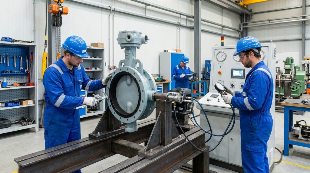
Rigorous hydrostatic testing and precise dimensional inspections govern the ultimate success of your butterfly valve assembly. A certified butterfly valve assembly must meet internationally recognized standards for pressure retention and operational torque. You subject the closed unit to water pressure significantly higher than its intended operating capacity to guarantee safety. Inspectors carefully measure flange dimensions and bolt-hole spacing to ensure seamless integration into existing pipelines.
Meeting these rigorous benchmarks proves that the manufacturing process was executed flawlessly from start to finish. Detailed documentation accompanies every approved unit to provide traceability for plant engineers. Maintaining strict quality control safeguards your facility against unexpected equipment failures.
Why is hydrostatic testing mandatory?
Here’s the deal: hydrostatic testing forces the unit to endure conditions far worse than it will ever experience in reality. This extreme evaluation proves beyond a doubt that the structural shell and internal seals can handle catastrophic pressure spikes.
Ensure quality control by:
- Pressurizing the unit to 1.5 times its rated capacity.
- Measuring operating torque with calibrated digital tools.
- Verifying physical dimensions against engineering blueprints.
Key takeaway: Adhering to strict international testing standards guarantees the reliability and safety of the final industrial product.
| Standard Check | Testing Method | Acceptance Criteria |
|---|---|---|
| Shell Strength | Hydrostatic pressure | No visible rupture |
| Seat Integrity | High-pressure water | Zero fluid leakage |
| Dimensions | Caliper measurement | Matches exact blueprints |
These stringent quality control metrics ensure that every unit performs flawlessly in demanding industrial environments.
Shaping the Future of Valve Engineering
The intricate process of constructing reliable fluid control mechanisms requires unwavering attention to detail and strict adherence to engineering tolerances. We have explored the critical importance of component alignment, seating installation, and rigorous diagnostic testing required to eliminate pipeline leaks. Implementing these precise construction methodologies directly solves the problem of premature mechanical failure and unexpected system downtime. We engineer our products to provide you with unparalleled durability and flawless performance in the most demanding environments. If you are ready to upgrade your pipeline reliability, contact us today to discuss your specific engineering requirements. Every product we manufacture stands as a testament to our commitment to industrial safety and engineering excellence.
FAQ
Q1: Can I use any type of lubricant when installing the rubber seat?
No, you cannot use just any industrial grease. You must use a lubricant that is chemically compatible with the elastomer material to prevent degradation.
Q2: What’s the best way to determine if the internal shaft is perfectly aligned?
The best indicator is smooth, silent manual rotation. If you feel uneven resistance or hear grinding, the internal components are misaligned.
Q3: How do I know if the packing gland is tightened correctly?
You know it is correct when the shaft rotates smoothly but no fluid escapes externally. Over-tightening causes stiffness, while under-tightening causes immediate leaks.
Q4: Can I skip the pneumatic leak test if I plan to do a hydrostatic test anyway?
No, you should never skip the preliminary air test. The pneumatic check safely identifies minor flaws before you introduce messy, high-pressure water into the system.
Q5: What’s the best approach if the unit fails the high-pressure seal test?
The best approach is to immediately disassemble the unit and inspect the contact surfaces. A failed test usually indicates a damaged elastomer ring or a scratched metallic plate that requires replacement.