
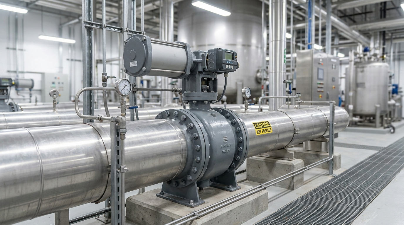
The flow coefficient, or Cv value, of a butterfly valve represents the volume of water at 60°F in US gallons that will flow through the valve per minute with a 1 psi pressure drop, which serves as the ultimate benchmark for system capacity. Imagine you are currently designing a high-capacity industrial pipeline where maintaining operational efficiency is your top priority. If you select the incorrect valve size, you risk choking your fluid flow or causing severe system turbulence. Balancing your butterfly valve pressure drop and Cv values solves this engineering challenge, giving you precise flow control and total system safety.
Why does butterfly valve pressure drop matter?
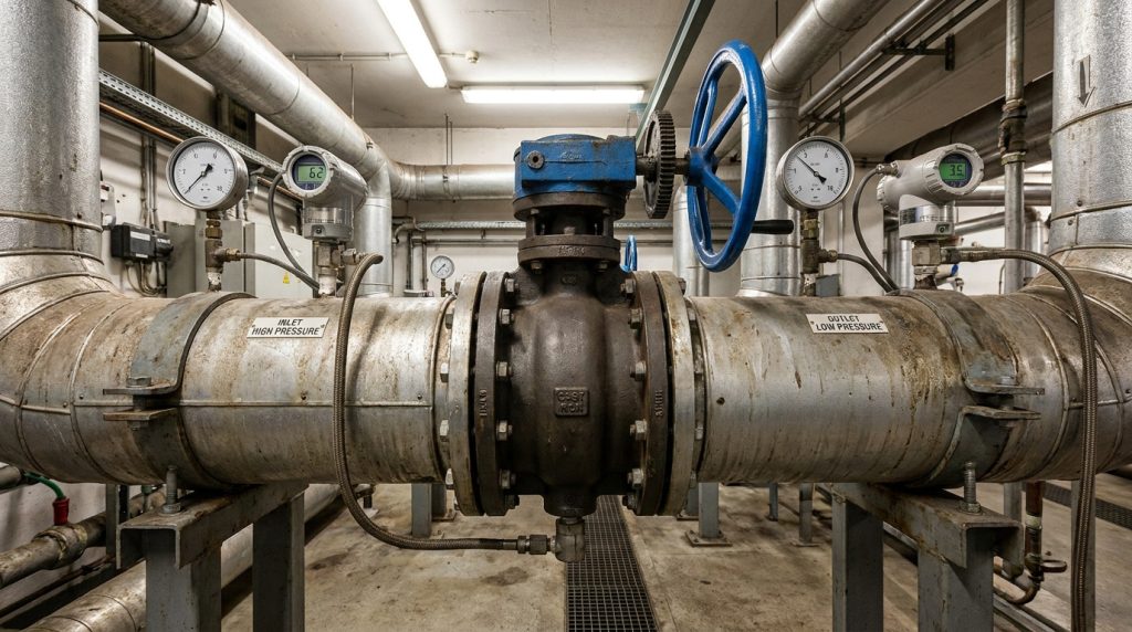
Understanding the impact of fluid friction is essential because excessive system resistance directly leads to costly energy losses and physical component degradation. You must constantly evaluate how butterfly valve pressure drop affects your operational budget and safety limits. This simple metric serves as the foundation for optimizing flow efficiency and preventing premature system failures.
How does pressure drop affect pump power?
Think about it: every extra pound of pressure your valve restricts is work your pumps must overcome. When resistance rises, your pumps must consume significantly more energy to maintain target flow rates.
- Higher motor temperatures reduce pump lifespan.
- Utility bills climb exponentially over time.
Does cavitation damage your system?
Let’s look closer: when fluid velocity spikes past the disc, localized pressure drops below vapor pressure, causing vapor bubbles to form. These bubbles collapse violently downstream and erode internal metal surfaces.
- Pitting on the disc destroys sealing performance.
- Micro-implosions cause severe pipeline vibration.
Key Takeaway: Preventing excessive head loss across the valve body protects your downstream piping assets from catastrophic cavitation wear.
| Pressure Drop Level | Cavitation Risk | Pump Power Impact | Recommended Action |
|---|---|---|---|
| Low (< 1 PSI) | Negligible | Minimum | Maintain current sizing |
| Moderate (1-5 PSI) | Moderate | Elevated | Monitor vibration levels |
| High (> 5 PSI) | Critical | High | Resize valve or modify trim |
This comparative matrix highlights how managing differential pressure levels protects both your mechanical infrastructure and your bottom line.
What causes butterfly valve pressure drop to rise?
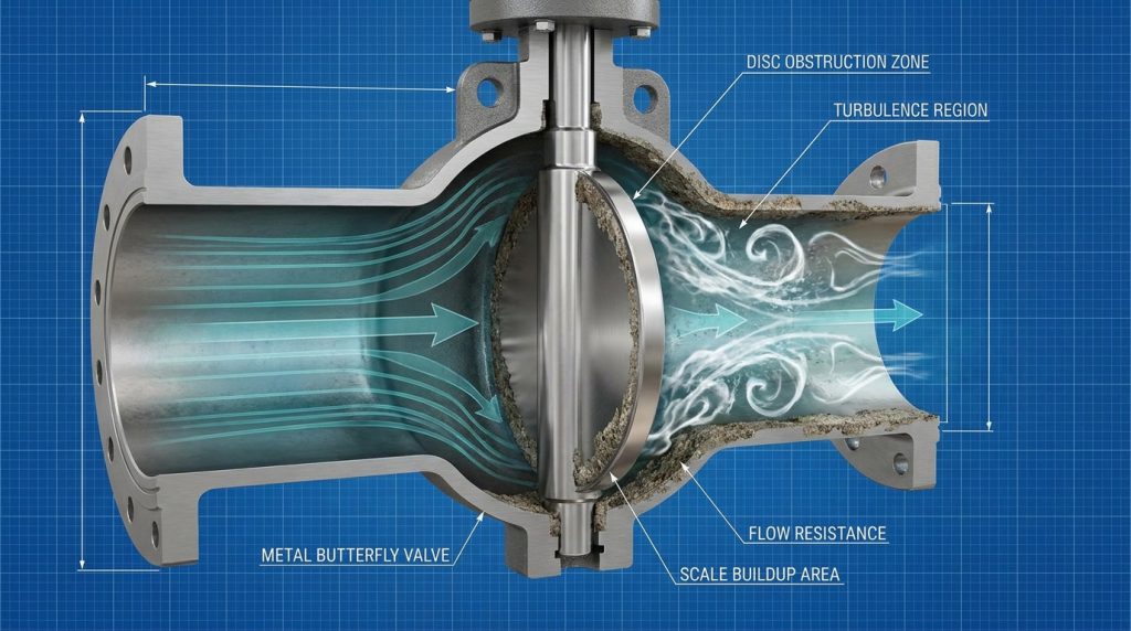
The escalation of fluid resistance is primarily driven by physical flow restrictions within the valve body, such as protruding disc profiles and internal particulate accumulation. Understanding how design and media factors trigger a sudden butterfly valve pressure drop allows you to anticipate performance bottlenecks. By identifying these variables early, you can design a more robust and predictable fluid system.
How do disc profiles obstruct flow?
Here is why: because a butterfly disc remains directly in the center of the flow stream even when fully open, it acts as a permanent minor obstruction. A thick or poorly shaped disc splits the fluid path and creates a wide, turbulent wake.
- Thicker profiles create larger low-pressure zones.
- Turbulence increases the overall friction coefficient.
Does slurry buildup increase resistance?
The best part? You can easily prevent solid deposition by maintaining adequate line velocity. When heavy particulates or slurries travel through a throttled valve, they can settle around the seat and disc, creating a physical dam.
- Accumulated solids restrict the net flow area.
- Solid buildup creates localized, high-velocity jets.
Key Takeaway: Selecting thin, hydrodynamically contoured discs and keeping line velocities high keeps fluid paths clear of debris.
| Obstruction Factor | Impact on Flow Area | Resistance Increase | Prevention Strategy |
|---|---|---|---|
| Thick Disc Profile | 10% – 15% Reduction | Moderate | Use contoured/thin discs |
| Slurry/Scale Buildup | 20% – 40% Reduction | High | Regular flushing cycles |
| Mechanical Wear | Variable | Low to Moderate | Hard-faced materials |
This analysis proves that minimizing internal physical blockages is key to keeping system head loss within design tolerances.
How to calculate butterfly valve pressure drop?
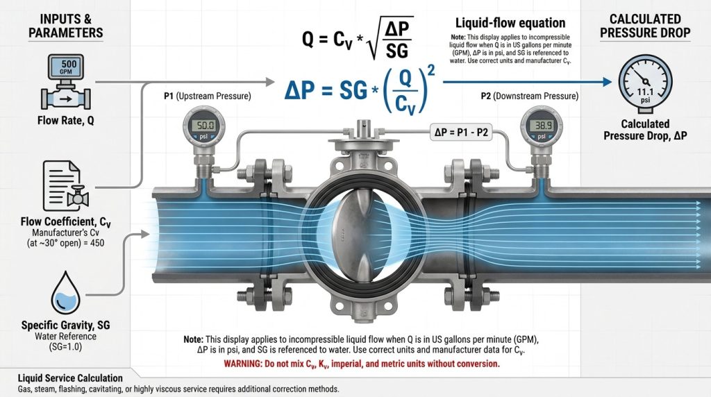
Calculating this fluid metric requires using the standard engineering equation that mathematically correlates flow rate, the valve’s Cv value, and fluid density. Utilizing this formula lets you accurately predict the butterfly valve pressure drop across various operating angles. Armed with these calculations, you can select pumps and sizing parameters with absolute confidence.
What is the standard Cv formula?
Let’s look closer: the core equation is a simple yet powerful tool for any system designer. By rearranging the standard formula, you can isolate the pressure differential variable ($\Delta P$) to find your expected loss.
- The formula is represented as $\Delta P = SG \times (Q / Cv)^2$.
- The variable $Q$ is your volumetric flow rate in GPM.
How does specific gravity play a role?
Think about it: a heavier, denser fluid requires more mechanical energy to accelerate through the valve than clean water. If you are pumping hydrocarbons or thick slurries, ignoring specific gravity will throw off your entire system design.
- High specific gravity liquids increase pressure loss.
- Light hydrocarbons lower the calculated drop.
Key Takeaway: Always verify your fluid’s exact specific gravity at operating temperature to ensure your sizing calculations remain precise.
| Fluid Medium | Specific Gravity (SG) | Calculated Cv Required | Resulting Loss (PSI) |
|---|---|---|---|
| Diesel Fuel | 0.85 | 100 | 0.85 |
| Pure Water | 1.00 | 100 | 1.00 |
| 30% Slurry | 1.25 | 100 | 1.25 |
The data demonstrates how fluid density scales head loss linearly, making specific gravity adjustments mandatory for non-water systems.
Can we reduce butterfly valve pressure drop?
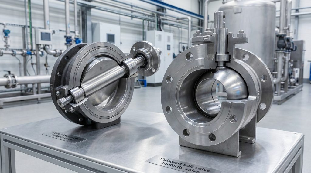
You can easily minimize flow resistance by selecting highly streamlined disc geometries, implementing full-port valve designs, and optimizing your piping layout. Actively working to reduce butterfly valve pressure drop pays massive dividends in energy savings and process stability. Small mechanical refinements can significantly lower your long-term operating costs.
Why choose a triple offset design?
Here is why: a triple offset design features a unique geometry that completely eliminates rubbing between the seat and disc during rotation. This non-rubbing action allows engineers to design thin, hydrodynamically optimized discs that slice through fluid.
- Streamlined disc edges minimize flow separation.
- Reduced friction allows for higher open-position Cv values.
How does full-port design lower loss?
The best part? A full-port or high-capacity valve ensures the internal diameter of the valve port matches your pipeline’s inner diameter. This matching eliminates sudden expansions or contractions that generate high-velocity turbulence.
- Smooth internal transitions prevent vortex shedding.
- Flow paths remain unrestricted from flange to flange.
Key Takeaway: Upgrading to a triple offset or full-port configuration is your best strategy for minimizing system drag and energy waste.
| Valve Design Option | Relative Port Area | Flow Path Turbulence | Pressure Drop Reduction |
|---|---|---|---|
| Standard Concentric | Moderate | Moderate | Baseline |
| Double Eccentric | High | Low | 15% Reduction |
| Triple Offset (Full-Port) | Maximized | Very Low | Up to 30% Reduction |
This comparison illustrates how moving toward advanced offset designs directly translates to cleaner flow paths and lower system friction.
Does disc style impact butterfly valve pressure drop?
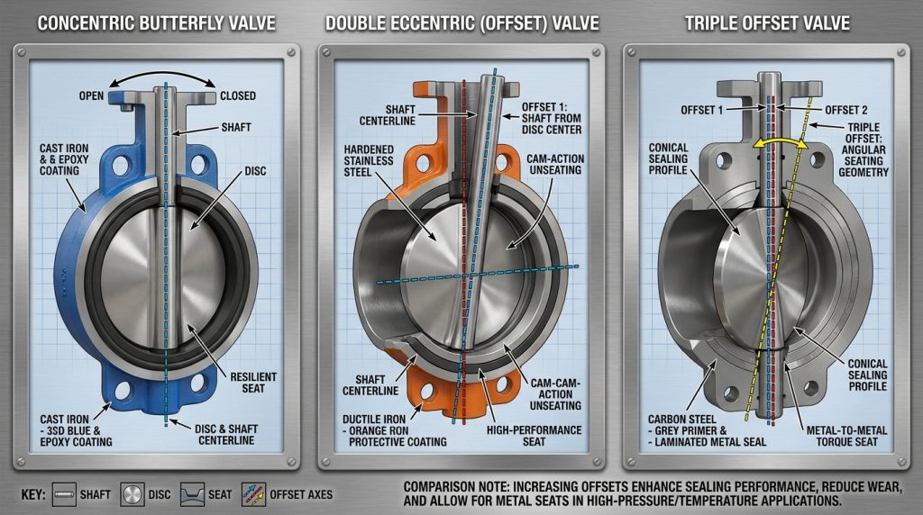
Yes, the physical layout of your valve’s disc style plays a major role because different mechanical geometries alter how fluid splits and merges around the central obstruction. Selecting the right disc style is crucial for managing your butterfly valve pressure drop during both full-flow and throttling scenarios. Each style is engineered to meet specific flow control and pressure limitations.
Is a concentric disc more restrictive?
Let’s look closer: in a concentric valve, the shaft runs straight through the centerline of the disc, which splits the flow symmetrically. While highly reliable for utility lines, this design requires a robust, thick seat and disc edge that can restrict flow.
- Continuous seat contact requires thicker profiles.
- Symmetrical splitting creates wake turbulence on both sides.
Why do eccentric discs perform better?
Think about it: by offsetting the shaft behind the disc, eccentric and high-performance valves pull the disc away from the seat instantly. This allows engineers to design a much thinner, more aerodynamic disc profile.
- Streamlined disc designs reduce trailing-edge wake.
- Lower profile thickness increases the net open area.
Key Takeaway: Choosing eccentric disc styles provides a more aerodynamic profile that maximizes Cv while protecting the sealing face.
| Disc Style | Shaft Location | Flow Obstruction | Throttling Performance |
|---|---|---|---|
| Concentric | Centered | Moderate | Good (Utility services) |
| Double Eccentric | Offset (Double) | Low | Excellent (Industrial) |
| Triple Offset | Offset (Triple) | Very Low | Outstanding (High Pressure) |
The data highlights how shifting the shaft axis allows for more streamlined profiles that elevate overall system capacity.
How does sizing affect butterfly valve pressure drop?
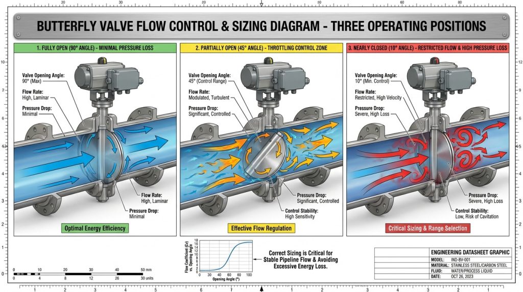
Proper sizing is the single most critical factor in fluid system design because an incorrectly scaled valve either restricts flow or destroys control resolution. Balancing your valve size against system requirements is the only way to keep your butterfly valve pressure drop in a safe, predictable range. Sizing should never be done by simply matching the pipe diameter without checking Cv requirements.
Is your valve operating under 20 degrees?
Think about it: operating a butterfly valve at very small opening angles forces fluid through tiny, high-velocity gaps. This causes extreme pressure differentials that can quickly destroy your seat and disc.
- Operating below 20 degrees causes severe seat erosion.
- Control sensitivity becomes unstable and erratic.
What are the risks of an undersized valve?
Here is why: an undersized valve acts as a permanent bottleneck, forcing your pumps to work significantly harder to maintain the required flow rate. The resulting system head loss will constantly waste energy and throttle your production capacity.
- Line capacity becomes severely restricted.
- Downstream processes suffer from pressure starvation.
Key Takeaway: Always size your valve so that your normal operating flow rate falls within the stable 30-to-70-degree disc opening range.
| Opening Angle | Flow Zone Status | Risk Level | Control Quality |
|---|---|---|---|
| 10° – 20° | Highly Restrictive | Critical Wear | Erratic & Hyper-Sensitive |
| 30° – 70° | Stable Control | Low Wear | High Resolution |
| 80° – 90° | Maximum Flow | Safe Operation | Poor Control Sensitivity |
This breakdown shows why keeping your valve out of extreme open or closed positions is critical for stable flow dynamics.
When is butterfly valve pressure drop dangerous?
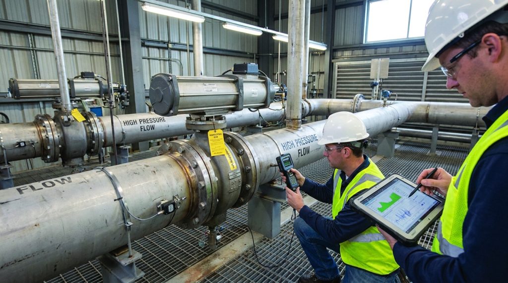
High resistance becomes highly dangerous when it triggers phase changes like flashing or causes fluid velocities to exceed safe mechanical limits. You must monitor operational conditions to prevent a dangerous butterfly valve pressure drop from compromising pipeline structural integrity. Ignoring these risks can lead to catastrophic system failures and costly emergency shutdowns.
When does flashing occur in your line?
Let’s look closer: flashing happens when the pressure drop across the valve falls below the liquid’s vapor pressure, and the pressure remains low downstream. This causes the fluid to vaporize into gas bubbles that stay in the line.
- Flashing chokes your flow, limiting max capacity.
- The two-phase gas-liquid mix causes extreme vibration.
How does high velocity cause erosion?
The best part? You can easily prevent high-velocity erosion by enforcing strict velocity limits in your system piping. When fluid speeds exceed safe levels, the kinetic energy rapidly wears down internal surfaces, especially around the throttled disc.
- Abrasive wear eats away at soft seats.
- Disc edges lose their precise seal profiles.
Key Takeaway: Keeping fluid velocities within industry-recommended limits eliminates flashing and prevents premature erosion of your valve components.
| Operating Hazard | Cause | System Impact | Primary Prevention |
|---|---|---|---|
| Flashing | Low downstream pressure | Choked flow, vibration | Raise backpressure |
| Severe Erosion | Excessive velocity (>20 ft/s) | Thinning metal, leaks | Upsize pipe & valve |
| Acoustic Noise | Sonic gas speeds | Structural damage | Install silencers/diffusers |
These hazards illustrate why managing velocity is just as important as matching your calculated Cv value.
How to monitor butterfly valve pressure drop?
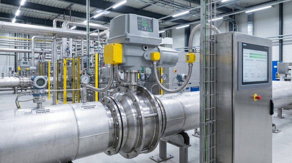
Monitoring fluid resistance is best achieved by installing differential pressure transmitters upstream and downstream of the valve or utilizing smart pneumatic actuators. Continuous tracking of your butterfly valve pressure drop provides real-time diagnostics of internal valve health and calibration. This data allows you to transition your plant from reactive troubleshooting to proactive, predictive maintenance.
Where should transmitters be placed?
Think about it: placing your pressure sensors too close to the valve will yield highly inaccurate readings due to local turbulence. To capture clean, stable pressure data, you must locate them in straight runs of pipe.
- Upstream sensor: 2 to 5 pipe diameters away.
- Downstream sensor: 6 to 10 pipe diameters away.
Can smart actuators track head loss?
Here is why: modern smart positioners continuously track the exact angle of the disc and cross-reference it with system flow rates. By comparing this data to pre-programmed Cv curves, the actuator can calculate and report head loss instantly.
- Smart actuators flag performance deviations early.
- They detect seat wear or disc slipping automatically.
Key Takeaway: Utilizing smart positioners and proper transmitter placement gives you a clear window into your valve’s operational efficiency.
| Monitoring Method | Parameter Tracked | Main Advantage | Ideal Application |
|---|---|---|---|
| DP Transmitters | Direct pressure loss | Absolute accuracy | Critical process lines |
| Smart Actuators | Disc angle & travel | Predictive diagnostics | Automated plants |
| Manual Gauges | Visual pressure differential | Low cost | Utility & water lines |
This comparison shows how shifting to digital monitoring provides the rich data needed for modern predictive plant maintenance.
Which seat prevents butterfly valve pressure drop?
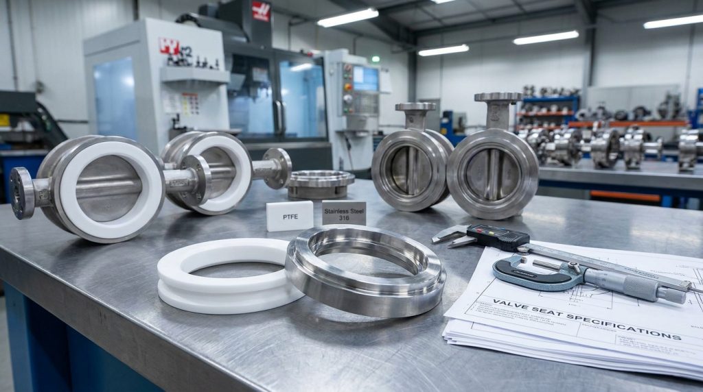
High-performance seats like flexible PTFE or hard-faced metal-to-metal designs prevent excess resistance by allowing for thinner, more streamlined disc profiles. Selecting the optimal seat material is a critical design step to keep your butterfly valve pressure drop low while securing a bubble-tight seal. The right seat ensures your valve maintains its original flow characteristics under extreme conditions.
How do PTFE seats reduce drag?
Let’s look closer: PTFE is a self-lubricating, low-friction material that requires very little mechanical torque to achieve a tight seal. This allows the valve disc to be designed with a highly streamlined, thin edge.
- Low surface friction minimizes localized boundary drag.
- PTFE resists chemical swelling that restricts flow paths.
Why are metal-to-metal seats durable?
The best part? Metal-to-metal seats are designed to handle extreme temperatures and abrasive slurries without eroding or deforming. This rugged durability ensures that the internal flow geometry remains perfectly intact over years of service.
- Hard-faced alloys resist slurry scouring.
- Zero swelling ensures consistent Cv ratings.
Key Takeaway: Upgrading to PTFE or metal seats protects your flow path geometry from warping under high pressures and temperatures.
| Seat Material Type | Max Temperature | Sealing Class | Flow Resistance Impact |
|---|---|---|---|
| Standard EPDM | 250°F (121°C) | Class VI (Bubble-Tight) | Moderate to High |
| Flexible PTFE | 400°F (204°C) | Class VI (Bubble-Tight) | Low |
| Hardened Metal | 1000°F (538°C) | Class IV or V (Tight) | Very Low |
This evaluation highlights how advanced materials allow engineers to optimize sealing performance without sacrificing flow capacity.
Can piping design lower butterfly valve pressure drop?
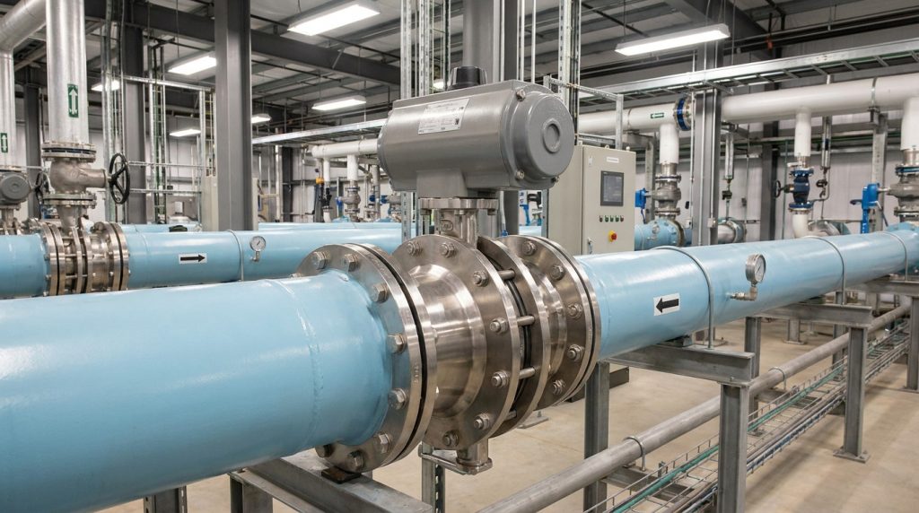
Yes, optimizing your piping layout by eliminating close-coupled fittings and ensuring smooth fluid transitions will significantly reduce overall system head loss. Proper piping practices ensure that fluid enters the valve in a stable state, preventing any artificial rise in butterfly valve pressure drop. Designing your piping with flow dynamics in mind is the secret to peak system efficiency.
Why avoid elbows near the valve?
Think about it: placing an elbow directly upstream of a butterfly valve creates a highly turbulent, asymmetrical flow velocity profile. When this uneven fluid hits the disc, it creates massive wake turbulence and raises pressure loss.
- Asymmetrical flow forces more fluid to one side of the disc.
- Localized velocity spikes increase friction and wear.
How do pipe reducers affect stability?
Here is why: sudden, sharp reductions in pipe diameter right before the valve generate severe vortex shedding and fluid shear. Using gradual concentric reducers ensures a smooth transition that keeps fluid flowing cleanly.
- Concentric reducers preserve a symmetrical velocity profile.
- Gradual slopes minimize turbulence and head loss.
Key Takeaway: Ensuring straight, unobstructed pipe runs before and after your butterfly valve is essential for maintaining predictable flow characteristics.
| Piping Configuration | Flow Profile Status | Impact on Pressure Loss | Best Design Practice |
|---|---|---|---|
| Elbow Upstream | Highly Turbulent | 20% – 30% Increase | 5x Pipe Diameter Spacer |
| Sudden Reducer | High Shear | 15% – 25% Increase | Use Gradual Concentric Reducers |
| Straight Pipe Run | Fully Developed | Baseline (Minimal) | 10x Upstream / 5x Downstream |
This data confirms that the structural design of your piping network directly impacts the hydrodynamic efficiency of your valves.
Conclusion
By mastering the relationship between the flow coefficient (Cv) and pressure drop, you can eliminate the costly trial-and-error often associated with industrial pipeline design. From choosing advanced offset discs to optimizing your piping configurations, this guide provides the exact blueprints you need to secure a high-capacity, low-maintenance fluid system. At RUITO, we believe that every valve we manufacture is a promise of engineering excellence, built to optimize your plant’s performance and safeguard your assets. If you are ready to elevate your system’s efficiency with certified, high-performance flow control solutions, contact us today to collaborate with our expert application engineers.
Frequently Asked Questions
Can I use a butterfly valve for high-pressure throttling services?
Yes, but only if you select a high-performance double or triple offset butterfly valve. Standard concentric butterfly valves are highly prone to rapid seat wear and unstable control characteristics when subjected to continuous high-differential pressures. High-performance offset designs lift the disc clear of the seat immediately, protecting the seal and allowing for fine-tuned throttling.
What’s the best way to prevent cavitation in my system?
The most effective way is to maintain fluid velocity below 20 feet per second and operate the valve within its optimal opening range. If your application demands a very high pressure drop, consider utilizing multi-stage trim or installing a downstream restriction orifice to share the pressure reduction workload. This approach keeps localized fluid pressure from dropping below vapor pressure.
How do I know if my butterfly valve is oversized?
You will know a valve is oversized if your control loop is constantly hunting or if your normal flow rate requires an opening angle of less than 20 degrees. Oversized valves cause rapid actuator wear and make it extremely difficult to maintain stable system pressure. They also lead to severe seat erosion because fluid is forced through tiny, high-velocity gaps.
Can I rely on generic Cv charts for my final pipeline designs?
No, you should never rely on generic charts for final engineering calculations because flow coefficients vary significantly between valve brands. Always verify your final designs using certified testing data supplied by the specific manufacturer. This ensures your calculations for pressure drop and required actuator torque are 100% accurate.
How do I select the best seat material for handling slurry pressure drops?
You should choose a hard, resilient elastomer liner like polyurethane or a solid metal-to-metal seat. These robust materials are engineered to withstand the continuous scouring and abrasive wear of suspended solids. By resisting erosion, they preserve the valve’s internal geometry and maintain predictable pressure drop characteristics over years of heavy-duty operation.