
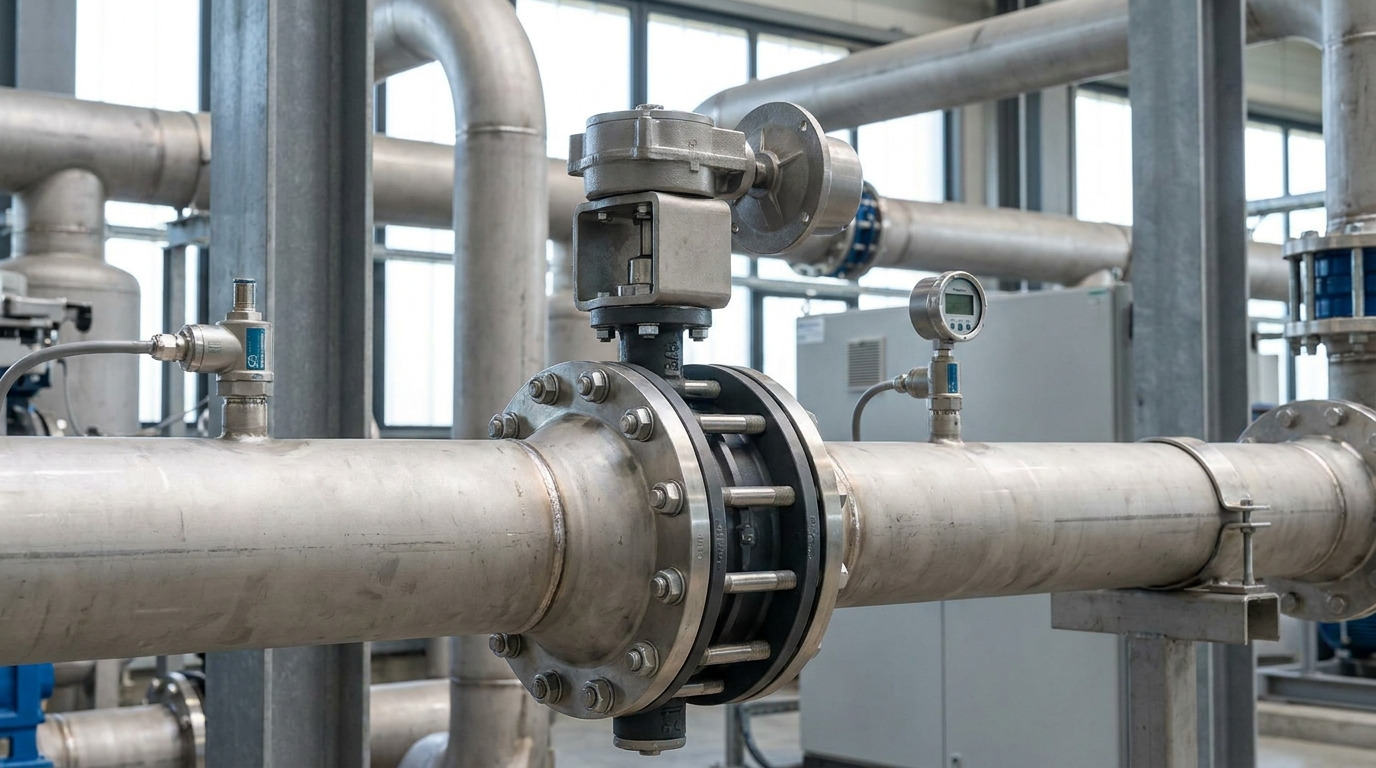
Butterfly valve pressure drop can be calculated with a model-specific Cv or Kv value, or with a K factor, at the actual disc position—but the result is valid only for the fluid and operating conditions assumed by that method. A fully open valve still creates resistance because its disc and shaft remain in the bore; a partly closed valve can create much more loss as it redirects the flow through a smaller effective area.
This matters when pump head is limited or an automated valve must throttle smoothly. Choose the right coefficient, calculate more than one operating point, and verify that it belongs to the exact industrial butterfly valve design and disc angle you intend to buy.
What Butterfly Valve Pressure Drop Actually Means
Butterfly valve pressure drop is the difference between the static pressure upstream and downstream of the valve at a stated flow condition. It is a local loss produced by flow separation, turbulence, and friction as the fluid passes the disc, shaft, seat, and body transitions.
“Low pressure drop” is therefore not a fixed property of every butterfly valve. It describes a condition: one valve design, one opening, one flow rate, and one fluid state. Change the disc angle or double the flow, and the pressure loss may change sharply.
Do not confuse valve differential pressure with total circuit loss. Pump head calculations must also include pipe, fittings, equipment, and elevation. The valve calculation covers only the valve unless its coefficient incorporates adjacent piping effects.
Use Cv or Kv for a Known Operating Point
Use Cv or Kv when the manufacturer provides a flow coefficient for the exact valve size, construction, and opening angle. Cv is convenient for U.S. customary units, while Kv provides the corresponding metric capacity basis.
Liquid pressure drop from Cv
For a water-like, turbulent, non-flashing liquid, the simplified relationship is:
ΔP = SG × (Q / Cv)²
Where:
ΔP= pressure drop in psiQ= liquid flow in U.S. gpmSG= specific gravity relative to waterCv= coefficient at the actual disc position
For a hypothetical water line flowing at 600 gpm, a Cv of 1,200 gives a 0.25 psi drop. At the same flow, a Cv of 600 gives 1 psi, and a Cv of 300 gives 4 psi. This square relationship is the reason a change in opening angle can have a much larger hydraulic effect than the travel change suggests.
Metric pressure drop from Kv
With Q in m³/h and ΔP in bar, the analogous simplified relationship is:
ΔP = SG × (Q / Kv)²
Keep the calculation in one unit system; do not insert Cv into the Kv equation or mix gpm, m³/h, psi, and bar. For more on inherent and installed curves, see butterfly valve flow characteristics.
Use K for System Head-Loss Models
Use the resistance coefficient K when you are building a piping-system loss model from velocity and density. K is dimensionless and is normally applied as:
ΔP = K × ρv² / 2
Or as head loss:
hL = K × v² / (2g)
Here, ρ is density, v is mean pipe velocity, and g is gravitational acceleration. Use this form when adding valve loss to other local restrictions.
Cv and K describe related behavior but are not interchangeable. Conversion depends on diameter, units, geometry, and test basis. Use the butterfly valve K-factor method with the correct size and opening; use Cv for capacity selection from a manufacturer’s curve.
The choice can be summarized as follows:
| Engineering task | Preferred input | Main calculation | Critical check |
|---|---|---|---|
| Valve capacity or sizing | Cv or Kv | Flow versus valve differential pressure | Exact series, size, and disc position |
| Total piping head loss | K | Velocity head multiplied by local resistance | Correct bore velocity and operating angle |
| Preliminary screening only | Generic coefficient | Approximate loss | Replace with model-specific data before purchase |
Choose the coefficient that matches the published basis and engineering task.
Match the Coefficient to the Disc Position
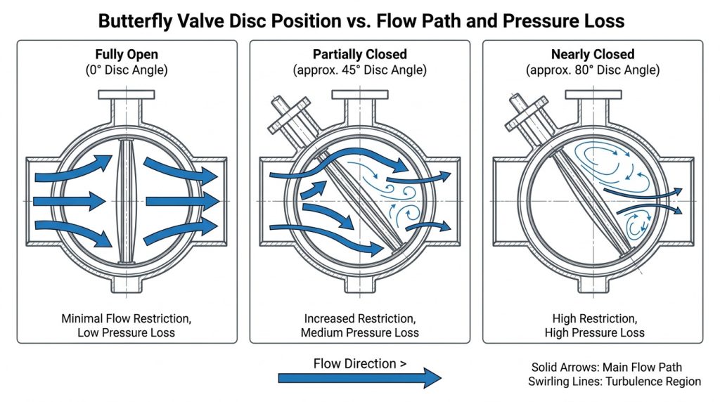
The coefficient must match the actual disc position because butterfly-valve capacity does not change linearly with travel. A value at full open cannot predict the loss at a throttling position, and “50% open” does not mean 50% of full-open Cv.
Read the chart legend before using any number. Some documents show degrees open, with 90° representing fully open; others show degrees from the fully open position, with 0° representing fully open. Percent travel, actuator feedback, and disc angle may also use different conventions. Confirm the reference position on the drawing or data sheet instead of inferring it from the column heading.
Confirm that the chart matches the body pattern, pressure class, seat, disc, shaft, and nominal size. Valves with the same DN or NPS can differ because their obstruction and pressure recovery differ. Generic tables are for early comparison, not final design.
Check Every Operating Point, Not One Design Point
A defensible selection must work at minimum, normal, and maximum flow, not only at the design maximum. One calculation may prove that the valve passes peak flow while hiding unstable control at normal demand or excessive loss near the low-flow position.
Build a three-point worksheet
For each operating point, record:
- Flow rate and fluid temperature.
- Upstream and downstream pressure available at that flow.
- Density or specific gravity, plus viscosity and vapor pressure when relevant.
- Required Cv or Kv from the allowable valve pressure drop.
- Disc angle that delivers that coefficient on the selected curve.
- Resulting velocity, actuator torque requirement, and cavitation or noise warning.
The normal point should allow useful control in both directions. Near-closed normal operation suggests oversizing; near-fully-open maximum operation leaves little reserve. An ISA process-control sizing chapter links oversizing with high gain, poor accuracy, instability, and potential damage.
Sizing down is not an automatic cure. A smaller valve may move the normal point into a better travel range, but it can also raise velocity, noise, cavitation risk, torque, and reducer losses. Recalculate all three points before changing size.
Know When the Simple Equations Are Not Enough
The simplified liquid equations are not enough when density changes materially, vapor forms, viscosity corrections matter, or the flow is not a single-phase Newtonian liquid. Gas, steam, flashing liquid, cavitating service, slurries, non-Newtonian fluids, and two-phase flow need a suitable control-valve sizing method and additional coefficients.
The scope of IEC 60534-2-1 is useful here: it covers installed sizing equations for compressible and incompressible fluids, while its incompressible equations are not intended for non-Newtonian fluids, slurries, or liquid-solid transport. That boundary prevents a neat liquid Cv result from being treated as a universal answer.
For liquid throttling, compare the lowest local pressure with the liquid’s vapor pressure and review the valve’s pressure-recovery data. Noise, vibration, pitting, unstable flow, or rapid seat damage are warning signs, not corrections to add after the calculation. For severe pressure letdown or precise low-flow control, a purpose-selected globe valve or another control-valve style may be more appropriate.
Adjacent reducers, elbows, and disturbed inlet flow can shift installed capacity from the bare-valve test condition. Where the sizing method includes piping-geometry factors, model the actual arrangement.
Verify the Data Before Procurement
Final procurement should rely on a model-specific Cv, Kv, or K curve with its test basis—not only a generic chart, a calculator, or a pressure-test certificate. The data package should identify valve series, nominal size, pressure class, body style, disc and seat design, opening convention, fluid basis, units, and whether the values represent bare-valve or installed conditions.
Keep hydraulic evidence separate from integrity evidence. ISO 5208 covers pressure-boundary integrity, closure tightness, and closure-mechanism adequacy; it does not establish a valve’s Cv curve. A shell or seat test can confirm that a valve withstands pressure and closes to the specified leakage criterion, but it cannot prove the pressure drop at a stated flow and disc angle.
For a project review, provide fluid, temperature, three-point flow and pressure data, line size, flange standard, duty, leakage requirement, actuation, fail position, and allowable drop. RUITO’s published range includes concentric, double-eccentric, and triple-eccentric constructions, so hydraulic data must be tied to the proposed construction.
Turn the Calculation into a Defensible Selection
A reliable butterfly-valve pressure-drop decision combines the right equation, an angle-specific coefficient, all operating points, and a check of the method’s fluid limits. Cv or Kv is usually the clearest route for valve capacity, while K fits a complete system head-loss model; neither is trustworthy if it comes from the wrong valve or opening.
RUITO can review the proposed construction together with your operating data and documentation requirements. To move from a preliminary estimate to a project-specific selection, send your operating conditions for a technical review.
FAQ
Can I estimate pressure drop without manufacturer Cv data?
Yes, but only as a preliminary estimate. A generic Cv or K value can support concept-stage pump or piping checks, but final sizing should use coefficient data for the exact valve series, size, and opening angle.
Why can two butterfly valves of the same size have different drops?
Their internal geometry can differ. Disc thickness and profile, shaft obstruction, seat shape, body bore, offset construction, and pressure class can all change flow separation and recovery.
Does selecting a smaller butterfly valve always improve control?
No. A smaller valve may move normal operation away from the nearly closed region, but it also raises velocity and may increase noise, cavitation, torque, and transition losses.
What pressure-drop data should I include in an RFQ?
Include minimum, normal, and maximum flow; upstream and downstream pressure at each point; fluid and temperature; density or specific gravity; viscosity and vapor pressure when relevant; line size; allowable drop; valve duty; and the required actuation and shutoff condition.