
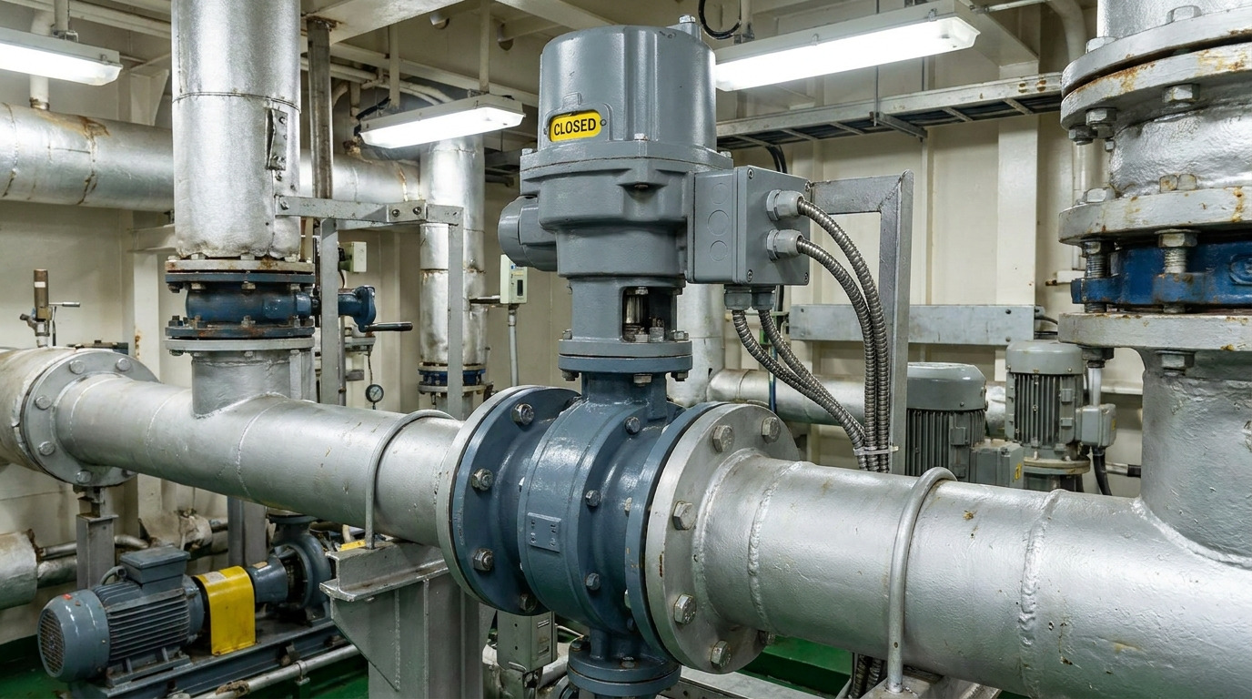
A marine electric butterfly valve should be selected as a complete valve-actuator-control package, not by valve size or IP rating alone. On a ballast, seawater-cooling, bilge, or fire-main line, the valve may fit between the flanges yet still fail the project because the seat is incompatible, the actuator cannot close at maximum differential pressure, the control signal is wrong, or the approval documents do not cover the supplied configuration.
The practical solution is to lock the process duty, valve construction, actuator sizing basis, electrical interface, environmental conditions, and inspection documents before requesting a quote. The checklist below gives engineers and procurement teams a common specification that can be evaluated and tested.
Confirm That Electric Actuation Fits the Duty
Electric actuation fits duties that need remote operation, position feedback, repeatable sequencing, or integration with a shipboard control system. A butterfly valve adds a compact quarter-turn flow element, which is useful where machinery-space access and piping weight are constrained.
The first decision is whether the valve provides isolation, throttling, or both. An on-off actuator is not automatically suitable for continuous modulation, while a modulating actuator does not correct poor valve sizing or an unstable operating range. Record the required stroke time, cycle frequency, positioning accuracy, and allowable response after a control or power failure.
Typical candidates include ballast transfer, central cooling, fire water, freshwater services, and selected bilge duties. Fuel, oily water, chemically dosed water, and abrasive mixtures require a separate compatibility review; “marine service” is not a fluid specification.
Define the Fluid and Operating Envelope First
The operating envelope must describe the worst condition the assembly will see, not just the normal gauge reading. Actuator torque, seat life, corrosion resistance, and shutoff performance can all change with pressure differential, temperature, solids, flow velocity, and time between cycles.
Use this duty sheet before choosing materials:
| Required input | What to record | Why it changes the selection |
|---|---|---|
| System and medium | Seawater, freshwater, fire water, bilge mixture, fuel, air, or another fluid; include concentration and treatment chemicals | Determines wetted-material and elastomer compatibility |
| Pressure | Design pressure, normal pressure, maximum differential pressure, surge or vacuum condition | Sets the valve rating and the actuator’s closing load |
| Temperature | Fluid minimum/maximum and local ambient minimum/maximum | Affects seat behavior, motor rating, grease, electronics, and condensation risk |
| Flow condition | Design and maximum flow, throttling range, solids, fouling, and expected velocity | Affects Cv, dynamic torque, erosion, and blockage risk |
| Operating pattern | Isolation or control, cycles per hour/day, long idle periods, and required stroke time | Sets actuator duty and the allowance for rising breakaway torque |
| Safe response | Fail-open, fail-close, remain in position, or controlled shutdown | Determines stored energy, backup power, and control logic |
For a seawater line, evaluate the external atmosphere separately from the internal fluid. A coated body may resist engine-room humidity while its disc, shaft, seat, and fasteners still need their own compatibility decisions. Conversely, corrosion-resistant wetted parts do not prove that the actuator enclosure, cable entries, or mounting hardware will survive exposed salt spray.
Specify Valve Construction and Pipe Connection
Valve construction should be specified component by component and matched to the pipe standard. RUITO’s industrial butterfly valve range lists DN25-DN3000 and PN10-PN25 configurations, with ductile iron, cast iron, carbon steel, stainless steel, and duplex body options; EPDM, NBR, PTFE, FKM, and metal seats; and wafer, lug, or flanged connections. These are available options, not a universal material recommendation.
Confirm at least the body, disc, shaft, seat, coating or lining, fasteners, and any galvanic-isolation requirement. The seat must be checked against the actual fluid mixture and temperature. The disc and shaft need review for continuous immersion, chloride exposure, erosion, and contact with dissimilar piping materials. Ask the supplier to state the exact material grades rather than using labels such as “stainless” or “marine grade.”
Connection style is an installation and isolation decision:
- A wafer body is compact and economical, but it normally depends on the two pipe flanges and through-bolting.
- A lug body can support one-sided pipe removal only when its design, bolting, pressure direction, and dead-end rating explicitly permit that service.
- A double-flanged body provides an independent bolted connection on each side and may suit larger sizes or permanent installations, but it adds weight and face-to-face length.
Use the actual flange drilling, face-to-face dimension, gasket arrangement, and disc-clearance envelope to make the final choice. This wafer-versus-lug selection guide explains the piping constraints in more detail.
Size the Actuator as Part of the Valve Assembly
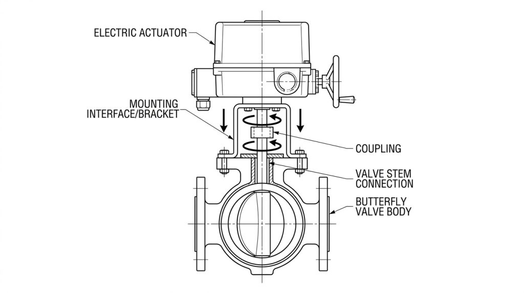
The actuator must be sized from the valve manufacturer’s torque data for the stated duty, then verified as part of the assembled package. ISO 5115:2023 treats a part-turn actuated valve as an assembly comprising the valve, actuator, and mounting kit where required, and defines the information and responsibilities needed for sizing, selection, and assembly.
Ask for the seating, unseating, running, and dynamic torque basis at the maximum specified differential pressure and temperature. The calculation should consider seat material, direction of pressure, fluid velocity, solids or scale, long idle periods, operating frequency, and expected degradation. Agree on a service factor with the supplier; do not apply an unexplained percentage to an unknown torque value.
Also verify the full mechanical load path: actuator output, gearbox if used, mounting flange, bracket, coupling, key or drive profile, valve stem, and mechanical stops. Nominal interface compatibility does not prove that the coupling, bracket stiffness, backlash, or stem capacity is adequate. A factory functional test of the assembled unit is more useful than separate certificates for an unmounted valve and actuator.
Match Power, Controls, and the Safe Failure Position
The electrical specification must define how the actuator is powered, commanded, monitored, and moved during an abnormal event. Listing only “electric actuator” leaves several interfaces unresolved.
Include these items in the datasheet:
- Supply voltage, AC or DC, frequency and phase, allowable voltage variation, starting current, and available circuit protection.
- On-off or modulating duty, command signal, control protocol, required resolution, and permissible cycle rate.
- Open/closed limit contacts, analog position feedback, torque or fault alarms, local indicator, and remote/local selector requirements.
- Required action on loss of power or signal: fail-open, fail-close, remain in place, or move under an external emergency supply.
- Manual override method, access clearance, anti-condensation heater, cable-gland arrangement, terminal format, and space for maintenance.
For modulating service, provide the design flow, pressure drop, required controllable range, and valve characteristic. The actuator must position the disc repeatably within the useful control region; it should not spend normal operation near a highly sensitive or unstable angle. This guide to butterfly valve flow characteristics shows why pipe-size matching alone is not a control-valve calculation.
Do not assume an electric actuator will move during a blackout. Many units remain in their last position unless the package includes a spring mechanism, capacitor, battery, UPS, or another stored-energy source. The required safe position should come from the system hazard analysis, and the backup method must be able to complete the stroke at the worst specified torque.
Separate IP Rating, Corrosion Protection, and Marine Approval
IP rating, corrosion resistance, and marine approval answer three different questions and should be verified separately. The IEC definition of enclosure protection covers protection against contact, solid foreign objects, and harmful water ingress; it does not by itself establish salt-spray durability, vibration resistance, hazardous-area suitability, or acceptance by a classification society.
For each installation location, specify whether the actuator is in a dry machinery room, humid compartment, exposed deck, washdown area, splash zone, or an area at risk of flooding. Then request evidence for the relevant enclosure rating, ambient-temperature range, external coating or housing material, cable glands, condensation control, vibration and shock, and electromagnetic compatibility. Continuous immersion must be stated explicitly rather than inferred from a general IP label.
If type approval is required, name the classification society, vessel or project, rule edition, equipment location, and required certificate type in the RFQ. IACS UR E10 is a test specification for type approval of electrical, electronic, and programmable equipment, but the project’s class rules determine whether and how it applies. Always confirm that a certificate is current and that its scope covers the exact actuator model, rating, options, and supplied valve package.
Verify Installation and Commissioning Details
Installation readiness should be proven on drawings and then confirmed by functional checks on the assembled valve. Start with the flange standard and pressure class, face-to-face dimension, disc swing clearance, gasket position, preferred shaft orientation, actuator height, cable-entry direction, support requirements, and access to the override and terminal compartment.
Before energizing, move the valve through its travel manually and investigate any binding. Set mechanical stops and electrical limits to the valve manufacturer’s procedure, then confirm that local indication, remote status, and the actual disc position agree. This guide to confirming butterfly valve position distinguishes travel indication from verified shutoff.
The commissioning record should include powered open/close tests at the installed supply, stroke time, motor current or torque alarms, command and feedback checks, manual-override operation, and the defined power-loss or signal-loss response. Finish with the specified shell or seat test, or an installed leakage check where the project procedure permits it. Record the actuator settings and terminal schedule so a later replacement does not depend on guesswork.
Convert the Requirement into an RFQ and Inspection Plan
A useful RFQ lets every bidder quote the same assembly and lets the inspector verify what was ordered. Copy the following fields into the valve datasheet or material requisition:
| RFQ block | Minimum information to include |
|---|---|
| Service | Shipboard system, medium composition, solids, cleaning chemicals, location, and criticality |
| Hydraulic duty | DN, design pressure, maximum differential pressure, temperature range, flow/Cv data, shutoff direction, and leakage requirement |
| Valve | Design type, pressure rating, end connection, flange and face-to-face standards, body/disc/shaft/seat grades, coating, and fasteners |
| Actuator and mount | Required output torque with sizing basis, service factor, duty rating, stroke time, mounting interface, bracket, coupling, and override |
| Electrical and controls | Supply, starting current, on-off/modulating function, command, feedback, alarms, protocol, and terminal diagram |
| Failure response | Required fail position, loss-of-signal action, energy source, and test method |
| Environment | Ambient range, IP requirement, salt-spray or coating requirement, condensation control, vibration/EMC, and hazardous-area classification if applicable |
| Approval and records | Class society and certificate scope, approved drawings, material certificates, pressure/leakage reports, actuator functional report, IOM manual, and nameplate data |
| Commercial | Quantity, commissioning and operational spares, delivery sequence, packing, inspection hold points, and warranty documents |
RUITO’s marine production information lists material verification, dimensional checks, assembly torque and alignment monitoring, and hydrostatic or pneumatic seat tests. Its marine valve testing protocols specify a shell test at 1.5 times PN, a high-pressure seat test at 1.1 times PN, and a low-pressure pneumatic seat test at 0.6 MPa for the listed scope. Your purchase order should still state the governing standard, acceptance criteria, duration, test medium, witnessing requirement, and records required for the exact valve.
Compare quotations line by line against this completed datasheet. A lower-priced package is not equivalent if its torque basis, certificate scope, feedback hardware, coating system, or test documentation is missing.
Specify the Complete Package Before Comparing Quotes
Reliable procurement starts with one controlled specification for the duty, valve, actuator, controls, environment, approval scope, and acceptance tests. That approach exposes interface gaps before production and gives commissioning teams a traceable baseline after installation.
RUITO can review your process data, pipe interface, actuator requirements, material combination, inspection plan, and delivery documents as one package. Send the completed checklist through our project contact page to request a technical review or quotation.
Frequently Asked Questions
Is an IP67 actuator automatically suitable for an exposed deck?
No. IP67 addresses enclosure ingress under defined test conditions, but exposed-deck suitability also depends on corrosion protection, cable entries, condensation control, temperature, vibration, washdown conditions, and any project-specific class requirements.
Can a wafer butterfly valve be used for dead-end service?
Only when the manufacturer explicitly rates that exact valve, pressure direction, bolting arrangement, and pressure for dead-end duty. Do not infer dead-end capability from the word “wafer” or from the valve’s normal bidirectional shutoff rating.
Does an actuator type-approval certificate cover the whole valve package?
Not necessarily. Check the certificate’s product designation, ratings, options, limitations, and validity, then confirm whether the project requires approval or product certification for the actuator alone, the valve, or the assembled unit.
Which spare parts should be ordered with the valve?
Order spares against the approved bill of materials and equipment criticality. Common candidates include the exact seat or seal kit, stem seals, actuator limit or feedback components, fuses, and a configured replacement actuator for duties where downtime is unacceptable.