
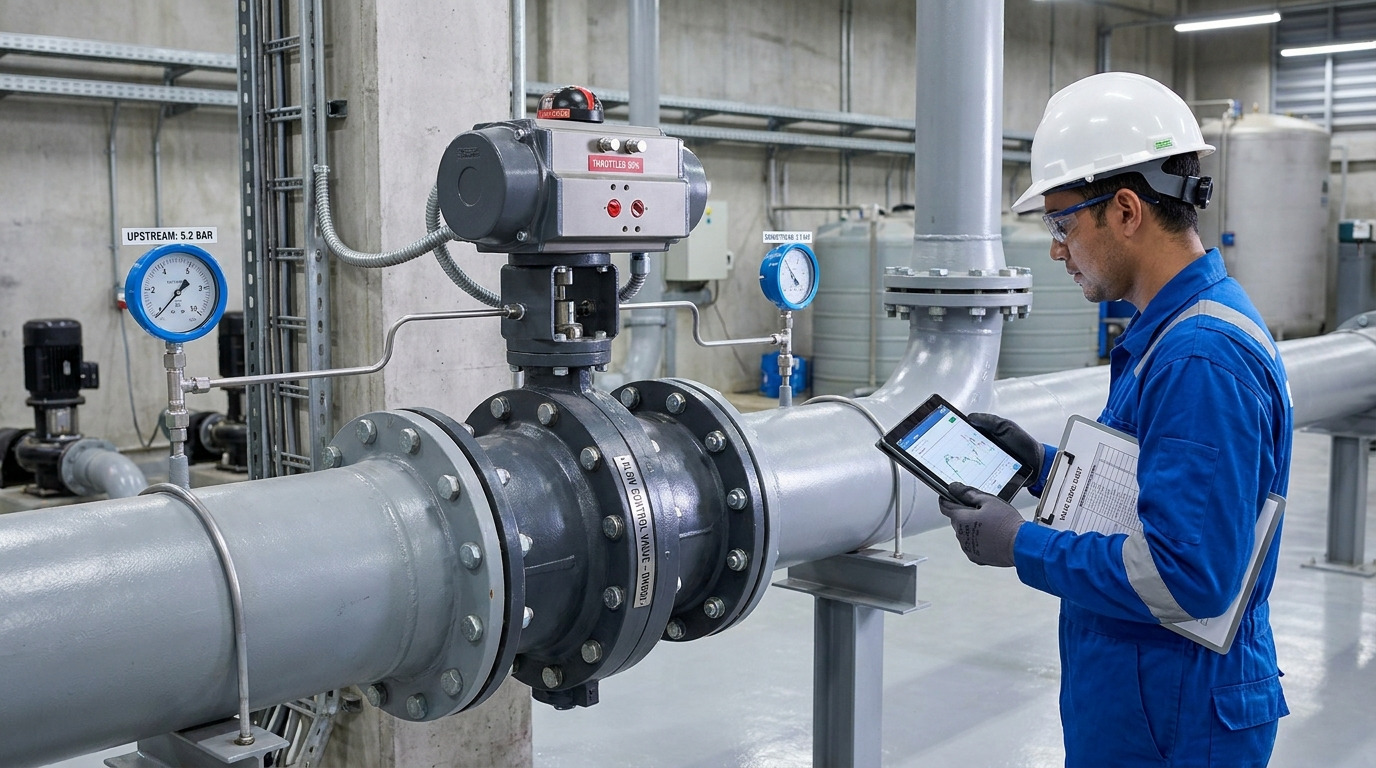
Butterfly valve flow characteristics affect sizing by showing how much capacity the valve delivers at each disc angle, so you can choose a valve that controls in a stable part of its travel instead of only matching pipe size. In practical terms, butterfly valve flow characteristics help you connect three things: percent open, Cv, and the pressure drop available across the valve.
A common problem appears when a line-size valve is automated for throttling and the loop hunts near low opening, then becomes sluggish near high opening. The solution is not simply “use a bigger valve” or “tune the actuator harder.” You need to read the curve, check the system pressure drop, and confirm whether the selected butterfly valve can provide stable control over your real minimum, normal, and maximum flow conditions.
What Butterfly Valve Flow Characteristics Really Mean
Butterfly valve flow characteristics describe how valve opening relates to flow capacity under defined conditions. They do not mean that a valve opened 50 percent will pass exactly 50 percent of the full-open flow.
A butterfly valve is a quarter-turn valve: 0 degrees is closed and 90 degrees is fully open. As the disc rotates, the flow area, turbulence, pressure recovery, and torque all change. Because the disc remains in the flow path even when open, the curve is different from a globe valve plug or a full-port ball valve.
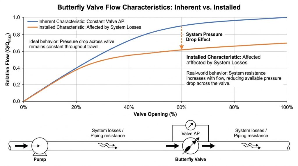
Two curves matter in real sizing. The inherent flow characteristic is the valve curve measured with a constant pressure drop across the valve. The installed flow characteristic is what you get in the actual piping system, where pump head, pipe friction, fittings, strainers, exchangers, and elevation changes all affect the pressure drop available at the valve.
This distinction matters because your control loop responds to installed flow, not catalog theory. A valve that looks smooth on a test curve can behave sharply or weakly after installation if most of the system pressure drop is outside the valve.
Why Disc Angle Changes Flow Nonlinearly
Disc angle changes flow nonlinearly because the valve opening changes both flow area and fluid direction at the same time. That is why a butterfly valve often gives useful throttling in the middle of travel but poor control near the nearly closed or nearly open positions.
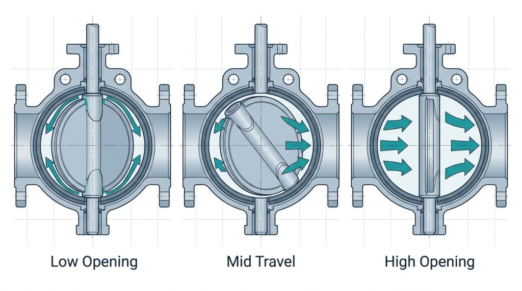
For quick screening, many engineers avoid continuous modulation below about 20 to 30 degrees open and above about 70 to 80 degrees open unless the manufacturer’s curve supports that duty. These are not universal standard limits. They are practical starting points, and the final decision should come from the project Cv curve, torque data, and service conditions. A closer look at butterfly valve flow vs percent open helps you see why percent open alone is not enough.
What happens below 20 to 30 degrees?
Below about 20 to 30 degrees, the opening is narrow and the flow tends to form a high-velocity jet around the disc edge. This can make the controller very sensitive: a small actuator movement may cause a large flow change.
This low-opening region can also increase noise, vibration, cavitation risk in liquids, and seat or disc-edge wear if the valve stays there for long periods. If your normal flow requires the valve to sit near 10 or 15 degrees open, the valve is usually oversized for throttling even if it can pass maximum flow.
What happens above 70 to 80 degrees?
Above about 70 to 80 degrees, additional opening may add little useful flow because the valve is already close to its maximum capacity. The controller can keep asking for more travel while the process flow barely changes.
This is a common reason an automated butterfly valve feels “flat” at high demand. It may still be excellent as an isolation valve, but it has limited remaining control authority in that high-open region.
Why does the installed curve look different?
The installed curve looks different because the valve does not receive a constant pressure drop in the real system. As flow increases, more pressure is consumed by pipe friction and equipment losses, so the valve may receive less differential pressure than the inherent curve assumes.
Valve authority is a useful way to judge this effect. It is commonly expressed as the pressure drop across the control valve at design flow divided by the pressure drop across the controlled branch or system. As a rule of thumb, values below about 0.25 to 0.30 deserve closer review because the system may dominate the valve and distort the control response.
Key takeaway: do not size a butterfly valve from opening percentage alone. Check the installed curve and the pressure drop available across the valve at each operating point.
How Cv Curves Turn Opening Into Flow Capacity
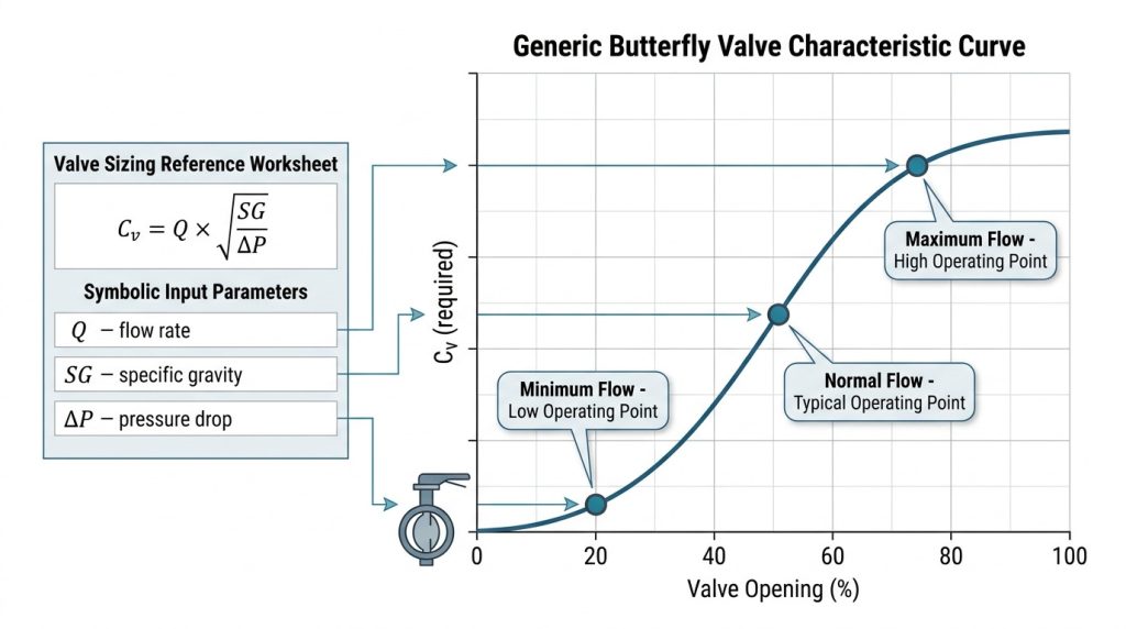
Cv curves turn valve opening into usable capacity data, which lets you compare required flow with the valve’s actual throttling range. Cv is the flow coefficient: in U.S. customary units, it represents the flow of water in gallons per minute at 60°F through a valve with a 1 psi pressure drop.
For clean, turbulent, non-flashing liquid flow, a simplified relationship is:
Q = Cv x sqrt(delta P / SG)
Or, rearranged:
Cv = Q x sqrt(SG / delta P)
Here, Q is flow in gpm, delta P is pressure drop in psi, and SG is specific gravity. For metric work, Kv is often used; a common conversion is Kv = 0.865 x Cv, or Cv = 1.156 x Kv. For gases, steam, flashing liquids, viscous liquids, or two-phase flow, use the appropriate IEC 60534 or ANSI/ISA sizing method instead of this simplified liquid formula.
A verified butterfly valve Cv curve analysis should help you compare the required Cv at minimum, normal, and maximum flow against the valve’s Cv at the corresponding disc angles.
| Sizing item | Practical value or check | Why it matters | Final confirmation |
|---|---|---|---|
| Valve travel | 0 degrees closed, 90 degrees open | Defines the disc angle used on Cv curves | Valve drawing and data sheet |
| Normal control point | Often screened near mid-travel, about 40 to 60 degrees | Leaves room for increasing and decreasing flow | Manufacturer Cv curve |
| Low opening limit | Avoid continuous control below about 20 to 30 degrees unless proven | Reduces hunting, jetting, wear, and cavitation risk | Service-specific sizing review |
| High opening limit | Avoid relying on modulation above about 70 to 80 degrees | Prevents weak response near full open | Installed flow calculation |
| Cv definition | gpm of 60°F water at 1 psi pressure drop | Provides a common capacity basis | ANSI/ISA or IEC sizing basis |
| Valve authority | Review closely below about 0.25 to 0.30 | Low authority can distort control response | Hydraulic calculation |
The table is a screening guide, not a replacement for valve data. Final values depend on valve size, disc design, seat style, shaft geometry, body pattern, actuator resolution, fluid properties, and piping layout.
How do I use Cv without overtrusting it?
Use Cv as a capacity tool, not as a complete performance guarantee. A full-open Cv tells you how much the valve can pass, but it does not prove that the valve will control smoothly at your normal flow.
For example, if water flow is 800 gpm and the available valve pressure drop is 4 psi, the simplified liquid formula gives a required Cv of 400 because 800 divided by the square root of 4 equals 400. You then need to check where Cv 400 falls on the valve’s opening curve. If it occurs near the middle of travel, the valve may be suitable; if it occurs near 10 degrees or 85 degrees, the size or valve type should be reviewed.
When Butterfly Valves Throttle Well
Butterfly valves throttle well when the service accepts moderate control accuracy, the pressure drop is not severe, and the normal operating point falls in the usable middle range of travel. They are especially attractive where compact size, low weight, fast quarter-turn operation, and high flow capacity are important.
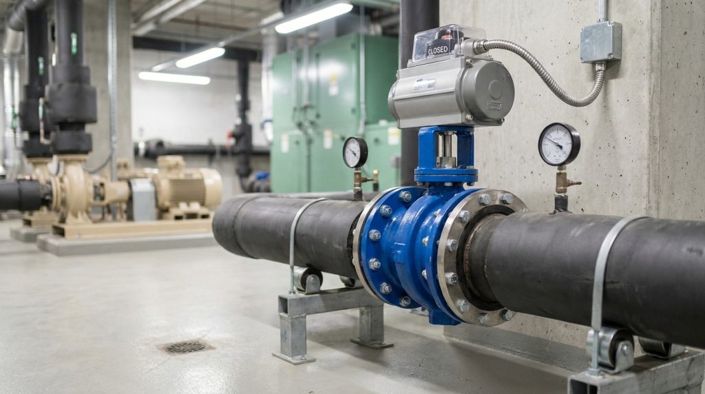
They are often used in water, wastewater, cooling water, HVAC, utility, and many clean process services. For corrosive fluids, abrasive solids, steam, high temperature, or high shutoff requirements, you need to check body material, disc material, seat material, offset design, leakage requirement, and pressure-temperature rating instead of assuming one butterfly valve style fits all services.
What service conditions fit them best?
They fit best in relatively clean fluids where the valve does not need extremely fine low-flow control. Resilient-seated concentric designs are common for water and general utility service, while double-offset or triple-offset designs may be considered for higher temperature, higher pressure, or tighter shutoff requirements.
The control target should be practical. If you need stable adjustment across a wide flow range but not laboratory-level precision, a properly sized butterfly valve can be a strong choice. If you need very fine control near minimum flow, another control valve style may be more suitable.
When should you consider another valve?
Consider another valve when the process requires precise control at very low flow, high pressure drop across the valve, severe cavitation resistance, steam pressure letdown, erosive slurry service, or low-noise gas control. In those cases, a globe control valve, segmented ball valve, or special control valve trim may give better installed performance.
This is not a weakness of butterfly valves. It is a matching issue. Butterfly valves are excellent in the right control envelope, but they should not be forced into duties where the curve, pressure recovery, or seat design works against the process.
Pressure Drop and Cavitation Checks
Pressure drop and cavitation checks decide whether the selected valve can control flow without damaging itself or destabilizing the process. A valve can have the right Cv and still be a poor choice if the pressure drop is too high for its disc, seat, pressure recovery behavior, or actuator torque.
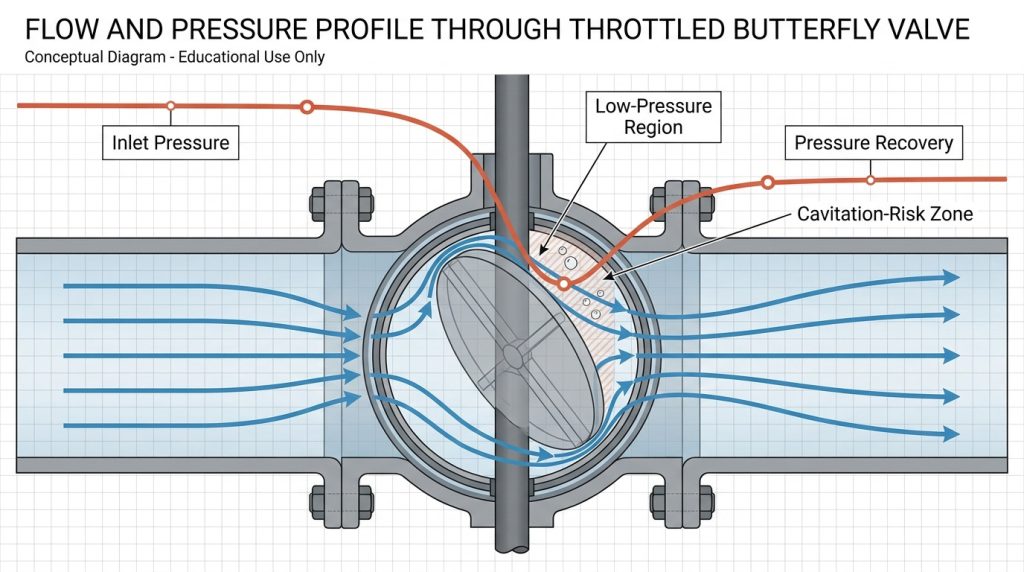
For liquid service, you should check inlet pressure, outlet pressure, temperature, vapor pressure, specific gravity, and the available pressure drop at minimum, normal, and maximum flow. A butterfly valve pressure drop calculation is most useful when it is tied to the actual operating range, not just a full-open loss estimate.
How do I separate Cv from K factor?
Cv describes valve capacity under a defined pressure drop, while K factor is a dimensionless loss coefficient used to estimate pressure loss through a component. Cv is more common for valve sizing and control curves; K factor is often useful when comparing the valve as part of a piping-loss calculation.
You may need both. Cv helps you select the opening and valve size, while butterfly valve K factor helps you understand how the valve contributes to total system resistance. If the K value is used, make sure it corresponds to the valve opening and geometry, not only the fully open position.
What makes cavitation risk higher?
Cavitation risk rises when local pressure near the disc drops below the liquid vapor pressure and then recovers downstream. This risk is higher at small openings, high pressure drops, high velocities, warm liquids, and services where the valve has strong pressure recovery.
Warning signs include noise, vibration, unstable control, pitted metal surfaces, and rapid seat damage. For severe liquid throttling, ask for sizing that considers pressure recovery factors under IEC 60534 or ANSI/ISA control valve methods, and confirm whether the valve style is intended for that duty.
How to Size for Stable Butterfly Valve Control
Stable butterfly valve control starts by sizing from the required flow range and available pressure drop, not from the pipeline nominal diameter. A line-size valve may be correct for isolation but too large for modulation.
A good sizing workflow is simple:
- Define minimum, normal, and maximum flow.
- Confirm fluid, temperature, specific gravity, viscosity, and vapor pressure.
- Calculate available valve pressure drop at each operating point.
- Find the required Cv at each point.
- Compare required Cv with the valve’s Cv curve by opening angle.
- Check actuator torque, seat material, shutoff requirement, and control signal.
- Confirm the final choice with the valve drawing and data sheet.
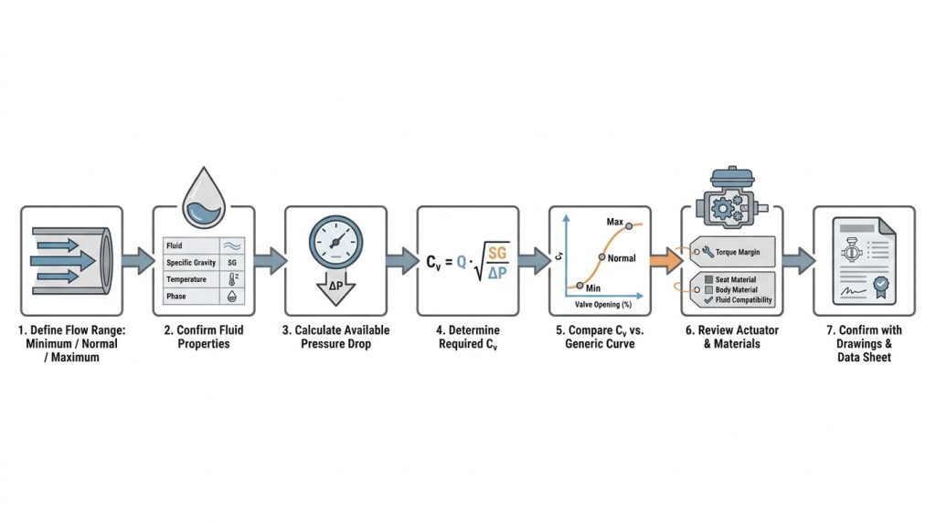
For project-related values, do not stop at “it depends.” Use typical screening ranges such as mid-travel control, low-opening avoidance, and valve authority review, then confirm final values from the manufacturer’s curve and project hydraulic data.
Can a smaller valve improve control?
Yes, a smaller valve can improve control when the original valve is oversized and operates too close to closed at normal flow. Reducing the valve size may move the operating point into a more controllable opening range and increase the pressure drop assigned to the valve.
That choice still needs checks. A smaller valve can increase velocity, pressure drop, noise, cavitation risk, and actuator torque. It can also affect flange transitions, face-to-face dimensions, and maintenance access, so it should be confirmed before purchase.
What should you send for a sizing review?
Send the information that affects the curve, not just the pipe size. Useful data includes fluid name, density or specific gravity, viscosity if relevant, temperature, vapor pressure for liquids, minimum-normal-maximum flow, inlet and outlet pressure, line size, flange standard, body and seat material preference, actuator type, control signal, fail position, and shutoff requirement.
For standards, specify the project basis clearly. Depending on service and region, that may include API 609 for butterfly valve design, ASME B16.5 for flanged connections, ASME B16.34 where pressure-temperature ratings apply, and API 598 or ISO 5208 for pressure testing and seat leakage expectations.
Specification Details That Change the Curve
Specification details change the flow curve because the disc, seat, shaft, body pattern, and actuator all affect how the valve moves and how the fluid passes through it. Two butterfly valves with the same nominal size can behave differently if their internal geometry or seat construction differs.
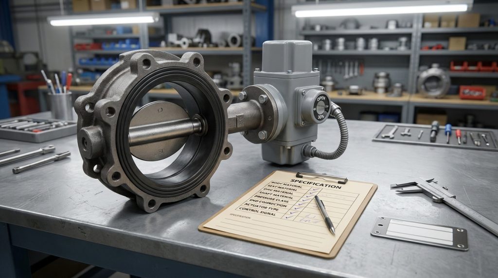
Seat material matters because throttling exposes the seat edge to velocity, heat, and pressure-drop effects. EPDM, NBR, PTFE, and metal seats each have different temperature, chemical, and wear limits. The final selection should be based on the actual medium and the valve data sheet, not on a generic material label.
Actuation also matters. Manual operation may be acceptable for fixed balancing or occasional adjustment, but automated control needs enough torque margin, repeatability, and position feedback. If the actuator resolution is coarse or the linkage has backlash, the installed control may be poor even when the valve body is correctly sized.
What should a data sheet confirm?
A useful data sheet should confirm valve size, pressure class, body material, disc material, shaft material, seat material, end connection, face-to-face standard, Cv or Kv curve, pressure-temperature limits, leakage requirement, actuator torque basis, and operating direction.
For control service, also ask whether the Cv data is full-open only or available by opening angle. Full-open Cv is enough for rough capacity checks, but it is not enough to judge throttling performance across a real operating range.
Common Mistakes in Flow Characteristic Decisions
The most common mistake is treating a butterfly valve as a pipe-size accessory instead of a control element. When the valve modulates, its curve becomes part of the hydraulic design.
Other mistakes are easier to avoid once you know what to look for:
- Selecting by nominal pipe size without calculating required Cv.
- Using full-open Cv while ignoring the Cv curve by disc angle.
- Assuming 50 percent open means 50 percent flow.
- Ignoring installed pressure drop and valve authority.
- Running normal control near the nearly closed position.
- Expecting high precision near full open.
- Adding an actuator without checking dynamic torque.
- Ignoring seat material limits in throttling service.
- Using a butterfly valve for severe cavitation duty without review.
- Comparing valves without confirming the same test basis.
If you avoid these errors, your valve decision becomes much clearer. You are no longer asking only, “Will this valve fit the pipe?” You are asking the more useful question: “Will this valve control the required flow range at stable openings with acceptable pressure drop and service life?”
Conclusion
Butterfly valve flow characteristics matter because they connect disc angle, Cv, pressure drop, and real control behavior. A properly selected butterfly valve can provide efficient throttling in many water, HVAC, utility, and process services, but it should be checked against the installed curve, not just the nominal line size or full-open capacity.
For your next step, gather the flow range, fluid data, inlet and outlet pressures, temperature, connection standard, material requirements, and actuator needs, then send the project conditions for review so the valve size and curve can be discussed against the actual service.
FAQ
Can I use a butterfly valve for throttling instead of a globe valve?
Yes, you can use a butterfly valve for throttling when the service accepts moderate control accuracy and the valve operates in a stable middle range. For very fine low-flow control, severe cavitation, or high pressure-drop service, a globe valve or specialized control valve may be better.
What’s the best opening range for butterfly valve control?
The best practical range is usually the middle of travel, often screened around 30 to 70 degrees open. The exact range depends on valve design, pressure drop, fluid, actuator, and manufacturer Cv data, so final sizing should follow the valve curve.
How do I know if my butterfly valve is oversized?
Your valve is likely oversized if normal flow occurs at a very small opening, such as near 10 to 20 degrees. Other signs include hunting, unstable flow changes, poor actuator response, noise, and excessive sensitivity at low demand.
Can I calculate flow from percent open alone?
No, percent open alone is not enough to calculate flow reliably. You also need the valve Cv or Kv curve, fluid properties, and pressure drop across the valve at that operating point.
What’s the best data to request before ordering?
The best data to request is the Cv or Kv curve by opening angle, not only the full-open value. You should also confirm pressure-temperature rating, seat material limits, leakage requirement, actuator torque, and the standards used for design and testing.