
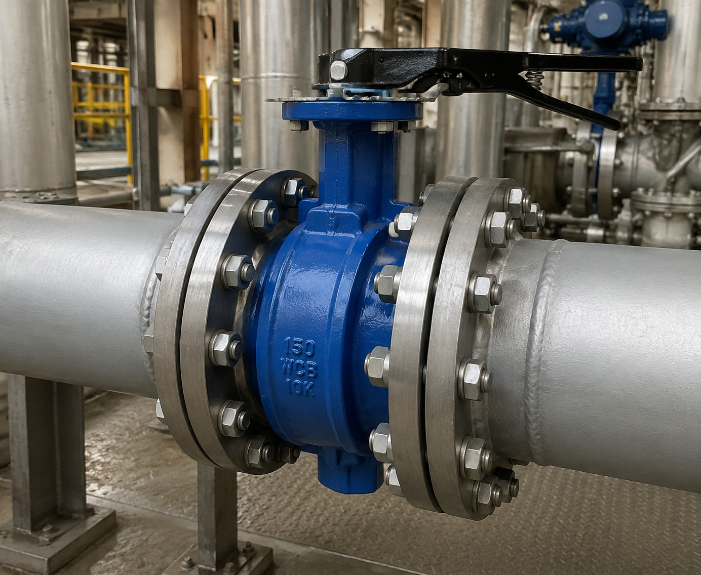
A 150 butterfly valve bolt chart gives the ASME Class 150 flange drilling—bolt count, bolt diameter, bolt-hole size, and bolt circle—but the final fastener length must be checked against the valve body and installed stack. A generic length can leave a wafer-valve stud short of full nut engagement or make a lug-valve cap screw bottom before it clamps the flange.
Use the chart below to confirm the fixed interface first. Then identify the body style, gasket rule, washers, nut arrangement, and tapped-hole depth. That sequence is essential when specifying industrial butterfly valves for new piping or a replacement spool.
What the 150 Butterfly Valve Bolt Chart Actually Fixes
The chart fixes the Class 150 mating-flange geometry; it does not define one universal butterfly-valve bolt length. “Class 150” is a pressure class and dimensional system, not a statement that every valve is rated to exactly 150 psi.
For NPS 24 and below, the controlled basis is the project-specified edition of ASME B16.5. ASME’s standards activity page identifies ASME B16.5-2025 as the current revision for pipe flanges and flanged fittings from NPS 1/2 through NPS 24.
Separate the information into two groups:
- Fixed by the mating flange: NPS, pressure class, bolt quantity, nominal bolt diameter, bolt-hole diameter, and bolt circle.
- Fixed by the valve and joint: fastener type, length, thread series and class, material, washers, gasket allowance, nut arrangement, required engagement, and target preload.
This distinction explains why two Class 150 charts can agree on bolt diameter and quantity yet show different lengths.
Class 150 Flange Drilling Chart, NPS 2–24
This Class 150 reference table answers the first fit-up question: does the valve drilling match the mating flanges? Dimensions are in inches, and bolt quantity is the number of positions in one flange pattern.
| NPS | Bolt quantity | Nominal bolt diameter | Bolt-hole diameter | Bolt circle |
|---|---|---|---|---|
| 2 | 4 | 5/8 | 3/4 | 4.75 |
| 2-1/2 | 4 | 5/8 | 3/4 | 5.50 |
| 3 | 4 | 5/8 | 3/4 | 6.00 |
| 3-1/2 | 8 | 5/8 | 3/4 | 7.00 |
| 4 | 8 | 5/8 | 3/4 | 7.50 |
| 5 | 8 | 3/4 | 7/8 | 8.50 |
| 6 | 8 | 3/4 | 7/8 | 9.50 |
| 8 | 8 | 3/4 | 7/8 | 11.75 |
| 10 | 12 | 7/8 | 1 | 14.25 |
| 12 | 12 | 7/8 | 1 | 17.00 |
| 14 | 12 | 1 | 1-1/8 | 18.75 |
| 16 | 16 | 1 | 1-1/8 | 21.25 |
| 18 | 16 | 1-1/8 | 1-1/4 | 22.75 |
| 20 | 20 | 1-1/8 | 1-1/4 | 25.00 |
| 24 | 20 | 1-1/4 | 1-3/8 | 29.50 |
The decision point is straightforward: use these values to verify the flange pattern, but do not release a bolt length from this table. For NPS above 24, stop and check the applicable large-diameter flange standard and project drawing instead of extending the pattern.
Why Wafer and Lug Valves Need Different Lengths
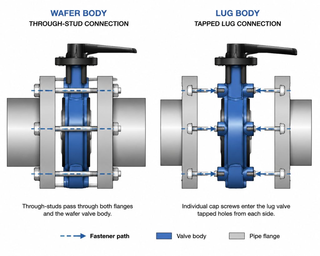
Valve body style changes the fastener path, so it changes both length logic and the main installation risk. A wafer-versus-lug body selection should therefore be settled before the bolt schedule is issued.
Wafer body
A wafer valve is clamped between two pipe flanges. Through-studs normally span both flanges, the valve body at the bolt path, permitted gaskets, washers, nuts, and thread projection. A machine-bolt arrangement uses a head on one end and a nut on the other, so its stack is different from a stud with two nuts.
Lug body
A lug valve normally uses separate cap screws or studs from each side into tapped body lugs. The Class 150 flange pattern may have eight bolt positions, but a complete two-sided lug installation can require sixteen cap screws. Confirm whether each tapped hole is through or blind, the usable thread depth, and whether opposing screws can interfere.
Double-flanged body
A double-flanged valve creates two separate flange joints. Standard flange-joint stud logic is more directly applicable, but the valve’s integral flange thickness, facing, gasket, and drilling must still match the piping specification.
Build Bolt Length From the Installed Stack
The reliable length is the shortest standard fastener that clears the complete stack, achieves the required engagement, and does not bottom or interfere. Do not substitute the valve’s face-to-face dimension for a bolting drawing when body bosses, a seat retainer, or blind holes change the path.
For a wafer through-stud, record both flange thicknesses, valve width at the bolt path, only the gaskets permitted by the valve design, washer thickness, two nut heights, and the specified thread projection beyond each nut. For a machine bolt, replace one nut and its projection with the bolt-head arrangement required by the project.
For a lug cap screw, record one flange thickness, permitted gasket allowance, washer thickness, and required effective engagement in the lug. Then compare that result with the measured usable tapped depth. If the selected screw reaches the bottom before the flange is clamped, length is wrong even when the nominal thread matches.
The thread callout also requires confirmation. ASME B1.1 defines unified inch thread forms, series, classes, allowances, tolerances, and designations; the valve drawing and project fastener specification must state which callout applies.
NPS 8 shows why the drawing wins
The fixed NPS 8 Class 150 pattern is eight 3/4-inch fastener positions on an 11.75-inch bolt circle with 7/8-inch holes. Typical valve guides, however, may place a wafer machine bolt near 6 inches, a wafer stud around 6-3/4 to 7 inches, and a lug cap screw around 2-1/4 to 2-1/2 inches.
Those figures are preliminary examples, not universal dimensions. The detailed NPS 8 body-style example shows why washer use, flange facing, valve series, and tapped depth can move the result.
Validate the Chart Before Releasing the Order
Release bolting only after three documents agree: the flange standard, the valve manufacturer’s dimensional or bolting drawing, and the project piping or fastener specification. If they conflict, the generic online chart is the first item to discard.
Use this evidence order:
- Confirm NPS, Class 150, flange type, and facing from the line class, isometric, flange markings, or controlled drawing.
- Confirm wafer, lug, or double-flanged construction from the exact valve model and approved drawing.
- Confirm bolt-path width, tapped-hole type and depth, gasket rule, washer use, nut style, thread callout, and material from the valve and project documents.
- Compare the calculated stack with the manufacturer’s recommended length, then select an available standard length without reducing engagement or causing bottoming.
- Record the chosen fastener and drawing revision in the purchase order or installation work pack.
This process closes a common execution gap: a chart may be technically correct for its assumed valve series but wrong for the valve delivered to your site.
Install and Tighten Without Distorting the Valve
Correct bolting will not rescue a misaligned or over-compressed valve. Before tightening, support the piping, clean and parallel the flange faces, center the valve without using bolts to pull the line into place, and verify disc-to-pipe clearance.
Follow the exact valve manual on disc position and gasket use. Many resilient-seated designs use the seat face as the flange seal and prohibit extra gaskets; other high-performance designs require a specified gasket. Review butterfly valve gasket selection before adding thickness to the joint.
Bring all fasteners snug, recheck centering, and tighten in the specified cross pattern through progressive passes. Do not copy a torque value from a diameter-only chart: achieved preload changes with fastener material, thread condition, lubricant, nut and washer combination, gasket or seat design, and project procedure.
Where its stated gasket scope matches the joint, ASME PCC-1 provides guidance for pressure-boundary bolted flange assembly. A resilient seat that seals directly against the flange face may not match that ring-gasket scope, so the valve manual remains controlling. After snugging, use the permitted alignment and disc-clearance checks before final tightening and pressure testing.
Release Checklist for Procurement and Site Teams
A complete bolt release identifies the joint, the fastener, and the verification basis. Send the following information with an RFQ, purchase order, or field request:
- Valve tag, exact model, NPS, and quantity
- ASME Class 150 flange standard, facing, and pipe-flange type
- Wafer, lug, or double-flanged body style
- Approved valve drawing and revision
- Bolt or stud type, diameter, thread callout, and selected length
- Fastener material, coating, nut grade, and washer requirement
- Separate-gasket rule and thickness, if permitted
- Lug-hole condition: through or blind, usable depth, and required engagement
- Tightening procedure and target value source
- Final checks for centering, free disc travel, thread projection, and no bottoming
The release is incomplete if it says only “Class 150 butterfly valve bolts.” That phrase defines neither the body path nor the conditions that determine length and preload.
Make the Chart a Controlled Fit-Up Check
A 150 butterfly valve bolt chart is reliable when you use it to verify Class 150 drilling and pair it with the exact valve drawing. Keep flange geometry, body-style length, thread specification, gasket rule, and tightening procedure as separate decisions, then document the result before fasteners reach the site.
RUITO supplies wafer, lug, and flanged butterfly-valve configurations and can provide dimensional drawings and order documentation for joint review. To confirm a project-specific bolt schedule, send your flange and valve details to our engineering team, including the model, NPS, flange facing, gasket rule, and planned fastener arrangement.
FAQ
Does Class 150 mean the valve is rated for only 150 psi?
No. Class 150 is a pressure-temperature class and dimensional designation. The allowable pressure depends on the valve design, body and seat materials, temperature, applicable standard, and manufacturer rating.
Can I use a Class 150 chart for a DN200 PN16 valve?
No. ASME Class 150 and EN PN16 drilling are not automatically interchangeable. Confirm the bolt quantity, hole size, bolt circle, and fastener system from the actual flange standard even when NPS 8 and DN200 are treated as nominal equivalents.
Do washers simply add their thickness to the bolt length?
They add stack thickness, but that is not the only check. Washers can also change available thread projection, wrench clearance, and a lug screw’s margin before bottoming, so use the washer specified by the joint procedure and recalculate the complete stack.
Can existing bolts be reused during valve replacement?
Only when the project procedure permits reuse and inspection confirms the correct grade, thread, length, coating, and undamaged condition. Replace fasteners that are corroded, stretched, galled, cross-threaded, or of uncertain origin.