
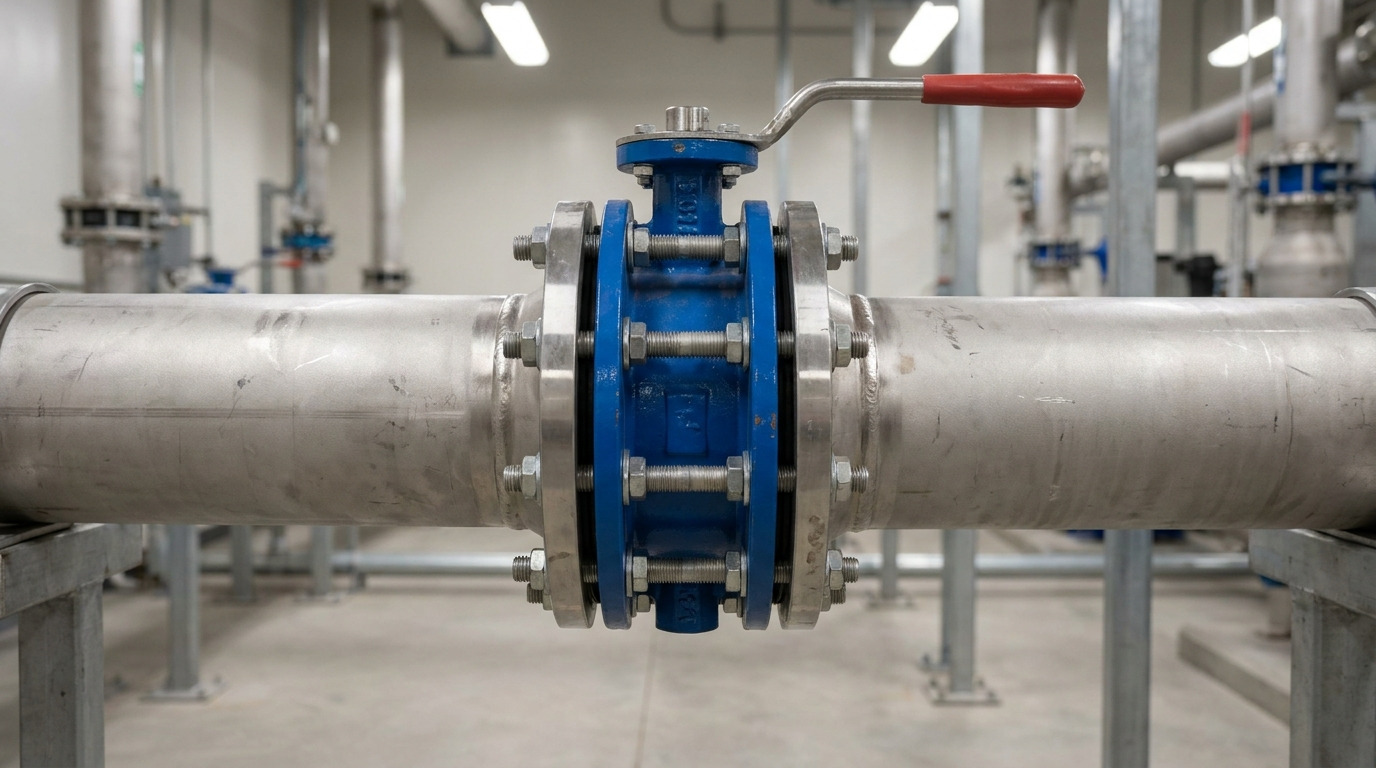
A butterfly wafer valve works well when the piping flanges can clamp the valve evenly, the disc has enough clearance to rotate, and the seat material matches the pressure, temperature, and fluid. The butterfly wafer valve is mainly a compact quarter-turn isolation valve, so it is strongest in clean water, HVAC, utility, and many process lines where low weight, short face-to-face length, and fast operation matter.
If you are comparing a wafer design with other butterfly valve options, the key question is not only “Does it fit between the flanges?” You also need to know whether it can seal under your differential pressure, whether the line can be safely depressurized for maintenance, and whether the valve is being used for shutoff, limited throttling, or both.
What Is a Butterfly Wafer Valve?
A butterfly wafer valve is a thin-body butterfly valve installed between two pipe flanges and held in place by flange bolts or studs. It has no full external flange of its own; instead, the pipeline flanges compress the valve body and seat to create the sealing interface.
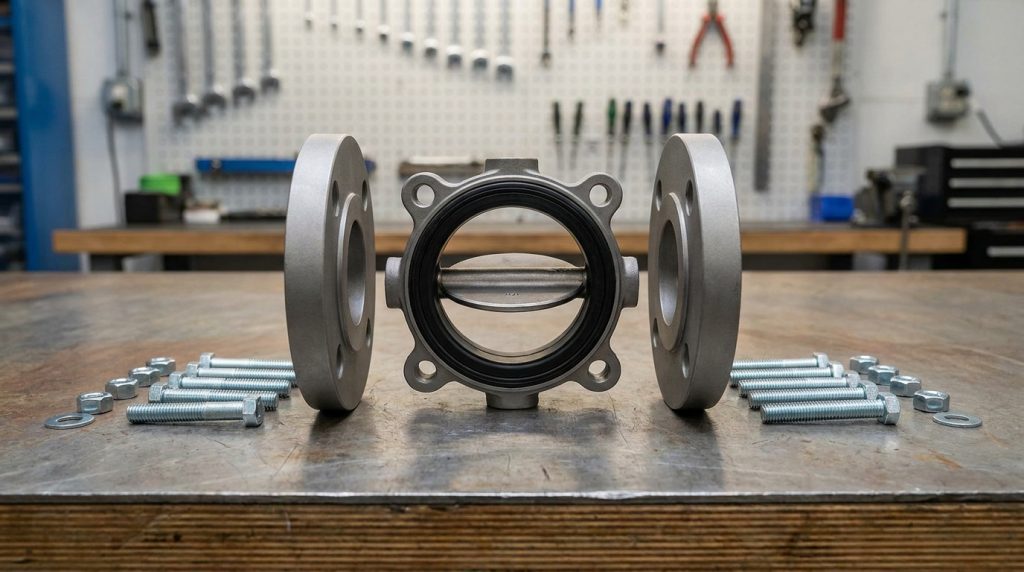
This design saves space and weight compared with many flanged valves. The tradeoff is that the valve depends heavily on correct flange alignment, bolt loading, gasket or seat contact, and disc clearance inside the pipe bore.
Why is the wafer body so compact?
The wafer body is compact because it does not need long end connections, heavy flanges, or a bolted bonnet. The pressure boundary is concentrated around the valve body, while the pipeline flanges supply the clamping force.
That compact shape is useful in crowded pump rooms, treatment skids, HVAC headers, and utility manifolds. It also means the valve is less forgiving of misaligned flanges than a heavier double-flanged design.
What parts should you recognize?
The main parts are the body, disc, stem or shaft, seat or liner, stem seals, bearing surfaces, and manual or actuated operator. In soft-seated designs, the elastomer or polymer seat normally provides both line sealing and flange-face sealing.
The disc is the flow-control element. When it is parallel to the flow path, the valve is open; when it is across the flow path, it is closed.
How a Butterfly Wafer Valve Works
A butterfly wafer valve works by rotating a central disc through about 90 degrees between open and closed positions. This quarter-turn motion makes the valve quick to operate, simple to automate, and easy to identify visually when a handle or position indicator is fitted.
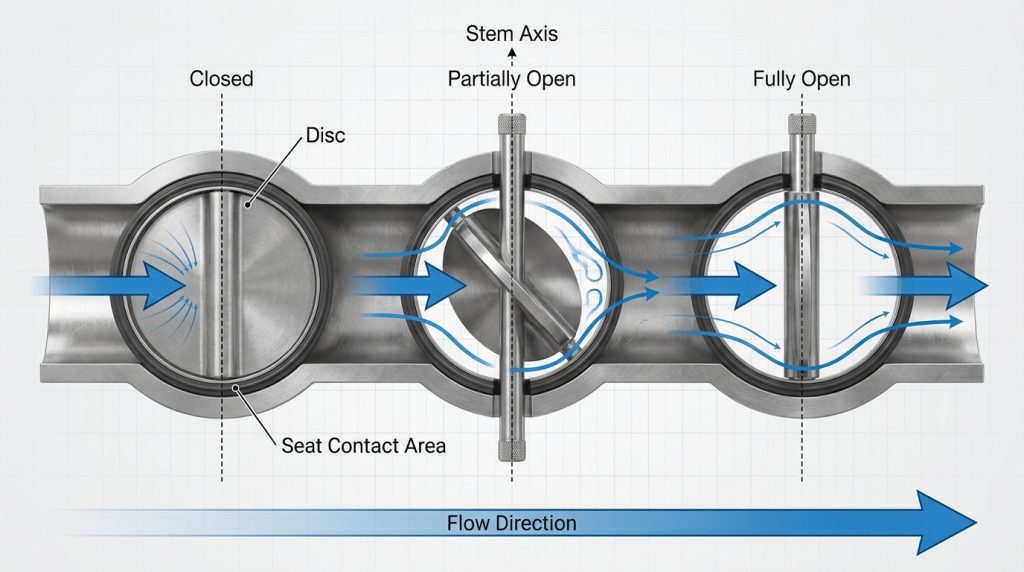
The working principle is simple, but the sealing behavior is not only about the disc. The seat, stem alignment, flange compression, pressure direction, and operating torque all affect whether the valve closes reliably.
What happens during opening and closing?
At 0 degrees open, the disc presses into the seat and blocks the flow path. As the stem turns, the disc moves away from the seat and allows fluid to pass around both sides of the disc.
At 90 degrees open, the disc is aligned with the flow direction. There is still some pressure loss because the disc and shaft remain inside the pipeline, so a butterfly valve is not a full-bore valve in the same way as a full-port ball valve.
Why does seat compression matter?
Seat compression matters because a soft-seated wafer valve often seals at two places: around the disc and against the flange faces. Too little compression can cause leakage; too much compression can increase torque, distort the liner, or make the disc drag.
This is why flange flatness, bolt tightening sequence, and correct gasket practice matter more with wafer valves than many buyers expect. If you want a deeper check before installation, review the valve’s flange fit, disc clearance, and bolt path against the practical risks covered in butterfly wafer valve fit and installation risks.
Where a Wafer Design Fits Best
A wafer design fits best where compact isolation is needed, both sides of the line normally remain connected, and the valve is not expected to support dead-end service by itself. It is common in water systems, cooling loops, general utilities, non-abrasive process fluids, and many moderate-pressure lines.
For example, wafer butterfly valves are often a practical fit in water and wastewater treatment systems because many lines need frequent isolation, compact installation, and economical large-diameter flow control. The same logic can apply to HVAC and utility water, provided the materials and pressure rating match the duty.
The table below helps you separate good-fit conditions from cases that need more caution.
| Decision Point | Wafer Valve Usually Works Well When | Use Caution When |
|---|---|---|
| Operation type | On-off isolation or limited throttling is needed with 0 to 90 degree quarter-turn motion | Tight modulating control is required across the full travel range |
| Flange standard | The valve is ordered for the same flange drilling and bore system as the pipeline, such as ASME B16.5-2025 for NPS 1/2 to NPS 24 flanges or ASME B16.47-2025 for NPS 26 to NPS 60 flanges | The pipe uses mixed standards, old flanges, nonstandard bore, or uncertain bolt-circle dimensions |
| Throttling position | The valve normally operates in a moderate opening band; many manufacturer data sheets treat roughly 30 to 70 degrees open as a more stable throttling zone | The valve is held near closed for long periods, where velocity, noise, cavitation, and seat erosion risks increase |
| Maintenance isolation | Both upstream and downstream piping can be depressurized before removal | One side of the pipeline may stay pressurized during maintenance |
| Factory testing | The purchase order clearly states the required test standard, such as API 598 for valve inspection and pressure testing | The order only says “standard test” without defining shell, closure, or leakage expectations |
The main conclusion is practical: a wafer valve is not weak just because it is compact, but it must be matched to the piping standard, pressure class, media, and maintenance method.
Wafer vs Lug and Flanged Designs
The main difference is how the valve is supported and bolted into the pipeline. A wafer valve is clamped between flanges, a lug valve has threaded or through-lug body holes, and a double-flanged valve has its own flanges.
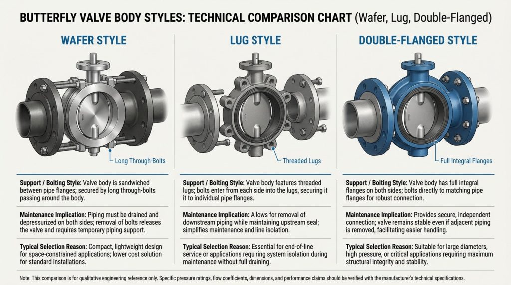
This difference affects maintenance, dead-end service, pipe loading, and replacement work. If you are deciding between wafer and lug bodies for a real line layout, the comparison in wafer vs lug style butterfly valve is the most relevant next step.
Can a wafer valve handle dead-end service?
A standard wafer valve is usually not the first choice for dead-end service unless the manufacturer specifically rates it for that condition. Because the body is clamped between two flanges, removing one side of the pipe can remove part of the support and sealing force.
If one side of the line may remain pressurized during maintenance, a lug-style or flanged design is often safer to evaluate. Always confirm the rated dead-end pressure, flow direction limits, and bolting arrangement on the valve data sheet.
When is a lug or flanged valve better?
A lug valve is better when downstream piping may need to be removed while the upstream side remains in place, provided the valve is rated for that use. A flanged butterfly valve is better when the line size is large, pipe loads are higher, or the project specification requires bolted flanged ends.
A wafer valve is better when the system needs a lighter, shorter, more economical valve and normal maintenance allows full line depressurization. That makes it attractive, but not universal.
Materials Seats and Service Limits
Material selection decides whether the wafer valve can seal, resist corrosion, and operate without excessive torque. The body, disc, stem, and seat must be chosen as a set, not as separate catalog items.
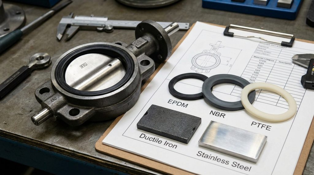
Common body materials include cast iron, ductile iron, carbon steel, stainless steel, and special alloys. Common seat materials include EPDM, NBR, PTFE, and other elastomers or polymers, each with different limits for temperature, chemicals, abrasion, and pressure cycling.
How do seat materials change the decision?
Seat material changes the valve’s real service boundary more than many buyers expect. EPDM is often used for water and many low-temperature utility fluids, NBR is often considered for oil-compatible service, and PTFE is often selected where chemical resistance or higher temperature capability is more important.
Do not treat these as universal rules. Final seat selection should be checked against the actual medium, concentration, temperature, cleaning fluid, and pressure cycle shown on the valve data sheet.
What body and disc materials matter most?
Body material mainly affects pressure boundary strength, corrosion resistance, cost, and flange compatibility. Disc material affects flow exposure, corrosion resistance, sealing surface durability, and torque.
For clean water service, ductile iron bodies with coated or stainless discs may be practical. For corrosive media, stainless steel or lined designs may be needed, and the seat material often becomes the limiting factor before the metal body does.
What to Verify Before Ordering One
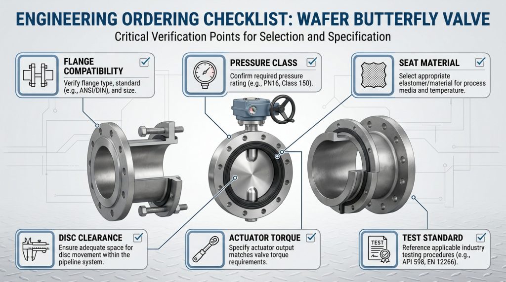
The most important checks before ordering are flange match, valve size, pressure class, seat material, disc clearance, operator torque, and test requirements. If any one of these is assumed instead of confirmed, the valve may fit on paper but fail during installation or operation.
A useful wafer valve specification should include the valve size, flange standard, pressure rating, body material, disc material, stem material, seat material, operator type, test standard, and whether the valve is for isolation or throttling. For actuated valves, also confirm supply voltage or air pressure, fail position, control signal, enclosure rating, and actuator mounting interface.
How do I confirm flange compatibility?
Confirm the flange standard, nominal size, pressure class, bolt circle, flange bore, and sealing face before ordering. ASME B16.5-2025 covers NPS 1/2 through NPS 24 flanges, while ASME B16.47-2025 covers NPS 26 through NPS 60 large-diameter steel flanges.
If the project uses EN, DIN, JIS, or mixed-site flanges, do not assume an ASME-pattern wafer valve will fit. The valve drawing should be checked against the actual pipe flange drawing, especially for disc swing clearance.
What test language belongs in the specification?
The test language should name the inspection standard and the expected closure test. API 598 is commonly used for valve inspection and testing, and for API 609 Category A butterfly valves it includes shell test pressure based on 1.5 times the maximum cold working pressure.
Low-pressure closure testing under API 598 is commonly specified at 80 plus or minus 20 psig. High-pressure closure requirements depend on valve type and purchase specification, so the order should not simply say “tested before shipment” if leakage acceptance matters.
When does actuation become important?
Actuation becomes important when the valve is large, frequent operation is expected, the line is remote, or the system needs control feedback. Manual handles are simple for smaller valves, gear operators reduce handwheel effort, and pneumatic or electric actuators support automation.
For actuator mounting, ISO 5211:2026 defines part-turn valve actuator attachment dimensions. Still, the mounting pad standard does not prove the actuator is correctly sized; torque must be checked against pressure differential, seat material, media condition, and safety factor.
Common Mistakes That Reduce Reliability
Most wafer valve problems come from treating the valve as a simple spacer instead of a pressure-containing sealing component. The valve may be compact, but it still needs correct alignment, bolt loading, material selection, and test definition.
The most common mistakes are avoidable:
- Ordering by nominal pipe size only, without checking flange drilling and pressure class
- Assuming wafer and lug valves have the same maintenance behavior
- Using a soft seat that is not compatible with the actual chemical or cleaning fluid
- Installing the valve where the disc hits the pipe, flange, or nearby fitting
- Holding the disc nearly closed for throttling and creating noise, vibration, or seat erosion
- Adding an actuator without checking seating torque and maximum differential pressure
- Forgetting to define API 598, API 609, or project-specific leakage requirements in the purchase order
Key Takeaway: a wafer valve is usually economical because the body is compact, not because the specification can be vague. The more clearly you define flange fit, material, service condition, and test expectations, the more reliable the final valve choice becomes.
Conclusion
A butterfly wafer valve is a compact, fast-operating valve that works best in lines where the flanges can clamp the body evenly, the disc has proper clearance, and the seat material matches the fluid, pressure, and temperature. The strongest decisions come from checking the practical boundaries: wafer versus lug behavior, flange standard, dead-end limits, throttling range, material compatibility, and factory test language.
If you are reviewing a wafer butterfly valve for a project, prepare the line size, flange standard, pressure class, medium, temperature, seat preference, actuator requirement, and any API 598 or API 609 test expectations, then send your valve requirements so they can be reviewed against the actual service conditions.
FAQ
Can I use a butterfly wafer valve for throttling?
Yes, but only within a realistic control range and with the correct valve data. Many butterfly valve data sheets treat the mid-travel range, often around 30 to 70 degrees open, as more stable for throttling; near-closed positions can increase velocity, noise, cavitation, and seat wear.
What’s the best seat material for a wafer butterfly valve?
The best seat material is the one that matches the medium, temperature, pressure, and cleaning conditions. EPDM is common in many water services, NBR is often considered where oil compatibility matters, and PTFE is useful for broader chemical resistance, but the final limit must come from the selected valve data sheet.
How do I know if wafer or lug style is better?
Choose wafer style when compact installation and normal full-line depressurization are acceptable. Choose lug style when the piping arrangement may require one side of the line to be removed or isolated differently, provided the lug valve is rated for that condition.
Can I install a wafer butterfly valve between any flanges?
No, you should not assume that. The valve must match the flange standard, pressure class, bolt circle, sealing face, and pipe bore, and the disc must have enough clearance to rotate without touching the pipe or flange.
What should I include in a wafer valve inquiry?
Include nominal size, flange standard, pressure class, body and seat material preference, fluid, temperature, operating pressure, shutoff or throttling duty, actuator type, and required test standard. Those details help confirm whether the wafer design is suitable before drawings or purchase specifications are finalized.