
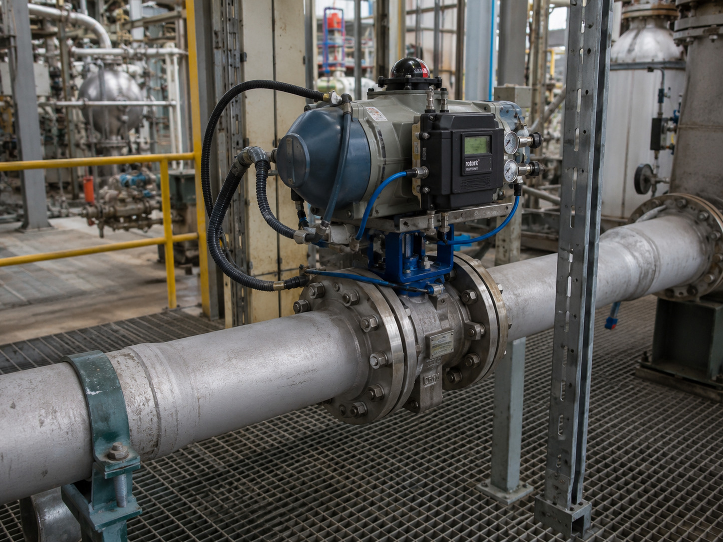
A throttle butterfly valve can control an industrial pipeline reliably when its size, disc characteristic, available pressure drop, cavitation margin, and actuator response keep the real operating points inside a stable modulating range. It is not enough for the valve to pass design flow or rotate to a commanded angle.
The phrase can also describe an automotive throttle plate or a vacuum conductance valve. This article addresses butterfly valves used to regulate liquids or gases in industrial piping. In that setting, the usual failure is a line-size valve that passes maximum flow easily but spends normal operation near one end of its travel, where small movements either change flow too sharply or accomplish almost nothing.
RUITO supplies industrial butterfly valve configurations for isolation and control duties. Before selecting one for throttling, you need to separate what the valve can do mechanically from what the complete piping and control system will do after installation.
What a Throttle Butterfly Valve Actually Controls
A throttle butterfly valve changes flow resistance by rotating a disc through the pipe bore. With the disc closer to the flow direction, capacity rises; as the disc turns across the bore, the restriction and pressure drop increase.
That simple movement does not produce a simple percentage relationship. Fifty percent travel is not necessarily fifty percent flow, because disc geometry changes both the open area and the direction of the fluid. The result also depends on the pressure available across the valve at that moment.
In a closed loop, the valve is only the final control element. A flow, pressure, level, or temperature controller moves the actuator, while the pump, piping, equipment, and process demand determine the installed result. For this reason, a useful definition is: a throttle butterfly valve is a rotary final control element whose disc position varies the installed flow resistance of a piping system.
The Operating Envelope That Makes Throttling Work
Reliable throttling requires a usable span of travel in which each actuator movement creates a predictable process change without excessive velocity, wear, or loss of control authority. The exact angles must come from the selected valve’s travel-versus-Cv or travel-versus-Kv data; a universal angle rule cannot approve every disc design and service.
The inherent curve is measured under defined test conditions. The installed curve changes as pipe friction, heat exchangers, filters, pumps, and other restrictions consume a changing share of system pressure. The International Society of Automation’s explanation of installed flow characteristics shows why a falling valve pressure drop as flow rises can reshape the response seen by the controller.
This distinction separates three different duties:
| Duty | What may be acceptable | What must be verified |
|---|---|---|
| Occasional balancing | Manual or geared positioning at a fixed setting | Lockable position, capacity at that setting, allowable noise and vibration |
| Continuous modulation | Automated movement through a repeatable working window | Installed curve, minimum/normal/maximum points, actuator resolution and duty cycle |
| Severe pressure reduction | A purpose-designed control solution | Cavitation or choking limits, noise, trim protection, and whether another valve type is safer |
The key decision is therefore not “Can a butterfly valve throttle?” It is “Can this valve control all required operating points without being forced into an unstable or damaging part of its envelope?”
Size the Valve Around Three Operating Points
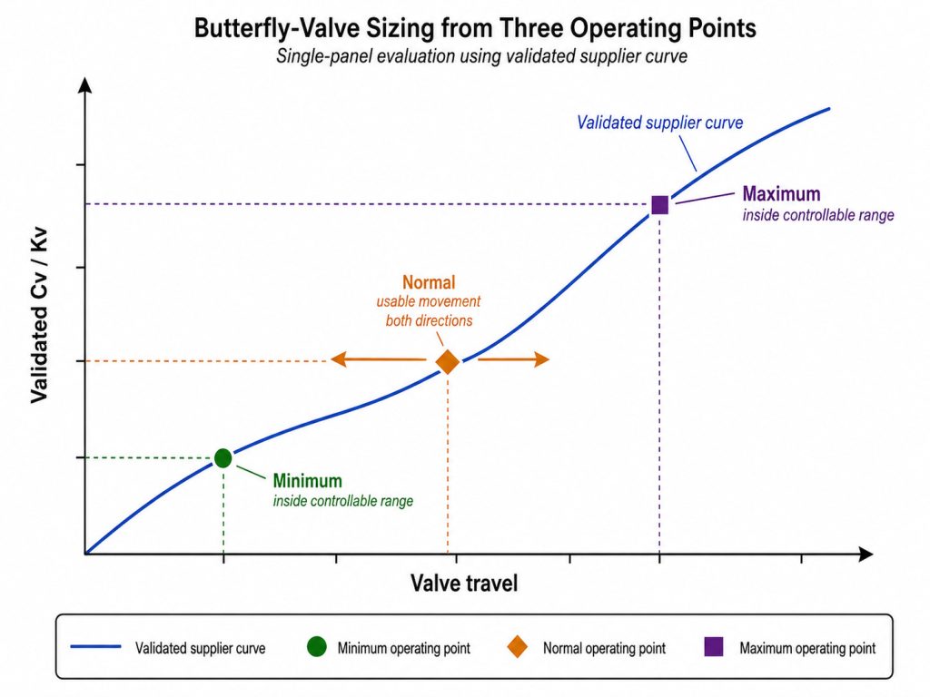
Size the valve by minimum, normal, and maximum demand rather than by nominal pipe diameter alone. A valve can match the line and still be oversized for control, especially when the process normally runs far below design capacity.
Build the Operating Data Set
For each operating point, record:
- Required flow and control variable, such as downstream pressure or tank level
- Upstream and downstream absolute pressure
- Fluid, temperature, density or specific gravity, viscosity, and vapor pressure for liquids
- Pipe size, pump or compressor condition, and major system pressure losses
- Allowed pressure drop, noise limit, leakage class, and fail position
- Valve Cv or Kv by travel, not only the fully open coefficient
If gas density changes materially or the pressure ratio can approach choking, include compressible-flow conditions. If solids are present, describe particle size, concentration, and whether settling can expose the seat or disc edge to a concentrated jet.
Plot the Points Before Choosing the Nominal Size
Calculate the required coefficient at all three points with the appropriate liquid or gas sizing method, then plot each result on the candidate valve’s coefficient curve. The normal point should retain useful movement in both directions, while the minimum and maximum points should remain controllable with margin for process variation.
Do not substitute a fully open catalog Cv for this exercise. If you need to check how coefficient and opening affect hydraulic loss, use the butterfly valve pressure-drop calculation as a starting worksheet, then confirm the result against the selected valve data and the complete system model.
Screen Cavitation, Noise, and Erosion Before Approval
Approve liquid throttling only after checking whether local pressure at the restriction can fall to the fluid’s vapor pressure and whether the valve can recover pressure without damaging bubble collapse. Design pressure drop alone does not answer that question.
Inside a partly open butterfly valve, flow accelerates around the disc edge and the local static pressure falls. If vapor bubbles form and then collapse as pressure recovers downstream, cavitation can pit the disc, seat area, and body while producing noise and vibration. The ISA review of cavitation in butterfly control valves explains why pressure recovery and the valve’s recovery factor matter, not merely inlet and outlet pressure.
For a liquid service, require inlet pressure, outlet pressure, operating temperature, vapor pressure, and the applicable recovery or cavitation data at the intended travel. For a gas service, screen for choked flow, aerodynamic noise, outlet velocity, and vibration. For abrasive liquid or slurry, evaluate where the throttling jet strikes; a material that survives fully open isolation duty may erode rapidly when the disc holds that jet in one location.
Red flags include crackling noise, a sudden change in vibration, unstable downstream pressure, rapid seat leakage, or a controller that repeatedly drives the valve close to one travel limit. These signals call for a new hydraulic review, not just tighter controller tuning.
Choose the Disc, Seat, and Duty Together
Disc offset and seat design change sealing friction and wear, but they do not by themselves guarantee good throttling. Flow characteristic, pressure recovery, materials, actuator behavior, and installed conditions remain decisive.
| Configuration | Reasonable throttling role | Main caution |
|---|---|---|
| Concentric, resilient seated | Occasional balancing or moderate control in compatible, lower-severity service | Continuous operation near closed can concentrate velocity at the liner and disc edge |
| Double offset | Modulating duty where reduced seat rubbing and improved cycling are important | Offset does not replace angle-specific coefficient and cavitation data |
| Triple offset, metal seated | Higher-temperature or metal-seat service that also requires isolation | Tight shutoff and high-temperature capability do not automatically provide fine low-flow control |
Select every wetted part against the actual medium. RUITO’s published butterfly-valve options include ductile iron, carbon steel, stainless steel, duplex, coated and alloy disc choices, plus EPDM, NBR, PTFE, FKM, and metal seating. The final pressure-temperature envelope is set by the complete material combination, not the body rating alone.
For clean and treated water, seat compatibility, disinfectants, suspended solids, and required approvals still need separate confirmation; our water and wastewater valve application guidance provides the broader service context. When the process needs precise low-flow regulation, large pressure reduction, or better resistance to severe cavitation, compare a purpose-designed globe valve option rather than forcing a butterfly valve into the duty.
Treat the Actuator as Part of the Control Valve
An automated butterfly valve controls only as well as its actuator, coupling, positioner, feedback, and accessories allow. Adequate break torque for shutoff does not prove that the assembly can make small, repeatable movements while flow torque changes across the stroke.
Specify torque at the worst differential pressure, required safety margin, travel time, fail action, cycling rate, environmental protection, and position feedback. For pneumatic assemblies, state supply-pressure limits; for electric units, state power, control signal, duty rating, and the response required after loss of power or signal.
Resolution, deadband, backlash, and step response matter when the process needs continuous control. ISA-TR75.25.02-2024 treats the control valve as the complete body, actuator, motion-conversion mechanism, and required accessories. Apply the same boundary during factory acceptance and commissioning: command small steps in both directions, record requested and actual position, and confirm that the process response does not stall, jump, or reverse unpredictably.
Turn the Decision Into an RFQ Acceptance Package
A usable RFQ converts “suitable for throttling” into data the supplier must submit and performance the assembled valve must demonstrate. Include the following items:
- Minimum, normal, and maximum operating cases with pressures, temperatures, and fluid properties
- Selected valve size, connection, offset type, body, disc, stem, seat, and packing materials
- Cv or Kv versus travel, with all three operating points marked on the proposed curve
- Cavitation, choking, velocity, and noise review where the service can trigger them
- Actuator sizing basis, fail action, positioner or controller details, feedback, and expected response
- Design, face-to-face, flange, leakage, inspection, and testing requirements
- Material certificates, dimensional report, pressure-test record, torque or operation record, and final tag traceability
RUITO’s current butterfly-valve range lists DN25–DN3000 and PN10–PN25 configurations, subject to design and material limits. The same page lists wafer, lug, and flanged bodies; EN 593, API 609, MSS SP-67, AWWA C504, and BS 5155 design options; and EN 12266-1, API 598, and ISO 5208 testing options. Your purchase specification should name the exact standards and acceptance criteria required for the project rather than treating this list as interchangeable.
For control duty, ask for the curve and analysis before order release. At inspection, link material and test records to the valve tag or serial identity so the approved design can be traced to the delivered assembly.
Make the Valve Prove Its Control Window
The correct throttle butterfly valve is the one that controls all required operating points, survives the local fluid effects, and responds predictably as a complete actuated assembly. Start with the installed duty, verify the curve and risk limits, then make the evidence part of the RFQ and acceptance plan. RUITO can review your service data, proposed standards, materials, actuator, and documentation package; send us your three operating points to begin a technical review or quotation.
FAQ
Can one butterfly valve provide both modulation and tight shutoff?
Yes, but both duties must be specified and verified separately. The seat and offset may support the required leakage performance, while the coefficient curve, cavitation limits, and actuator response must independently prove modulation.
Is a double-offset valve automatically better for throttling?
No. Double offset can reduce seat rubbing and improve cycling, but it does not guarantee a suitable installed characteristic or adequate cavitation margin. Compare angle-specific flow data under the real operating cases.
Can a manual butterfly valve be used for balancing?
Yes, for an occasional or fixed balancing setting when the position can be locked and the resulting pressure drop, noise, and vibration are acceptable. It is not a substitute for automated closed-loop control when demand changes continuously.
What is the clearest proof that the valve is not oversized?
The clearest proof is a coefficient-versus-travel curve with minimum, normal, and maximum required points plotted on it. The normal point should leave useful controllable movement on both sides instead of sitting close to closed or fully open.