
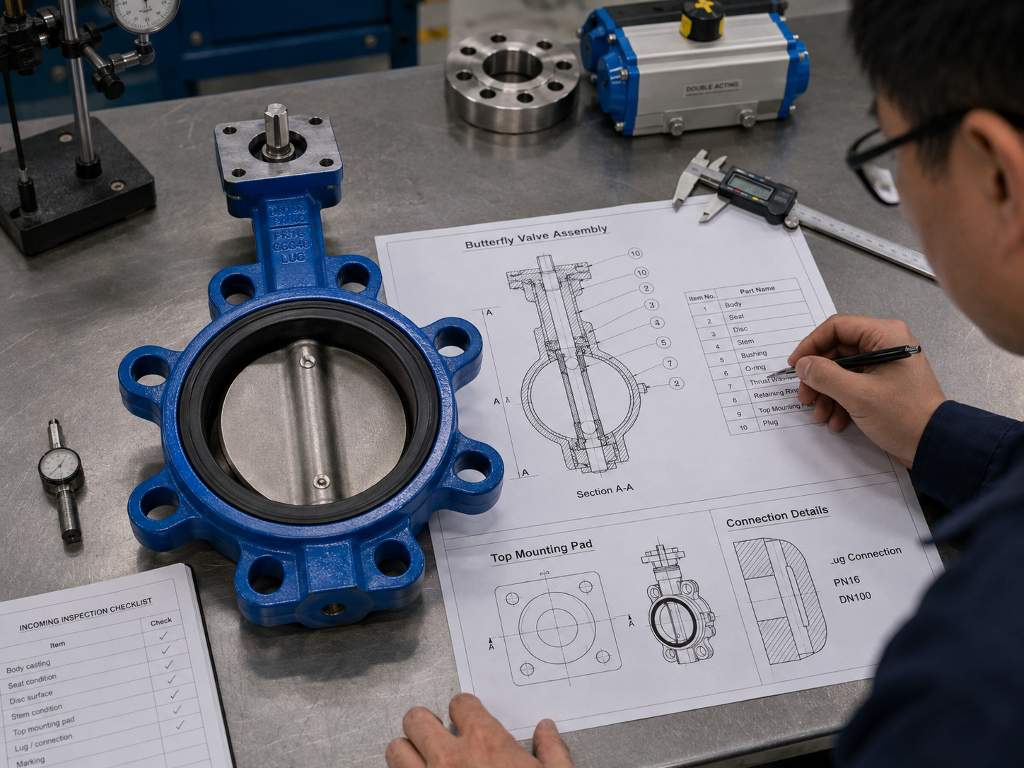
A butterfly valve parts diagram identifies the body, disc, stem, seat, seals, bearings, and operator, while showing how torque reaches the disc and where the valve contains pressure. The labels help you learn the construction, but a generic diagram cannot confirm that a valve or spare part will fit your line.
That distinction matters because similar exteriors can conceal different connections, shafts, seats, and actuator interfaces. RUITO’s industrial butterfly valve range includes wafer, lug, and flanged bodies plus concentric, double-eccentric, and triple-eccentric structures. Identify the diagram type before using its callouts for specification or maintenance.
What a Butterfly Valve Parts Diagram Shows
A butterfly valve parts diagram shows the physical assembly of a quarter-turn valve and the relationship between its pressure-containing, moving, and sealing components.
Do not confuse it with a P&ID symbol. A P&ID shows the valve’s function and control role in a process; a parts diagram shows what is inside the valve. It is also different from a manufacturing drawing, which adds controlled dimensions, tolerances, materials, item numbers, and a revision status.
For basic identification, the diagram should at least show the flow bore, body, disc, stem, seat or liner, shaft seals, supports, and operator. A useful technical drawing also shows the disc-to-seat contact, the stem-to-disc connection, and the actuator mounting interface.
Main Butterfly Valve Parts and Their Functions
The main parts form one mechanical and sealing system: the operator turns the stem, the stem rotates the disc, and the disc closes against the seat. Smaller supporting parts keep that motion aligned and prevent leakage.
The table connects the common callout names with their engineering functions.
| Part | Function | What to confirm on the drawing |
|---|---|---|
| Body | Contains pressure and connects to the pipe | Wafer, lug, or flanged style; material; drilling |
| Disc | Rotates to open, throttle, or stop flow | Profile, material, edge condition, shaft connection |
| Stem or shaft | Transfers torque to the disc | One- or two-piece design; drive shape; wetted area |
| Seat or liner | Creates the primary shutoff interface | Material, retention method, replaceability |
| Shaft seals or packing | Limits external leakage at the stem passage | Seal type, arrangement, gland or cover details |
| Bearings or bushings | Support the shaft and control alignment and friction | Location, material, quantity, thrust support |
| Operator or actuator | Supplies the quarter-turn motion | Lever, gearbox, pneumatic, electric, or hydraulic drive |
| Bracket and coupling | Connect the valve stem to an actuator | Mounting pattern, drive dimensions, orientation |
| Retainer or seat ring | Holds a separate seat or seal in position | Fasteners, pressure side, replaceable items |
| Keys, pins, plugs, and fasteners | Secure or close individual interfaces | Item number, grade, quantity, installation direction |
The term bonnet does not belong on every butterfly valve diagram. Many designs use a top flange, gland, bracket, or cover instead. Follow the controlled parts list rather than assuming two labels are interchangeable.
How the Parts Work Together
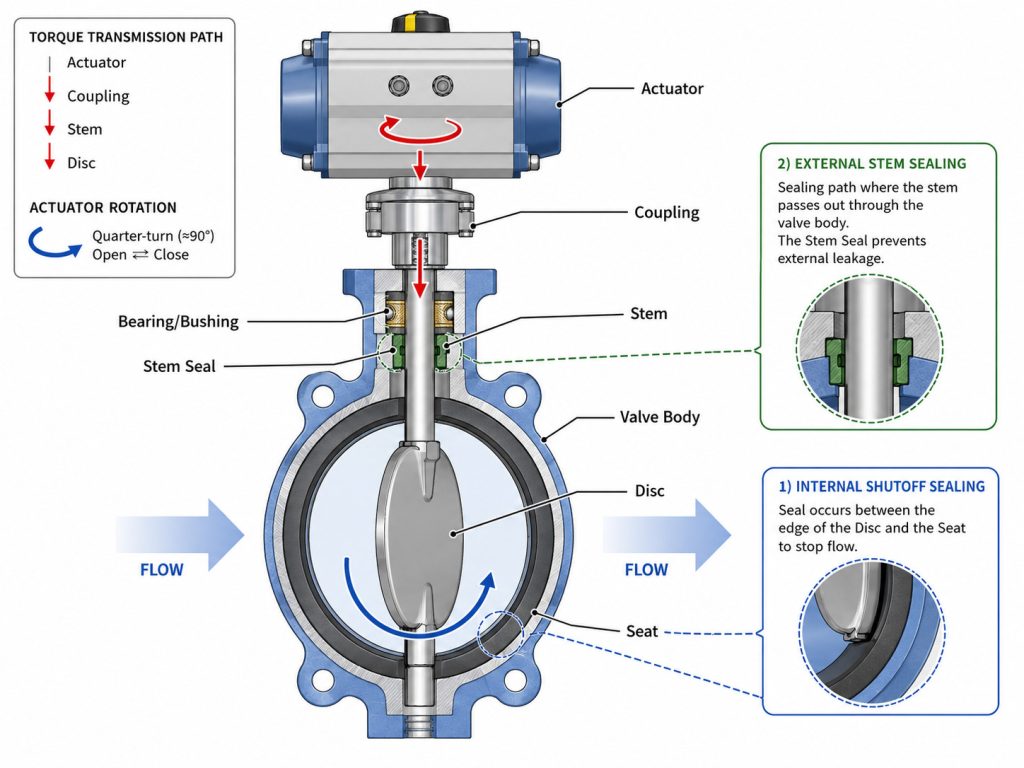
The parts work together through a torque path and two separate sealing paths. Reading those paths is faster than memorizing an isolated list of names.
Trace the Torque Path
Start at the handle, gearbox, or actuator. Torque passes through a coupling or drive socket into the stem, then through a pin, key, spline, or shaped connection to the disc. The bearings and bushings keep the shaft aligned as the disc turns through approximately 90 degrees.
As the disc closes, its edge loads the seat. Do not size an actuator from the drawing; use the manufacturer’s torque data.
Separate Internal and External Sealing
Internal shutoff occurs at the disc-seat interface. External containment occurs at the stem seals, packing, body joints, plugs, and covers. A valve may pass one check and fail the other; acceptable seat shutoff does not prove that the stem seal is sound, and a dry exterior does not prove tight internal isolation.
Why One Diagram Cannot Represent Every Design
One diagram cannot represent every butterfly valve because offset geometry, seat construction, and body connection change both the part list and the way the parts interact. A generic concentric cutaway is a learning tool, not a universal spare-parts reference.
| Design | Distinguishing drawing features | Parts that often change |
|---|---|---|
| Concentric resilient-seated | Stem centered in the disc and bore; elastomer liner around the flow passage | Full liner, split or through shaft, simple shaft seals |
| Double-offset | Stem axis displaced from the seat plane and body centerline; disc cams away from the seat | Separate seat, retainer, packing, thrust components |
| Triple-offset | Additional angular offset creates a conical sealing geometry | Laminated or solid metal seal ring, retainer, pressure-direction details |
Offset designs reduce continuous sliding contact, but their geometry and pressure direction remain manufacturer-specific. Use a high-performance and standard butterfly valve comparison when the section view shows an eccentric shaft or separate seat ring.
Body style changes the outside of the drawing as well. A wafer body sits between flanges and normally uses through-bolting; a lug body has tapped or threaded lugs; a double-flanged body has integral flanges. The current API Standard 609 scope includes double-flanged, lug, wafer, and butt-welding-end butterfly valves, which is a useful reminder to verify the specific construction rather than the valve name alone.
How to Read Section, Exploded, and Outline Views
Each drawing view answers a different question, so use the section, exploded, and outline views together when the decision involves more than basic identification.
- Section view: Follow the pressure boundary, disc-seat contact, shaft path, bearings, and external seals. This is the best view for understanding operation and leakage paths.
- Exploded view: Follow the assembly order and item callouts. This is the best view for finding retainers, washers, pins, O-rings, and other parts hidden in a section.
- Outline or general arrangement view: Check face-to-face length, flange drilling, actuator height, stem orientation, and disc-sweep clearance. This is the best view for installation fit.
No single view proves every condition. A section may omit flange dimensions, an exploded drawing may omit materials, and an outline hides the internal seat arrangement.
For a replacement or installation review, use a documented butterfly valve diagram fit-check workflow rather than comparing only the visible body shape.
Use the Diagram to Verify Four Interfaces
Use the diagram to verify the pipeline, torque, internal-seal, and external-containment interfaces before approving a valve or spare part. This four-interface check turns the picture into an actionable engineering review.
- Pipeline interface: Confirm body style, end connection, nominal size, pressure class, face-to-face length, flange drilling, gasket or liner contact, and disc clearance inside the adjoining pipe. ASME B16.10 supports installation interchangeability only for a defined valve material, type, size, rating class, and end connection; it does not make unlike butterfly valves interchangeable.
- Torque interface: Confirm stem diameter and drive shape, key or coupling, mounting flange, travel stops, required torque, and actuator orientation. ISO 5211:2026 specifies part-turn actuator attachment flange dimensions, driving-component dimensions, and reference interface torques, but the valve’s actual operating torque must still come from its data.
- Internal-seal interface: Confirm the seat material, disc edge, seat retention, preferred pressure direction, and specified leakage test. A drawing shows where sealing occurs; it cannot prove a leakage rating by appearance.
- External-containment interface: Confirm every stem seal, packing set, body seal, plug, cover, and gland that can release process fluid to atmosphere.
For spares, record the manufacturer, model, size, pressure class, serial or batch number, drawing revision, BOM item, material, quantity, and pressure direction. Add clear nameplate and damaged-part photographs. “EPDM seat” is not enough if the profile, hardness, backing, and retention method are unknown.
RUITO’s documented support can include CAD drawings, BOM notes, material certificates, and pressure or seat test reports. These records help connect a callout to the supplied configuration; they do not justify substituting a part from another model without dimensional and material verification. If identification becomes a selection decision, review the relevant butterfly valve characteristics against the actual media, pressure, temperature, and duty.
What Component Clues Point to Common Problems
Component clues narrow a problem to the parts that deserve inspection, but they do not prove the root cause without operating data and a safe physical check. Isolate, depressurize, drain, and lock out the line before disassembling a valve.
| Symptom | Parts to trace on the diagram | Next check |
|---|---|---|
| High or uneven operating torque | Actuator, coupling, stem, bearings, disc, seat | Compare torque history; check alignment, deposits, and seat interference |
| Internal leakage when closed | Disc edge, seat, retainer, stem support | Check debris, damage, wear, alignment, and closure position |
| Leakage around the stem | Shaft seals, packing, gland, stem surface | Locate the leak path and verify seal condition and compression |
| Flange leakage or liner movement | Body, liner, flange face, fasteners | Check centering, flange gap, gasket practice, and bolt loading |
| Wrong position indication | Actuator, coupling, key, stops, indicator | Compare indicator position with actual stem and disc position |
Do not replace the most visible part by default. A damaged seat may be the result of misalignment, a worn bushing, debris, unsuitable material, or incomplete closure. Trace the cause before ordering parts.
Use the Diagram as an Engineering Document
A butterfly valve parts diagram is most useful when it links component names to torque transfer, internal shutoff, external containment, and installation fit. Use generic diagrams to learn the assembly, then move to the controlled drawing, BOM, data sheet, and test requirement for any purchase, repair, or approval decision.
For a project-specific review, send RUITO the valve nameplate, drawing, service media, pressure, temperature, connection, and actuator details through our contact page. We can help match the callouts to a documented valve configuration and identify the information still needed before quotation.
FAQ
Is a Butterfly Valve Parts Diagram the Same as a P&ID Symbol?
No. A parts diagram shows the physical body, disc, stem, seat, seals, supports, and operator, while a P&ID symbol shows the valve’s process function, tag, and control arrangement.
Can I Order a Replacement Seat from a Generic Diagram?
Usually not. Confirm the exact valve model, size, pressure class, drawing revision, seat profile, material, retention method, and item number before ordering.
Does Every Butterfly Valve Have a Bonnet?
No. Many butterfly valves have a top flange, bracket, gland, or cover rather than a conventional bonnet, so the controlled BOM should govern the part name.
Which Butterfly Valve Parts Are Normally Replaceable?
Seats, shaft seals, packing, bushings, bearings, O-rings, fasteners, and operator components are often serviceable, but replaceability depends on the design. Bonded liners, pinned discs, or proprietary cartridges may require factory procedures or larger assemblies.