
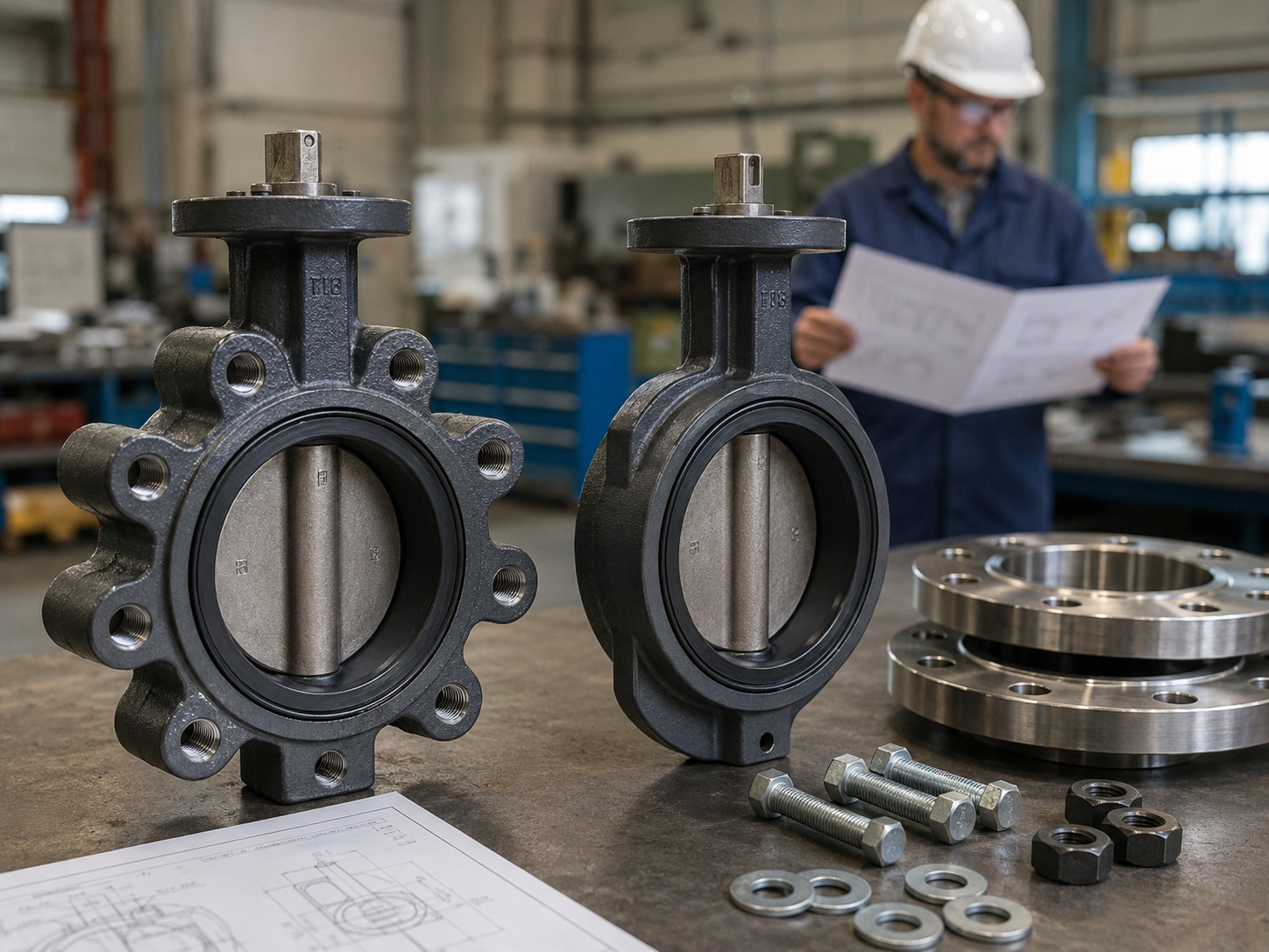
Choose a lugged butterfly valve when each pipe flange must fasten to the valve independently or the design requires rated dead-end service; choose a wafer valve when the valve will remain clamped between two flanges and compact size, low weight, and lower initial cost matter more. That is the practical answer to the lugged vs wafer butterfly valve decision.
The body connection is only the first selection step. It does not, by itself, determine pressure capability, bidirectional sealing, temperature limit, media compatibility, or actuator size. Those limits come from the complete valve design, including the body, disc, shaft, seat, pressure rating, and test basis.
This guide compares the two connections, shows where common shortcuts fail, and gives you a specification path you can use before requesting drawings or quotations for industrial butterfly valve configurations.
The Key Difference Is How the Valve Connects
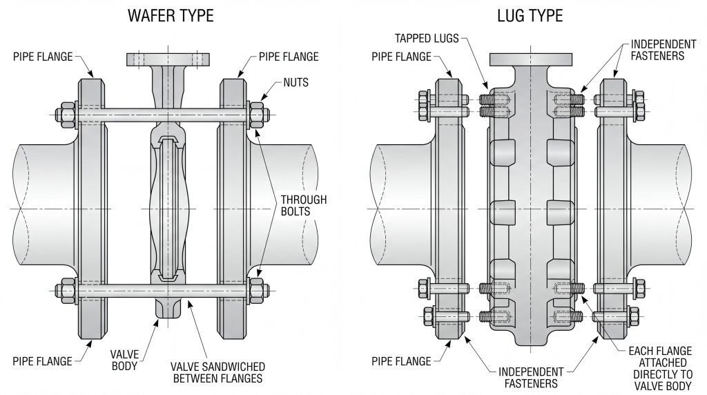
The key difference is that a wafer valve is clamped as part of one flange-to-flange assembly, while a lugged valve is fastened to each flange with a separate set of bolts.
A wafer body sits between the two pipe flanges. Through-bolts or studs connect the flanges and pass around the valve body or through its alignment features. The valve therefore depends on both flanges and the complete bolted joint for retention.
A full-lug body has tapped lugs around its perimeter. Cap screws enter the lugs from each side, so either flange can be secured to the body independently. The word “full” matters: a semi-lug or alignment-lug body may look similar but may not provide a complete set of threaded pressure-retaining connections.
The following table separates the connection facts from assumptions that still require a data sheet or drawing.
| Decision factor | Wafer butterfly valve | Lugged butterfly valve |
|---|---|---|
| Flange fastening | One through-bolted or studded assembly clamps both flanges | Separate cap screws or specified studs fasten each flange to tapped lugs |
| Pipe removal | Normally requires the complete joint to be depressurized and loosened | May permit removal of one piping side when the exact valve is rated for that duty |
| Body size and weight | Usually lighter and more compact | Usually heavier because the lugs add material and machining |
| Initial cost | Usually lower for an otherwise comparable valve | Usually higher for an otherwise comparable valve |
| Alignment | Requires careful centering before final tightening | Full lugs help locate the valve, but bore and disc clearance still need checking |
| Dead-end service | Normally not suitable | Possible only with a documented dead-end rating and correct installation |
| Pressure and temperature | Set by the complete valve rating, not the wafer shape | Set by the complete valve rating, not the lug shape |
| Sealing direction | Set by the seat and valve design | Set by the seat and valve design |
For most projects, the connection choice changes installation and maintenance access. It should not be used as a shortcut for selecting the seat, materials, pressure class, or shutoff direction.
Installation Changes With the Fastener Arrangement
Installation changes mainly in the type, length, and load path of the fasteners. A wafer joint uses fasteners long enough to span the two flanges, valve body allowance, washers, and any specified gaskets. A lug joint uses shorter fasteners from each flange face into the valve body.
Wafer Installation Depends on the Complete Flange Joint
Center the wafer body before fully tightening the flange bolts. Keep the disc slightly open during initial fit-up when the manufacturer’s instructions require it, and verify that the disc can rotate without contacting the pipe bore, liner, or flange inside diameter.
Do not pull badly misaligned flanges into position with the valve bolts. That can distort a resilient seat, create uneven flange loading, and leave the disc off-center even if the joint appears tight.
Lug Installation Is Controlled by the Valve Drawing
For a lugged body, the flange drilling identifies the bolt pattern, but the valve drawing must identify the internal thread and usable lug depth. A generic flange chart cannot tell you the final cap-screw length.
Too-long screws may bottom in blind holes or meet opposing screws in through-tapped lugs before the joint develops the required clamp load. Too-short screws may provide inadequate thread engagement. Use the valve-specific lug butterfly valve bolt chart checks to confirm diameter, thread pitch, installed length, washer allowance, engagement, and bottoming clearance.
Treat Dead-End Service as a Rated Condition
A full-lug body is the normal starting point for dead-end service, but the presence of lugs is not proof that the valve can hold the required differential pressure with one mating flange removed.
Before approving this arrangement, obtain written confirmation of:
- The permitted dead-end differential pressure and temperature
- The pressure direction or whether the rating is bidirectional
- The seat or retainer orientation, if direction affects retention
- The required upstream bolting and flange configuration
- Any reduced rating compared with the normal two-flange installation
- The test basis used to verify the one-flange condition
This distinction matters during pump, strainer, spool, or branch maintenance. A lugged valve can allow one side of the piping to be disconnected without dismantling the other flange connection, but only within the documented limits of that valve.
Dead-end capability is also not permission to expose personnel to stored pressure. Site isolation, depressurization, lockout/tagout, drainage, and verification procedures still govern the work. If the maintenance plan requires positive isolation beyond a butterfly valve’s approved duty, the piping design must provide it separately.
Body Style Does Not Set the Service Rating
Neither wafer nor lug construction alone determines pressure rating, shutoff quality, flow direction, or media suitability. These are properties of the complete valve configuration.
This corrects several common comparison errors. A lugged body does not automatically seal better, and a wafer body is not automatically limited to low pressure. Both connection styles can appear in resilient-seated or offset designs, subject to the manufacturer’s rating and the applicable project specification. The API 609 specification framework is useful because it keeps end connection separate from category, pressure-temperature basis, materials, dimensions, and testing.
Check the following limits independently of body style:
- Pressure and temperature: Use the data sheet rating for the exact body material, seat, size, and design temperature.
- Shutoff direction: Confirm unidirectional or bidirectional closure and the rated differential pressure in each direction.
- Media compatibility: Select body, disc, shaft, and seat materials for corrosion, swelling, erosion, solids, and cleaning chemicals.
- Operating torque: Size the lever, gearbox, or actuator for the worst specified differential pressure and service condition.
- Testing: State the required shell, seat, direction, leakage acceptance, and witness requirements.
RUITO’s current product range includes wafer, lugged, and flanged butterfly valves across DN25–DN3000 and PN10–PN25, with ductile iron, cast iron, carbon steel, stainless steel, and duplex body options plus resilient, PTFE, FKM, and metal seating options. These are portfolio-level ranges; the approved model drawing and data sheet must define the usable combination for your service.
Choose From the Maintenance Plan First
Choose the body connection from how the piping will be installed and maintained, then select the valve design from the actual process duty. This two-stage method prevents a body-style preference from overriding more important service limits.
Use this decision matrix as an initial filter.
| Project condition | Preferred starting point | Why |
|---|---|---|
| Both sides will always be isolated before valve or piping work | Wafer | Independent flange retention offers little added value |
| Skid or plant layout has strict weight and face-to-face constraints | Wafer | The body is generally lighter and more compact |
| Downstream equipment or a spool must be removed while the upstream flange remains secured | Full lug | Each flange has an independent fastener set; rated duty still needs confirmation |
| The valve may serve at the physical end of a pressurized line | Full lug with documented dead-end rating | Body style alone is insufficient; direction and pressure limits must be approved |
| Lowest initial equipment and shipping cost is the main constraint | Wafer | It normally uses less body material and machining |
| Maintenance downtime dominates lifecycle cost | Lugged, if the isolation plan supports it | One-side removal can reduce the scope of piping disassembly |
| Large size, high pipe loads, or a permanently rigid connection governs | Evaluate flanged construction as well | The real decision may extend beyond wafer versus lug |
Wafer valves are common in HVAC, utility water, and compact equipment packages where the line is fully isolated for maintenance. Lugged valves are often preferred around removable equipment, modular process sections, and branch isolation points. In water and wastewater valve applications, either style can be correct; the shutdown plan, coating, seat compatibility, flange standard, and test documentation decide the final configuration.
Prevent Flange and Bolting Mismatches
Prevent fit-up failures by verifying the piping interface and the valve-specific details as two separate layers. Nominal size alone is not enough, and the same nominal size can use different drilling under different standards or pressure ratings.
For ASME projects, ASME B16.5 covers dimensions, tolerances, bolting, gaskets, and flange-joint requirements from NPS 1/2 through NPS 24. That flange information still does not replace the butterfly valve drawing, especially for tapped lug depth or wafer-body allowance.
Before releasing the purchase order, verify:
- Nominal size in DN or NPS
- Exact flange standard, class or PN rating, and facing
- Wafer, full-lug, semi-lug, or flanged body description
- Bolt or cap-screw diameter, quantity, thread series, grade, and coating
- Final installed fastener length, including flange, gasket, washer, and valve-body details
- Face-to-face dimension and available flange separation
- Disc swing clearance against the pipe bore, liner, and adjacent fittings
- External gasket requirement or prohibition for the selected seat design
- Cross-pattern tightening sequence and approved torque or assembly method
- Actuator, gearbox, handle, and maintenance-access envelope
This check prevents a common procurement failure: a valve arrives with the correct nominal size and pressure designation but cannot be installed because the drilling, threads, fastener length, or disc clearance does not match the actual piping.
Write the RFQ Around the Duty
A complete RFQ must define both the process duty and the connection-specific maintenance requirement. “Eight-inch butterfly valve” or even “eight-inch lug valve” leaves too many decisions open.
Include these data groups:
- Process: Media, solids content if relevant, operating and design pressure, maximum differential pressure, operating and design temperature, flow direction, and cycle frequency
- Function: Isolation or control, required shutoff direction, leakage acceptance, fail position, and operating method
- Valve: Size, pressure rating basis, wafer or full-lug body, body/disc/shaft/seat materials, and preferred design standard
- Piping interface: Flange standard and rating, facing, pipe or liner inside diameter, face-to-face requirement, and available installation space
- Maintenance: Whether either pipe side will be removed, whether dead-end duty is required, required differential pressure in that condition, and the site isolation philosophy
- Bolting: Through-bolts or cap screws, diameter, thread, material, coating, washer and gasket assumptions, and drawing-controlled final length
- Quality records: Approved drawing, material certificate, dimensional report, shell and seat test report, dead-end test evidence when required, and inspection or witness points
This specification makes supplier quotations comparable. It also exposes exceptions early: a quoted lug body may fit the flange but lack the required dead-end rating, or a wafer model may meet pressure and material requirements but conflict with the maintenance plan.
Match the Connection to the Real Work
For most projects, wafer is the efficient choice when two-flange clamping is acceptable, while full lug is the stronger maintenance choice when each flange must remain independently attached. The final decision still depends on the exact pressure rating, seat design, flow direction, materials, flange interface, fasteners, and approved maintenance method.
RUITO can review your line data, flange standard, maintenance scenario, and required test documents against available wafer, lugged, and flanged configurations. Send the project specifications for a technical review before the valve and fasteners are released for purchase.
Frequently Asked Questions
Can a Wafer Butterfly Valve Replace a Lugged Valve?
Yes, but only when the piping will not rely on independent flange retention or dead-end service. You must also recheck fastener type and length, valve centering, face-to-face dimension, disc clearance, pressure rating, seat materials, and the maintenance isolation plan.
Do Wafer Butterfly Valves Need Separate Gaskets?
Not always. Many resilient-seated wafer valves use the seat’s molded flange face as the joint seal and may prohibit extra gaskets, while other constructions require specified gaskets. Follow the exact valve drawing and installation instructions rather than applying one rule to every wafer design.
Are Lugged Butterfly Valves Threaded Pipe Connections?
No. The lugs contain tapped holes for flange fasteners, but the process connection remains a flanged pipeline interface. Match the lug thread, bolt circle, and pressure rating to the mating flange and project specification.
Is a Lugged Valve Always More Expensive Than a Wafer Valve?
Its initial price is usually higher for a comparable size, rating, materials, and seat because the body uses more material and requires tapped lugs. Lifecycle cost can favor the lugged option when independent pipe removal materially reduces shutdown time and disassembly work.