
Check triple offset butterfly valve flow direction against the selected model's marking, installation instructions, and directional shutoff ratings. Normal process flow may differ from the pressure direction that governs a closed valve. A documented review of both conditions helps buyers and installers avoid an orientation decision based on valve appearance or a general diagram.
1. What sets triple offset butterfly valve flow direction?
The selected valve's approved documentation and markings set its installation direction. Triple offset butterfly valve flow direction cannot be determined from the number of offsets alone. Identify the exact construction, size, pressure class, and sealing arrangement before applying an instruction, because a rule for another model may describe a different pressure-assisted sealing behaviour.
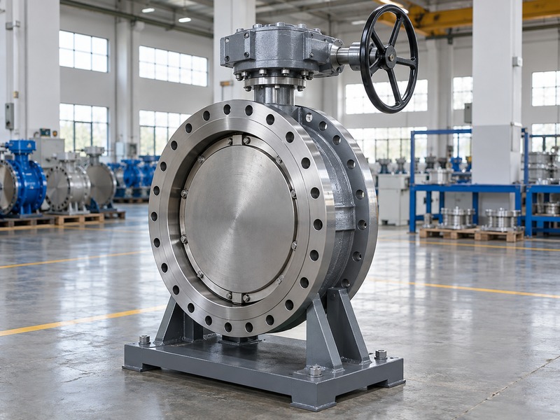
Match the instruction to the valve
Obtain the installation, operation, and maintenance manual together with the approved data sheet and assembly drawing. Check that their model and revision cover the delivered item. Where a project-specific instruction modifies a general manual, have the supplier identify that change and its applicable configuration in writing.
Locate the actual direction marking and confirm what it means. It may identify the manufacturer's preferred installation or pressure direction rather than describe every possible operating case. If the marking and project drawing conflict, resolve the discrepancy before the valve enters the line.
- Identify the delivered valve and document revision.
- Read the marking with the applicable instructions.
- Close conflicting instructions before installation.
| Source | Question it should answer |
|---|---|
| Valve identification | Which construction was supplied? |
| Direction marking | What direction does it designate? |
| Approved instructions | How does that direction apply? |
2. How does fluid flow differ from pressure direction?
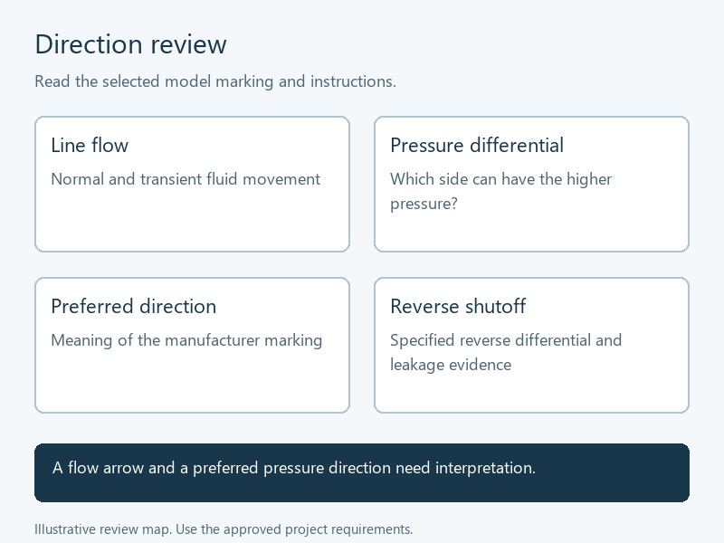
Fluid flow describes movement through an open or partly open valve, while differential pressure describes the pressure difference across it. Triple offset butterfly valve flow direction reviews need both. A closed valve can have no through-flow yet still hold a pressure differential, with either side becoming the higher-pressure side under different system conditions. Include retained pressure after closure when defining the isolation requirement, even if the operating flow has stopped.
Give each side an unambiguous identity
Use pipe or equipment identifiers for the two sides in project documents. Calling one side upstream can become confusing when pressure or flow reverses. Record which side has higher pressure for each isolation case, and state the differential and temperature the selected valve must withstand in that condition.
Separate design pressure from the actual closing differential. A valve's body rating does not establish an equal shutoff rating in every direction. Keep normal operation, closure, and post-closure conditions distinct on the duty schedule so the supplier can evaluate the relevant loads.
- Identify both sides by fixed plant references.
- Record pressure conditions when closed.
- State closing and retained differential separately.
| Term | What it describes |
|---|---|
| Normal flow | Intended movement during operation |
| Differential pressure | Pressure difference across the valve |
| Pressure direction | Which identified side has higher pressure |
3. What does the preferred pressure direction mean?
The preferred direction is the installation or pressure relationship recommended for the selected design. Triple offset butterfly valve flow direction guidance may connect that preference with its sealing and operating characteristics. It does not create a universal rule that every triple-offset valve must place its shaft on the same side of the process.

Avoid a universal shaft-side rule
Read the selected model's statement about shaft side, seat side, and pressure. Different designs and instructions may use different reference points or recommendations. Translate the instruction into the actual assembly drawing and fixed pipe-side identifiers rather than relying on a remembered shaft-upstream or shaft-downstream phrase. Ask the supplier to annotate that drawing if its written terminology leaves more than one possible interpretation.
Ask whether the preferred direction changes required actuator torque, permitted differential, or guaranteed leakage performance. Record the answer for the proposed configuration. If the preferred relationship differs from normal flow, let the supplier and responsible process engineer resolve the installation against all required operating cases.
- Confirm the manufacturer's defined reference points.
- Relate the instruction to the actual drawing.
- Record the consequences of non-preferred pressure.
| Preferred-direction question | Required answer |
|---|---|
| Which side faces pressure? | Selected model instruction |
| Why is it preferred? | Applicable operating or sealing basis |
| What about the other direction? | Written reverse-duty limits |
4. Does reverse flow prove reverse shutoff capability?
No; permitted flow through an open valve does not establish its closed-valve reverse-pressure rating. Triple offset butterfly valve flow direction approval should distinguish passage of fluid from isolation performance. A bidirectional description needs defined differential, temperature, leakage criterion, and operating conditions before it becomes a usable procurement requirement.
Request directional performance explicitly
Ask the supplier to state allowable closing and holding differential in each required direction. Identify any difference in leakage acceptance or operating torque. A broad statement that the valve works in both directions cannot replace a configuration-specific rating, especially when the project requires the same performance in each direction.
Keep end-of-line service separate. Bidirectional sealing does not automatically approve a valve for isolation with downstream pipework removed, because connection, retention, and loading requirements also apply. Request explicit approval of the actual end condition if maintenance planning depends on that use.
- Separate open-flow permission from closed isolation.
- Obtain ratings for both pressure directions.
- Review end-of-line service as a separate requirement.
| Claim | Evidence still needed |
|---|---|
| Reverse flow permitted | Applicable operating conditions |
| Bidirectional shutoff | Rating and leakage criterion each way |
| End-of-line isolation | Approved connection and end condition |
5. Which operating cases can reverse the differential?
Any operating case that changes pressure on either side can change the required pressure direction. Triple offset butterfly valve flow direction should be checked during startup, shutdown, standby, maintenance isolation, and credible system transitions. Use the actual process review rather than assuming the normal running condition governs every closed-valve case.
Build a pressure-case schedule
For example, if a pump stops while a connected header remains pressurised, the pressure relationship across an isolation valve may reverse. Whether that occurs depends on the piping, other valves, control sequence, and equipment. Describe it as a condition to evaluate, not an assumed event in every pumping system.
Include hydrostatic head, trapped sections, parallel equipment, and test arrangements where they affect the valve duty. Have the responsible engineer define credible cases and required acceptance. Keep unresolved pressure assumptions visible instead of silently accepting the valve's normal-flow arrow as the complete design basis.
- List normal and non-running operating states.
- Identify the higher-pressure side in each state.
- Submit the governing cases with the enquiry.
| Operating state | Pressure question |
|---|---|
| Normal running | Which way does fluid move? |
| Pump stopped or standby | Can header pressure dominate? |
| Isolation or testing | Which side remains pressurised? |
6. How do shaft and actuator orientation affect installation?
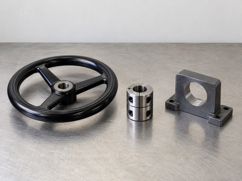
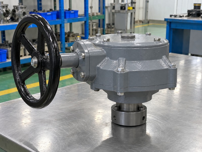
Shaft and actuator orientation describe the installed mechanical arrangement, while pressure direction identifies the applied pressure relationship. Triple offset butterfly valve flow direction needs a separate check from handwheel position, shaft inclination, or actuator access. Rotating an operator for convenient access does not by itself confirm the correct pressure-side installation.
Check direction and access together
Review the manufacturer's allowed shaft orientation, disc-clearance requirements, supports, and maintenance access. An acceptable pressure direction may still produce an assembly that collides with a platform or nearby pipe. Check the complete drawing before making an installation choice that will be difficult to reverse after bolting and wiring.
RUITO's butterfly valve orientation guide provides broader installation context. Apply the selected triple-offset model's instructions to the final arrangement, including any restrictions on changing actuator mounting. Retain the approved relationship among shaft, coupling, operator, and valve position indication.
- Check permitted shaft position independently.
- Confirm open-disc and operator clearance.
- Record the approved assembly orientation.
| Orientation item | Separate check |
|---|---|
| Pressure side | Directional performance requirement |
| Shaft position | Model-specific mounting instruction |
| Actuator position | Access, support, and approved interface |
7. What should you verify during replacement?
Verify the replacement against the actual line duty and its own approved instructions. Triple offset butterfly valve flow direction should be reassessed even when the new valve resembles the removed item. The old installation may use a different sealing design, and matching face-to-face dimensions cannot establish matching directional performance.
Compare the replacement as a complete assembly
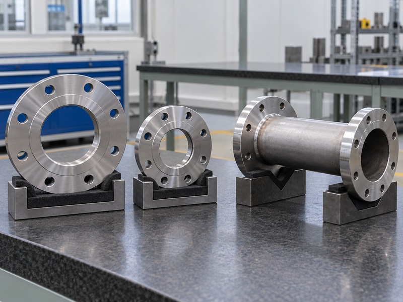
Identify both pipe sides before removing equipment, then compare the proposed marking and drawing with those fixed references. Check flange pattern, bore clearance, face-to-face length, operator envelope, and weight. A replacement that needs revised supports or an altered coupling must have those changes included in its approved scope.
Use RUITO's documented flanged butterfly valve configurations only as a separate connection and construction comparison. That information does not establish a triple-offset range or transfer directional ratings between products. Request confirmation for the exact proposed replacement before ordering it.
- Preserve fixed pipe-side identification.
- Check dimensions and directional duty separately.
- Obtain approval for changed interfaces or supports.
| Replacement detail | What must match the duty |
|---|---|
| Sealing direction | Required pressure cases |
| Installation fit | Actual pipe and assembly dimensions |
| Operator assembly | Torque, coupling, and access |
8. Can torque adjustment correct an unsuitable direction?
Extra closing torque cannot be assumed to correct an unsuitable directional rating. Triple offset butterfly valve flow direction and actuator selection belong to the approved assembly design. Use the manufacturer's setting procedure, required torque, and allowable drive loads; an arbitrary increase may overload the shaft, seal, coupling, or operator.
Investigate the cause before changing settings
If closure performance differs from the requirement, confirm the applied pressure direction, actual differential, seating method, travel stops, and assembly condition. Check that the actuator delivers the required output under its available supply. A closed-position indication alone cannot establish adequate seating load or the specified leakage performance.
Keep the operator installed and maintained as the selected instructions require. Do not remove an actuator from a pressurised valve to inspect direction or reposition the assembly. Plan isolation, depressurisation, stored-energy control, and any adjustment through the applicable site procedure and manufacturer instructions.
- Confirm duty and configuration before adjustment.
- Keep output within approved component limits.
- Reverify function after authorised setting changes.
| Observed issue | Check before adjustment |
|---|---|
| Leakage in one direction | Rating and actual pressure case |
| Incomplete seating | Travel, output, and obstruction |
| Unexpected indication | Sensor setup and mechanical position |
9. What directional test evidence should you request?
Request closure-test evidence for each direction required by the contract. Triple offset butterfly valve flow direction claims need a traceable connection to the selected construction and stated test conditions. A shell-pressure result establishes a different aspect of acceptance from a closure test and cannot prove equal sealing performance in both directions.
Read the test conditions with the result
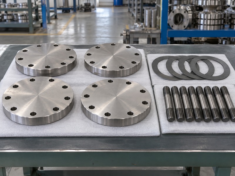
Record the pressurised side, differential, test medium, duration, leakage criterion, and assembly identification. Check which operator and settings were used where relevant. A single result labelled passed leaves too much uncertainty if the purchase requires reverse shutoff under a different condition.
Where specified, ISO 5208 addresses pressure-boundary integrity and closure tightness for metallic valves alongside the applicable product standard. Define the contract's directional test requirements explicitly. The cited scope does not provide a complete site pressure-testing safety procedure or establish the valve's operating rating by itself.
- Link test records to the supplied configuration.
- Identify the pressure side for closure tests.
- Retain the acceptance criterion and conditions.
| Test evidence | What to verify |
|---|---|
| Shell test | Applicable pressure-boundary acceptance |
| Directional closure test | Side, conditions, and leakage criterion |
| Assembly function | Operator configuration and final settings |
10. How should you release the final direction decision?
Release installation only after the actual valve, required pressure cases, and approved orientation agree. Triple offset butterfly valve flow direction should appear in the final drawing and inspection record with fixed pipe-side references. Keep any reverse-duty limitation visible for operations and maintenance personnel after commissioning.

Give installers a traceable instruction
Use a signed review that identifies the valve, applicable instructions, direction marking, pressure-case schedule, and accepted test evidence. Resolve deviations before shipment or installation rather than leaving the installer to choose between conflicting documents. Check that commissioning staff can recognise the approved arrangement without guessing from actuator position. Preserve that decision when replacing an actuator, changing pipework, or revising the operating sequence later.
- Confirm the required shutoff rating in each direction.
- Match the delivered marking with the approved drawing.
- Retain revisions and operating restrictions in the handover pack.
| Release item | Required agreement |
|---|---|
| Process duty | Governing pressure cases accepted |
| Installation | Marking, drawing, and line references aligned |
| Handover | Ratings, tests, and restrictions retained |
RUITO's manufacturing and documentation information provides background for a technical enquiry. Confirm specific triple-offset availability and any special qualification for the proposed order. Contact us with the line references, pressure cases, installation drawing, and directional acceptance requirements for a configuration-specific review.
Questions buyers ask about valve direction
Q1. Should the shaft always face upstream?
No universal shaft-side rule applies to every design. Follow the selected model's marking, instructions, and approved directional ratings.
Q2. Can a closed valve have a reverse-pressure duty?
Yes. Fluid need not pass through the closed valve for the higher-pressure side to change. Review the actual system states.
Q3. Does bidirectional sealing approve end-of-line service?
No. Obtain separate approval for the actual connection, end condition, loading, and operating requirements before relying on that maintenance arrangement.
Q4. Can I turn the actuator to correct pressure direction?
Actuator mounting and valve pressure direction are separate checks. Any permitted remounting must preserve the approved coupling, travel, and indication arrangement.
Q5. What if the valve marking conflicts with the drawing?
Stop the installation decision and obtain the supplier's written resolution for the identified valve. Update the approved records before proceeding.