
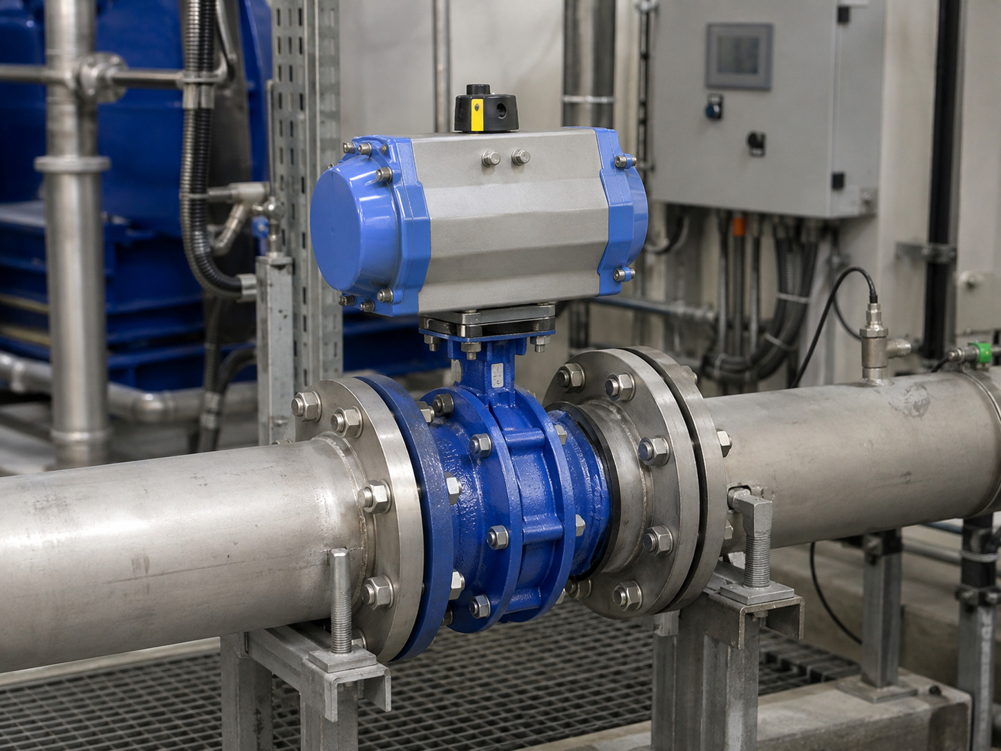
Butterfly valve flow characteristics are nonlinear, design-specific relationships between disc position and flow capacity, and stable control depends on applying the exact valve curve to the pressure drop available in the actual system.
A common failure begins with a line-size butterfly valve selected from its full-open Cv. Once automated, it hunts near one end of travel and barely changes flow near the other. The valve may have enough capacity, yet the system does not give the actuator a usable control range.
The practical solution is to treat the curve as a capacity map, not a promise of installed flow. You must identify what the published curve represents, recalculate each operating case with real pressure conditions, and verify capacity, controllability, and hydraulic integrity separately.
What a Butterfly Valve Flow Curve Actually Represents
A butterfly valve flow curve represents the relationship between disc position and flow capacity under defined test conditions. It does not show the flow your installed system will automatically deliver at each position.
Manufacturers normally express capacity as Cv in U.S. customary units or Kv in metric units. For a water-like liquid under ordinary turbulent, noncavitating conditions, the familiar screening relationship is:
Q = Cv × sqrt(Delta P / SG)
Here, Q is flow in U.S. gallons per minute, Delta P is valve pressure drop in psi, and SG is liquid specific gravity. Rearranging the equation gives the required Cv for a known duty point. A detailed butterfly valve pressure-drop calculation must still use the coefficient at the expected disc angle, not only the full-open value.
The distinction matters because Cv is capacity at a standardized pressure relationship, while actual flow also depends on the rest of the system. A graph labeled “percent of maximum flow” is even less specific: it may be a normalized Cv curve rather than a prediction of installed flow.
Why the Curve Is Nonlinear
The curve is nonlinear because rotating the disc changes the effective opening, separation pattern, pressure recovery, and wake at different rates. Equal increments of shaft rotation therefore do not create equal increments of Cv.
Near the closed position, fluid passes through narrow openings around the disc, so local velocity and pressure gradients can be severe even when total flow is low. Through the middle of travel, changes in disc angle usually produce a more useful capacity response. Near full open, the disc becomes more aligned with the pipe, and further rotation may add little capacity.
This shape is not universal. An open-access numerical study of butterfly valve flow evaluates Cv as a function of opening and shows why size, disc geometry, pressure distribution, and the flow model matter. A generic “equal-percentage” label cannot replace the curve for the exact valve being specified.
Inherent and Installed Characteristics Are Different
The inherent characteristic is measured with pressure drop across the valve held constant, while the installed characteristic includes the changing pump head and piping losses of the real system. Only the installed characteristic tells you how valve movement will change process flow.
In a centrifugal-pump system, pump discharge pressure commonly falls as flow rises while losses through pipe, fittings, strainers, and exchangers increase. The pressure drop left for the valve can therefore shrink at high flow. The same increase in Cv then produces a smaller increase in actual flow than the inherent curve suggests.
The International Society of Automation’s explanation of control-valve characteristics describes this interaction in terms of valve pressure-drop decay. For selection, calculate valve pressure drop at minimum, normal, and maximum flow, then plot or tabulate the resulting valve position. A single design-point calculation cannot reveal a flat high-flow response or an excessively sensitive low-flow region.
How to Read a Manufacturer’s Cv Curve
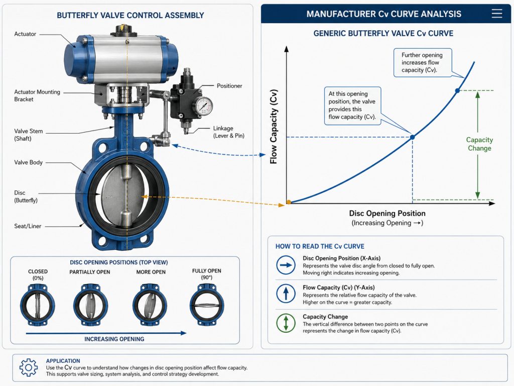
Read a manufacturer’s Cv curve only after confirming the axis convention, units, valve identity, and test basis. Four checks prevent most curve-reading errors:
- Confirm the position reference. Verify whether zero degrees means closed or open, and whether the horizontal axis shows shaft angle, actuator travel, or percent opening.
- Identify the vertical quantity. Determine whether the graph gives actual Cv or Kv, percent of full-open capacity, flow at a stated pressure drop, or a dimensionless loss coefficient.
- Match the exact construction. Size, concentric or offset geometry, disc profile, shaft arrangement, seat, and body pattern can all change the curve. Do not transfer data between nominally similar valves.
- Check the test conditions. Record the fluid, temperature, pressure-tap arrangement, flow regime, applicable method, and whether reducers or adjoining pipe losses are included.
When assessing RUITO butterfly valve configurations, request the performance curve and data sheet for the exact size, disc, seat, body style, and pressure class under review. A full-open Cv alone is sufficient for neither modulating control nor a part-open pressure-drop check.
Define the Usable Control Range from Three Operating Cases
The usable control range is the part of travel that passes minimum through maximum required flow with adequate response, headroom, and hydraulic margin. It should be calculated from the system, not assigned from a universal angle band.
Use this sequence:
- Define fluid composition, temperature, density or specific gravity, viscosity, and vapor pressure.
- Establish minimum, normal, and maximum flow, plus valve inlet and outlet pressure at each case.
- Calculate required Cv or Kv for each operating point using the appropriate sizing method.
- Map each required coefficient to disc position on the exact manufacturer curve.
- Compare the change in installed flow with each small change in position. Look for a reasonably consistent slope through the required range.
- Check cavitation, flashing, noise, velocity, hydrodynamic torque, shutoff torque, actuator resolution, and positioner deadband before approval.
The three acceptance questions below stop “enough Cv” from becoming the only criterion.
| Acceptance question | Evidence to review | Warning sign |
|---|---|---|
| Can the valve pass every required flow? | Cv/Kv at each predicted angle and available pressure drop | Maximum flow uses nearly all available capacity |
| Can the loop regulate across the range? | Installed flow-versus-position slope or installed gain | Operating points bunch together or the curve becomes very steep or flat |
| Can the valve survive the duty? | Cavitation/noise check, velocity, torque, materials, cycle duty | Low-pressure risk, vibration, inadequate torque margin, or seat exposure beyond its limit |
A middle-travel rule can be useful for early screening, but it is not an acceptance standard. The decisive result is whether all three questions pass for the exact valve and system.
What Changes the Curve in Real Service
Valve geometry, size, fluid behavior, piping layout, and actuator performance can all change the relationship between command signal and installed flow. Treat each as a model input rather than a correction after commissioning.
Valve Geometry and Size
A concentric resilient-seated valve, a double-offset high-performance valve, and a triple-offset metal-seated valve should not be assumed to share one characteristic. Disc thickness, edge shape, shaft blockage, seat interference, and diameter alter flow area and pressure recovery. Even when two curves have a similar shape, their actual Cv and usable range may differ.
Fluid and Flow Regime
The simple liquid Cv equation has a defined boundary. IEC 60534-2-1 covers installed-condition sizing for compressible and incompressible control-valve flow, but its standard incompressible equations are not intended for non-Newtonian fluids, slurries, or liquid-solid transport. Those services need validated supplier data or a method suited to the actual rheology and flow regime.
Piping and Actuation
Reducers, elbows, pumps, partially open isolation valves, and nearby equipment change the pressure available at the valve and may introduce asymmetric flow. For offset or directional-sealing designs, also confirm the required butterfly valve flow direction. Finally, include actuator deadband, linkage play, stiction, and positioner resolution: a good hydraulic curve cannot compensate for a valve that cannot repeat its commanded position.
When a Butterfly Valve Is the Wrong Control Element
A butterfly valve is the wrong control element when no available size and construction can meet capacity, installed-gain, and hydraulic-integrity requirements together. Changing the controller tuning does not fix an unsuitable characteristic.
Review another valve type when the duty requires precise control at very low flow, unusually broad turndown, severe pressure reduction, or operation near cavitation or choked-flow limits. The same applies when a slurry or non-Newtonian fluid lacks validated butterfly-valve data, or when the predicted control points occupy only a narrow slice of actuator travel.
A properly selected butterfly valve can provide compact, economical modulation in many large lines. Where the process needs a more deliberately characterized trim and can accept higher pressure loss, a globe valve for critical flow control may provide a more suitable response. Make that choice from the installed calculation, not from a blanket rule about valve types.
What to Put in the RFQ or Control-Valve Review
The RFQ should request an operating-case calculation and configuration-specific curve, not just a nominal size and pressure class. Include the information that changes the hydraulic and mechanical result:
- Fluid composition, solids, density, viscosity, temperature, and vapor pressure
- Minimum, normal, and maximum flow
- Inlet pressure, outlet pressure, and allowable pressure drop at each flow
- Pipe size and schedule, pump curve, static head, reducers, fittings, and nearby equipment
- Isolation or modulation duty, normal position, fail position, shutoff differential pressure, and cycle frequency
- Required body, disc, shaft, seat, connection, pressure class, and design standard
- Requested Cv/Kv-versus-angle curve, full-open coefficient, torque-versus-angle data, cavitation/noise limits, actuator sizing basis, and positioner performance
For a RUITO engineering review, those inputs allow the proposed valve size, operating angle, materials, actuation, pressure-loss result, and documentation package to be checked against the same duty cases. Keep the approved calculation and exact curve with the project data sheet so a later substitute cannot be accepted on nominal size alone.
Put the Curve to Work in Your System
A useful butterfly valve curve does more than show that capacity rises with opening; it connects a specific construction to real pressure conditions and a controllable part of travel. Separate inherent from installed behavior, evaluate three operating cases, and approve the valve only after capacity, response, and integrity all pass.
If you are selecting a modulating butterfly valve, send RUITO the fluid data, three flow cases, inlet and outlet pressures, pipe layout, materials, shutoff duty, and required standards through our project consultation page. We can then review the exact curve, predicted operating positions, pressure drop, torque, and documentation requirements before the specification is released.
Frequently Asked Questions
Does every butterfly valve have an equal-percentage characteristic?
No. Many butterfly-valve curves are described as lying between linear and equal-percentage behavior, but the result depends on construction, size, and the part of travel being examined. Use the exact manufacturer curve rather than assigning a label from valve type alone.
Does 50 percent open mean 50 percent flow?
No. Disc position does not translate directly into either 50 percent Cv or 50 percent installed flow. The curve is nonlinear, and actual flow also changes with the pressure drop available across the valve.
Is a 30-to-70-degree control range always acceptable?
No. A middle-angle range is only a preliminary screen. The acceptable range is where the exact valve passes minimum through maximum flow with suitable installed response, capacity headroom, torque margin, and cavitation or noise performance.
Which flow data should a buyer request?
Request Cv or Kv versus disc angle for the exact valve size and construction, together with test conditions and full-open capacity. For modulating service, also request predicted position, pressure drop, torque, and hydraulic-limit checks at minimum, normal, and maximum flow.