
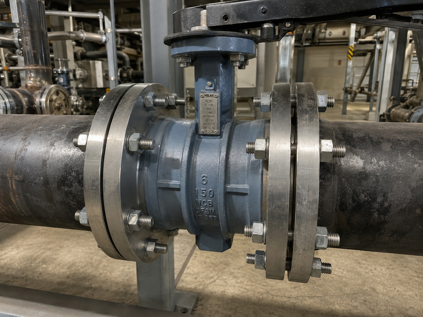
A 150# butterfly valve bolt chart gives the Class 150 flange drilling pattern—bolt count, bolt diameter, hole diameter, and bolt circle—but it cannot give one universal bolt length. Length changes with the valve body style, body width, flange thickness, facing, washers, nuts, gasket practice, and tapped-hole depth.
That distinction matters when you are installing or ordering industrial butterfly valves. A bolt that matches the flange can still be too short to develop adequate engagement, too long for a blind lug, or wrong for a wafer body that sits between two flanges. Use the chart below to confirm the fixed pattern, then complete the length check from the actual valve drawing and installed stack.
What Does 150# Mean on a Butterfly Valve Bolt Chart?
In this context, 150# is common shorthand for ASME Class 150, not a statement that every valve is rated to exactly 150 psi. The actual pressure-temperature capability depends on the valve design, body and bolting materials, seat system, temperature, and applicable valve standard.
ASME B16.5 covers dimensions, tolerances, and pressure-temperature ratings for flanges from NPS 1/2 through NPS 24, including Class 150. It establishes the mating-flange pattern, not the valve body width or universal fastener length.
The clean engineering rule is simple: flange class and NPS determine the drilling pattern; the installed joint determines fastener length.
ASME Class 150 Butterfly Valve Bolt Pattern
The table below gives the fixed Class 150 flange-fit values commonly needed for butterfly valves from NPS 2 through NPS 24. All dimensions are in inches, and “bolts per flange” means the number of holes on one flange face—not necessarily the total number of fasteners required for a complete valve installation.
| NPS | Bolts per flange | Nominal bolt diameter | Bolt-hole diameter | Bolt circle |
|---|---|---|---|---|
| 2 | 4 | 5/8 | 3/4 | 4-3/4 |
| 2-1/2 | 4 | 5/8 | 3/4 | 5-1/2 |
| 3 | 4 | 5/8 | 3/4 | 6 |
| 3-1/2 | 8 | 5/8 | 3/4 | 7 |
| 4 | 8 | 5/8 | 3/4 | 7-1/2 |
| 5 | 8 | 3/4 | 7/8 | 8-1/2 |
| 6 | 8 | 3/4 | 7/8 | 9-1/2 |
| 8 | 8 | 3/4 | 7/8 | 11-3/4 |
| 10 | 12 | 7/8 | 1 | 14-1/4 |
| 12 | 12 | 7/8 | 1 | 17 |
| 14 | 12 | 1 | 1-1/8 | 18-3/4 |
| 16 | 16 | 1 | 1-1/8 | 21-1/4 |
| 18 | 16 | 1-1/8 | 1-1/4 | 22-3/4 |
| 20 | 20 | 1-1/8 | 1-1/4 | 25 |
| 24 | 20 | 1-1/4 | 1-3/8 | 29-1/2 |
For example, NPS 3 uses four 5/8-inch fasteners per flange, while NPS 10 uses twelve 7/8-inch fasteners. Yet “NPS 10, quantity 12” is incomplete until you know whether it describes a wafer fastener set, one flange face, or both sides of a lug valve.
NPS 3-1/2 appears in the flange pattern, but it is not a routine catalog size for every butterfly valve range. Confirm product availability and the dimensional drawing instead of assuming that every listed flange size has a matching standard valve body.
Body Style Changes Bolt Quantity and Length
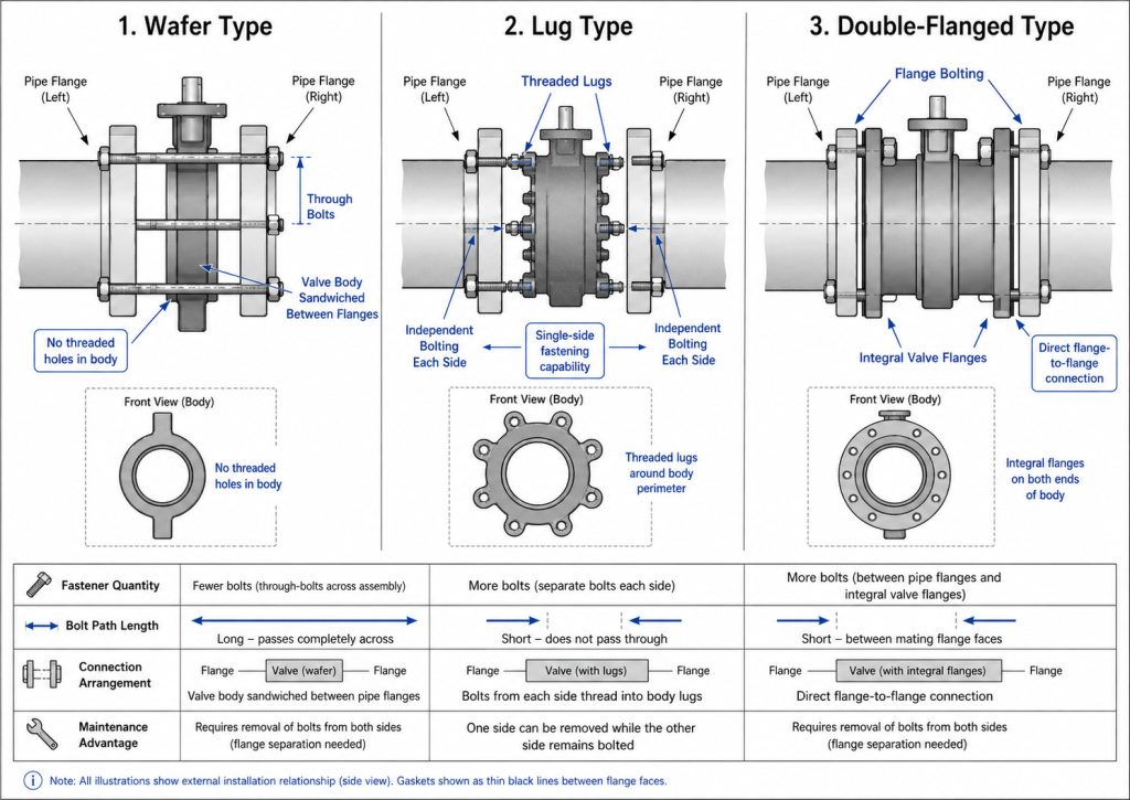
Wafer, lug, and double-flanged bodies can share the same Class 150 drilling pattern while requiring different fastener quantities and lengths. Confirm the wafer or lug body arrangement before converting the flange chart into a purchase order.
Wafer valves use a joint-spanning fastener set
A wafer valve is normally clamped between two pipe flanges by through-bolts or studs. The fastener quantity often equals the number of holes in one flange because each fastener crosses the complete assembly.
The stem neck or body casting can block through-fasteners, particularly on larger valves, so a drawing may require long studs plus short cap screws. Check wafer valve fit and installation risks before releasing the hardware list.
Lug valves use separate fasteners from each side
A lug valve normally has threaded body lugs, so each pipe flange is attached independently. An eight-hole flange pattern commonly needs sixteen cap screws for two sides.
Length must fit the available thread depth. A short screw may lack engagement; a long one may bottom in a blind hole or collide with an opposing screw. Record “quantity per flange” and “total per valve” separately.
Double-flanged valves form two flange joints
A double-flanged valve creates two separate flange joints. Each side uses one flange-face hole count, while length includes the pipe flange, valve flange, permitted gasket, washers, nuts, and thread projection. Valve-flange thickness and facing still come from the drawing.
Determine Bolt Length from the Installed Stack
Final bolt length must be calculated or measured from the actual joint stack, then checked against the manufacturer’s dimensional drawing. A generic length copied from another valve series is only a preliminary estimate.
Wafer through-stud or through-bolt
For a wafer joint, build the length from these components:
valve body width + two pipe-flange thicknesses + permitted gasket allowances + washers + nuts + specified thread projection
A stud normally needs nuts and specified washers at both ends. A machine bolt normally has one nut and is measured from under the head. Use the real stack or controlled drawing dimensions, not nominal pipe size, for body width.
Lug cap screw
For a lug joint, calculate each side independently:
pipe-flange thickness + facing/gasket allowance + washer allowance + required thread engagement
Compare the result with the usable tapped depth. Length must provide the specified engagement without bottoming or colliding. For a lug tapped from both sides, confirm whether threads are continuous and whether opposing screws can share the hole.
Double-flanged stud or bolt
For each joint, include the pipe flange, valve flange, approved gasket, washers, nuts, and thread projection. Add raised faces, special facings, coatings, or insulating hardware only as the approved design requires.
Some resilient seats seal directly against the mating flange, so an extra gasket can change compression and length rather than stop leakage. Verify the valve instructions and butterfly valve gasket requirements before adding gasket thickness.
Know When the General Chart Stops Applying
A general Class 150 chart stops being sufficient whenever the flange standard, size range, valve drilling, or joint hardware differs from its assumptions. Move to the project drawing or approved data sheet when any of these conditions appears:
- The mating flange is EN PN10/PN16, JIS 10K/16K, AWWA, or another non-ASME pattern.
- The flange class is 300 or higher.
- The valve is NPS 26 or larger; ASME B16.47 covers large-diameter steel flanges from NPS 26 through NPS 60.
- The body has blind holes, through-tapped lugs, neck interference, special drilling, or dual-standard drilling.
- Metric fasteners are proposed for inch-series holes or tapped lugs.
- The valve manual prohibits separate flange gaskets or defines a special facing.
- Dead-end service, one-side flange removal, or directional pressure retention is required.
Keep Torque Separate from the Bolt Chart
A bolt chart cannot provide one safe torque value from diameter alone. Required bolt load and installation torque depend on fastener material, coating, lubrication, gasket or seat design, flange condition, tightening method, and the approved joint procedure.
ASME PCC-1 addresses pressure-boundary bolted flange joint assembly procedures and troubleshooting. Use the project procedure, valve installation instructions, and permitted joint standard to define the tightening sequence and target. Do not copy a torque value from a different valve series simply because its NPS and bolt diameter match.
Before tightening, support and align the pipe, center the valve, confirm disc clearance, and load the fasteners progressively in the specified cross-pattern. Bolts should clamp an aligned joint, not pull pipework into position.
Order the Hardware with a Complete Data Set
A complete bolt order identifies the joint, not just the pipe size. Before releasing an RFQ or field kit, record:
- NPS and quantity of valves
- Flange standard, class, facing, and material
- Valve body style, model, and drawing revision
- Hole count per flange and total installed fastener count
- Bolt, stud, or cap-screw type; diameter; thread series; and length
- Tapped-hole type and usable thread depth for lug bodies
- Fastener, nut, and washer material, grade, coating, and lubrication condition
- Gasket or no-gasket requirement
- Required thread projection and approved engagement rule
- Tightening procedure, target load or torque source, and inspection hold points
- Dead-end service or one-side maintenance requirement
This data exposes mismatches before delivery and lets procurement compare hardware quotations on the same joint basis.
Turn the Chart into a Reliable Fit Check
The 150# butterfly valve bolt chart is reliable when you use it to confirm the Class 150 flange pattern, then finish the job with the valve drawing and real joint stack. Bolt count, diameter, hole diameter, and bolt circle are standardized inputs; body style, installed quantity, length, gasket practice, material, and tightening method remain design- or project-controlled.
RUITO supplies wafer, lug, and flanged butterfly valve configurations and can review the mating flange standard, body style, dimensional drawing, and documentation requirements for a project. To check a new or replacement installation, send the valve size and flange details to our engineering team.
FAQ
Can I use this Class 150 chart for a PN16 flange?
No. ASME Class 150 and EN PN16 are different flange systems, even when the nominal pipe sizes look similar. Confirm the specified standard, hole count, bolt circle, hole diameter, and fastener system rather than substituting by DN/NPS alone.
Does a raised-face flange change the bolt diameter?
Not by itself. For the same ASME B16.5 NPS and class, the drilling pattern controls bolt diameter, but the facing and permitted gasket arrangement can change the joint stack and therefore the required length.
Why do two Class 150 butterfly valve charts show different lengths?
They may be based on different valve series, body widths, flange facings, washer assumptions, gasket practices, or fastener types. Compare each chart’s assumptions with the actual drawing; use the shared Class 150 pattern as the fit check, not as proof that the listed lengths are interchangeable.