
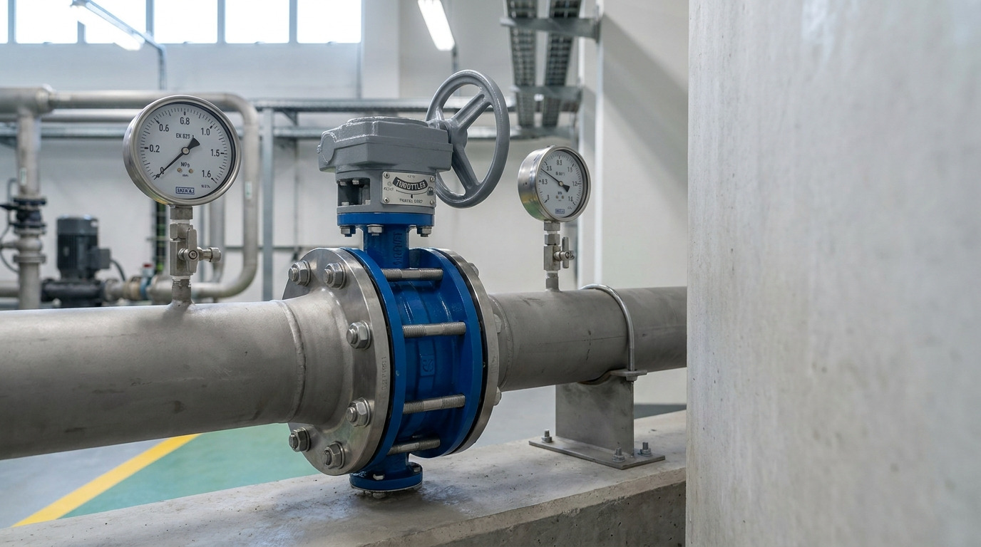
Butterfly valve pressure drop is the pressure lost as fluid passes the disc, shaft, seat, and body, and it matters because that loss changes downstream pressure, pump energy, and control stability. For most liquid services, you should evaluate butterfly valve pressure drop with the manufacturer’s Cv, Kv, or K data at the expected disc opening, not with a generic “butterfly valves are low-loss” assumption.
This topic becomes practical when a pump line meets the required flow on paper, but the actual system loses more pressure than expected after a throttled valve, short reducer, or undersized disc opening is added. The same issue appears when you compare butterfly valves for water, wastewater, HVAC, cooling, marine, chemical, or utility lines where the valve must pass enough flow without becoming an unwanted restriction.
What Causes Butterfly Valve Pressure Drop
The main cause is the disc staying in the flow path, even when the valve is fully open. Unlike a full-bore ball valve or a fully raised gate valve, a butterfly valve still has a rotating disc and stem area inside the bore, so the flow accelerates, separates, and recovers pressure downstream.
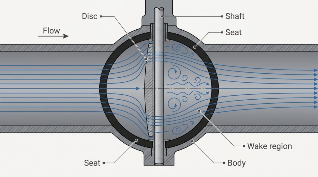
That does not make butterfly valves inefficient by default. It means their pressure drop depends heavily on size, disc profile, opening angle, velocity, and whether the valve is used mainly for isolation or throttling.
Why does a fully open valve still lose pressure?
A fully open butterfly valve normally has moderate pressure loss because the disc edge still creates turbulence and wake behind the shaft. At 90 degrees open, the valve may look clear from the outside, but hydraulically it is not the same as a straight pipe.
For isolation service, that residual loss is usually acceptable when the valve is correctly sized and operating near full open. For high-flow lines, even a small resistance can become important because pressure drop rises roughly with the square of velocity.
Why does throttling change pressure drop so fast?
Throttling changes pressure drop quickly because a small change in disc angle can create a large change in effective flow area. Once the valve is partly closed, fluid velocity through the restricted area rises, turbulence increases, and the recovered downstream pressure drops.
This is why a butterfly valve flow versus percent open check is more useful than assuming 50% open means 50% flow. Butterfly valve flow curves are nonlinear, and the steep part of the curve can create poor control or unexpected energy loss.
How to Calculate Butterfly Valve Pressure Drop
Use Cv or Kv when you have a manufacturer flow coefficient for the valve and disc angle; use K factor when you are modeling pressure loss as part of the piping system. Both methods can be correct, but they answer the problem from different directions.
For liquid service, the basic Cv relationship is commonly written as:
Delta P = SG x (Q / Cv)^2
Here, Delta P is pressure drop in psi, Q is flow in U.S. gpm, and SG is liquid specific gravity relative to water. Cv is defined as U.S. gpm of 60°F water through the valve at 1 psi pressure drop. Kv is the metric equivalent in m3/h of water at 5-30°C with 1 bar pressure drop; a common conversion is Cv = 1.16 Kv and Kv = 0.862 Cv.
When should you use Cv or Kv?
Use Cv or Kv when the supplier provides a flow coefficient curve by valve size and opening angle. This is the normal route for selecting a butterfly valve for a known liquid flow rate and allowable pressure loss.
For example, if water flow is 1,000 gpm and the valve Cv at the selected opening is 2,000, the calculated drop is (1000 / 2000)^2 = 0.25 psi. If the same line uses an opening where Cv is only 500, the drop becomes (1000 / 500)^2 = 4 psi. The flow did not change, but the valve position changed the loss by 16 times.
When a supplier provides a butterfly valve pressure drop chart, check the chart against your actual flow, fluid density, and disc angle. Do not read only the fully open value if the valve will normally throttle.
When should you use the K factor method?
Use the K factor method when the valve is part of a larger hydraulic model and you are calculating losses from velocity head. The common relationship is:
Delta P = K x rho x v^2 / 2
Here, K is the dimensionless loss coefficient, rho is fluid density, and v is average pipe velocity. A butterfly valve K factor is useful when comparing the valve with elbows, reducers, strainers, and other fittings in the same line.
The caution is simple: K changes with disc angle and valve geometry. A fully open K value does not represent a throttled valve.
What Is an Acceptable Pressure Drop
Acceptable pressure drop is the loss your pump, compressor, or process can absorb while still maintaining required downstream pressure and stable valve operation. There is no universal acceptable psi, bar, or percentage for every butterfly valve.
For isolation service, lower pressure drop is usually better because the valve is not meant to consume system energy. For throttling service, some pressure drop may be necessary for control, but too much can create noise, vibration, cavitation, flashing, or wasted pump head.
Can you use a fixed percentage rule?
A fixed percentage rule is usually too rough for real selection. It may help during early screening, but final approval should compare minimum, normal, and maximum flow against the pump curve, downstream pressure requirement, and valve coefficient curve.
A better question is: can the system still deliver the required flow at the worst operating condition? If the answer depends on keeping the valve nearly wide open, the selected size or valve type may need review.
When can too little pressure drop be a problem?
Too little pressure drop can be a problem when the butterfly valve is being used for control rather than isolation. If the valve is oversized, it may sit at a very small opening during normal flow, where small actuator movements create large flow changes.
In hydronic and process control discussions, this is often described as weak valve authority, meaning the valve does not have enough influence over the total circuit pressure loss. The result can be hunting, unstable flow, and poor low-load control.
How Opening Angle Changes Pressure Loss
Opening angle is usually the biggest reason a butterfly valve pressure drop calculation looks wrong. A line-size valve may look large enough, but if normal operation occurs too close to closed, the effective flow path is much smaller than the pipe bore.
Published manufacturer water-service data sheets often recommend avoiding throttling below about 30 degrees open, with better control commonly found around 30 to 70 degrees open for many general butterfly valve designs. Treat that as a practical starting point, not a universal standard, because high-performance, characterized, and resilient-seated valves can behave differently.
Why is 30 to 70 degrees often used for throttling?
The 30 to 70 degree range is often used because the valve has enough opening to avoid severe jetting near the seat, while still retaining enough control movement before it reaches full open. Below about 30 degrees, high local velocity can increase noise, vibration, cavitation risk, and seat erosion in water-like service.
Above about 70 to 80 degrees, pressure drop may become minor for some valves, but control sensitivity can fall because the valve is near its high-capacity end. One open-access experimental study of a 3 in butterfly valve found pressure drop became minor above roughly 70 to 80 degrees under the tested water-flow conditions, but that result should not replace your supplier’s valve data.
How steep is the Cv curve?
The Cv curve is steep enough that opening angle can dominate the calculation. The following example uses a typical published 8 in butterfly valve Cv set for water-like service only to show the curve shape; final values must come from the valve drawing or data sheet.
| Disc opening | Typical Cv for 8 in valve | Calculated drop at 1,000 gpm water | Practical meaning |
|---|---|---|---|
| 30 degrees | 380 | 6.9 psi | High loss and poor place for continuous throttling |
| 50 degrees | 844 | 1.4 psi | More usable control range if noise is acceptable |
| 70 degrees | 1,583 | 0.4 psi | Low loss, but control sensitivity is reducing |
| 90 degrees | 2,110 | 0.22 psi | Best for isolation or near-full-flow operation |
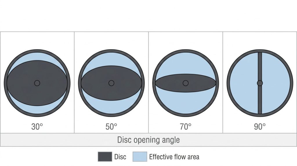
The key point is not the exact Cv number, because that changes by manufacturer and design. The key point is that pressure drop changes with the square of Q / Cv, so a modest-looking change in disc angle can create a major change in pressure loss.
Key Takeaway: A butterfly valve is efficient when it operates in a usable opening range. It becomes expensive when the selection assumes the fully open Cv but the real system runs partly closed.
Liquid, Gas, and Steam Need Different Checks
Liquid pressure drop can often start with Cv or K, but gas and steam require compressible-flow checks before you trust the result. The same butterfly valve can behave very differently when density changes, vapor pressure matters, or the flow approaches choking.
IEC 60534-2-1 provides sizing equations for control valves under installed conditions and distinguishes incompressible and compressible flow. Its incompressible-flow model is for Newtonian fluids and is not intended for non-Newtonian fluids, slurries, or liquid-solid conveying systems without further review.
Can cavitation change the valve decision?
Yes, cavitation can change the decision even when the calculated pressure drop looks acceptable. Cavitation occurs when local pressure falls below the liquid vapor pressure and vapor bubbles collapse downstream, creating noise, vibration, and surface damage.
For water-like liquids, check inlet pressure, outlet pressure, temperature, vapor pressure, and pressure recovery factor if the valve is used for throttling. If cavitation risk is high, a globe control valve, segmented ball valve, different trim, lower velocity, or changed process layout may be safer than forcing a standard butterfly valve into severe service.
Why are gas and steam calculations less forgiving?
Gas and steam calculations are less forgiving because density changes across the valve. In compressible flow, pressure drop cannot be treated as a simple liquid relationship, especially when the ratio of downstream to upstream absolute pressure becomes low.
For steam, air, natural gas, or other compressible media, you need upstream absolute pressure, downstream pressure, temperature, molecular weight or gas properties, and the valve’s compressible-flow data. If those values are missing, any pressure drop number is only a rough estimate.
How Valve Design Changes the Pressure Loss
Butterfly valve design changes pressure loss mainly by changing how the disc sits in the flow and how smoothly pressure recovers downstream. A thin, well-profiled disc usually causes less disturbance than a thick disc, but sealing method, shaft arrangement, seat material, and offset design also matter.
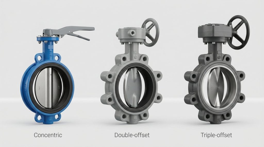
Concentric resilient-seated valves are common in water, HVAC, and general industrial service. Double-offset and triple-offset designs are often selected for higher pressure, higher temperature, tighter shutoff requirements, or more demanding process conditions. The pressure drop difference may be meaningful, but it must be checked against the actual Cv or K curve.
Should you choose a larger valve to lower drop?
A larger valve can lower pressure drop, but it can also make control worse if the valve becomes oversized. If normal flow requires the disc to stay near closed, you may reduce calculated full-open loss while creating unstable throttling.
Good butterfly valve sizing balances pressure drop, disc angle, velocity, shutoff pressure, actuator torque, and seat life. For isolation, line size is often acceptable. For control, a reduced valve size or a different control valve type may give better authority.
Installation Details That Can Distort the Result
A correct Cv number can still produce a poor field result if the valve sees elbows, pump discharge swirl, reducers, or short straight runs. Catalog data is normally developed under controlled test conditions, while field piping may create asymmetric flow into the disc.
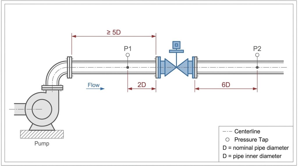
If the valve is installed too close to a pump, elbow, tee, or reducer, dynamic torque may increase and the disc may see uneven loading. That can affect pressure drop, actuator sizing, vibration, and long-term wear.
Where should pressure taps and straight runs be checked?
Pressure taps should be placed consistently when you measure field pressure drop, because readings change depending on whether you measure near the vena contracta, in a disturbed zone, or after pressure recovery. IEC control-valve test arrangements commonly reference pressure taps at 2 pipe diameters upstream and 6 pipe diameters downstream for standardized measurement context.
For installed piping, also review nearby fittings. Some product instructions for butterfly valves use 5 pipe diameters downstream of pumps, elbows, or control valves as a practical layout reference when space allows. If the layout is tighter, include the extra disturbance in your pressure-loss review rather than treating the valve as an isolated component.
This is also where the K method helps. It lets you add the valve, elbows, reducers, strainers, and other minor losses into one system model instead of blaming the valve alone.
What to Confirm Before Final Selection
Before you approve the valve, confirm the pressure drop at minimum, normal, and maximum flow rather than at only one rated flow. A valve that looks acceptable at maximum flow may be unstable at low flow, and a valve that controls well at low flow may consume too much pump head at peak demand.
For a useful manufacturer review, prepare the data that actually changes the calculation:
- Fluid type, density or specific gravity, viscosity, temperature, and vapor pressure
- Minimum, normal, and maximum flow rate
- Inlet pressure, outlet pressure, and allowable pressure drop
- Pipe size, schedule, upstream and downstream layout, and reducer locations
- Valve size, end connection, pressure class, seat material, disc material, and body material
- Required function, such as isolation, manual throttling, modulating control, or emergency shutoff
- Applicable standards such as API 609, MSS SP-67, EN 593, ASME B16.5, ASME B16.34, or project-specific testing requirements
A practical butterfly valve selection review should connect the pressure drop result to actuator torque, seat compatibility, shutoff pressure, and expected operating angle. Pressure drop is not just a hydraulic number; it affects reliability, noise, control behavior, and operating cost.
How do you turn pressure drop into a purchase spec?
Turn pressure drop into a purchase spec by writing the actual operating cases instead of asking only for a nominal valve size. A better request is: “Size this butterfly valve for 1,000 gpm water at 20°C, SG 1.0, normal inlet pressure 6 bar, maximum allowable valve drop 0.5 bar, preferred operation between 40 and 70 degrees open.”
That kind of statement gives the supplier enough context to check Cv, disc angle, velocity, torque, and cavitation risk. Final values should still be confirmed by the valve drawing, certified data sheet, or project-approved calculation.
Conclusion
Butterfly valve pressure drop is controlled by disc obstruction, opening angle, flow rate, fluid properties, and installation conditions. A butterfly valve can be a low-loss, compact, cost-effective choice for many large-diameter and moderate-pressure lines, but the selection must be based on Cv, Kv, or K data at the expected operating position.
If you are comparing sizes, checking a pressure drop chart, or deciding whether a butterfly valve is suitable for throttling, prepare your flow rate, pressure, temperature, fluid data, pipe layout, and preferred standards, then share your service conditions for a more useful sizing discussion.
FAQ
Can I use a butterfly valve for throttling without high pressure drop?
Yes, if the valve is selected to operate in a stable opening range. For many general designs, continuous throttling is more practical around the middle of travel than near closed, but the final decision must come from the valve’s Cv curve, fluid conditions, and cavitation check.
What’s the best way to estimate pressure drop before quotation?
Use the supplier’s Cv or Kv curve at the expected opening. If you do not have that yet, use a preliminary K factor or typical Cv table only for early screening, then replace it with manufacturer data before purchase.
How do I know if my butterfly valve is oversized?
A valve is likely oversized if normal flow requires a very small disc opening, especially below about 30 degrees in water-like throttling service. Other warning signs include unstable flow, noisy operation, frequent actuator movement, or poor control at low demand.
Can I reduce pressure drop by choosing a larger valve?
Sometimes, but it is not always the best answer. A larger valve may reduce full-open pressure loss while making throttling less stable, increasing actuator torque requirements, or moving operation into a poor control range.
What’s the best data to send for a pressure drop check?
Send minimum, normal, and maximum flow, fluid properties, inlet and outlet pressures, temperature, pipe size, layout details, allowable pressure drop, valve function, and required standards. With those details, the valve can be checked against pressure loss, opening angle, torque, and application limits.