
Butterfly valve flow direction depends on valve geometry, sealing design, and which side must hold pressure while closed. A technician may see a body arrow, assume it marks normal flow, and install a valve before checking its data sheet. That shortcut can produce leakage, unstable torque, seat damage, or an actuator that stalls during a process upset. This guide gives you a practical method for reading butterfly valve flow direction, matching orientation with service conditions, and checking each decision before startup.
What Does Butterfly Valve Flow Direction Mean?
The butterfly valve flow direction describes how media approaches a disc and which side applies differential pressure across a closed valve. That relationship affects sealing force, disc loading, torque, and pressure loss. You should assess normal flow, reverse-flow events, and pressure retained after pumps stop.
Why does pressure side matter?
Here is the key: flow can stop while pressure remains trapped on one side. A directional offset valve often seals best when pressure pushes its disc toward its seat.
- Normal operating flow
- Maximum differential pressure
- Static pressure after shutdown
- Possible backflow during a trip
| Condition | Direction check | Main risk |
|---|---|---|
| Pump running | Normal flow path | Dynamic disc load |
| Pump stopped | High-pressure side | Reverse leakage |
| Line isolated | Trapped-pressure side | Seat unloading |
This comparison shows why an arrow alone cannot describe every operating state.
Key Takeaway: Mapping flow and retained pressure helps you choose an orientation that protects shutoff performance.
Do All Butterfly Valves Use One Flow Direction?
No, butterfly valve flow direction may be bidirectional, preferred, or mandatory depending on seat symmetry and disc offset. Concentric resilient-seated valves commonly handle pressure from either side. Double-offset and triple-offset designs often deliver their strongest shutoff in one preferred orientation.
How does valve geometry change directionality?
Centered geometry gives similar disc-to-seat contact from both sides. But there is a catch: an offset disc follows an asymmetric camming path, so reversing pressure can reduce sealing assistance.
- Concentric: usually bidirectional
- Double offset: commonly has a preferred side
- Triple offset: direction depends on tested design
- Custom design: follow certified data
| Valve design | Typical directionality | Selection focus |
|---|---|---|
| Concentric | Bidirectional | Pressure rating both ways |
| Double offset | Preferred direction | Seat-assisted pressure |
| Triple offset | Specified direction | Leakage class and test basis |
Geometry provides a useful screening rule, while supplier ratings settle each application.
Key Takeaway: Never infer bidirectional service from body shape; confirm pressure and leakage ratings in both directions.
What Does the Arrow on a Butterfly Valve Indicate?
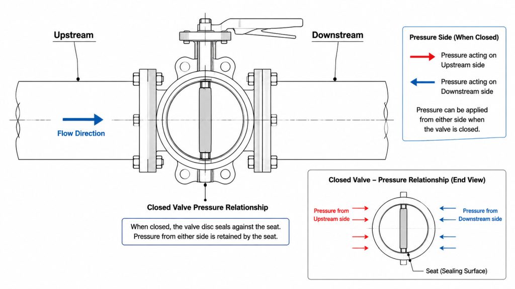
The butterfly valve flow direction arrow may identify normal flow, preferred pressure direction, or the side intended to hold pressure. Its meaning comes from manufacturer drawings and installation instructions. Treating every arrow as a simple fluid-path marker can place a directional seat backward.
How should you decode an arrow?
Check valve documentation against your piping and instrumentation diagram before bolting flanges. Now comes the practical part: ask which side requires rated shutoff after a pump trip or tank isolation.
- Read arrow notes on approved drawings
- Mark upstream and downstream pipe sides
- Identify pressure during closed-valve states
- Record orientation in inspection files
| Arrow meaning | What it identifies | Verification source |
|---|---|---|
| Flow arrow | Normal media travel | Process drawing |
| Pressure arrow | Rated pressure side | Valve data sheet |
| Seat arrow | Preferred sealing side | Installation manual |
A verified document set turns one small mark into a reliable installation instruction.
Key Takeaway: Match arrow meaning with closed-state pressure rather than relying on visual assumptions.
What Happens When a Butterfly Valve Is Installed Backward?
A backward installation can make butterfly valve flow direction work against seat loading and rated shutoff performance. Leakage may start at commissioning or appear after repeated cycles. Higher torque, unstable disc movement, and accelerated wear can follow when hydraulic forces act from an unintended side.
Which failure signs appear early?
Inspect leakage, travel time, actuator current, and closing torque during functional testing. Watch what happens next: a small bypass can cut a narrow path across sealing surfaces and grow under repeated pressure cycles.
- Seat leakage above acceptance limit
- Slow or incomplete travel
- Rising motor current or air demand
- Vibration near intermediate disc angles
| Symptom | Likely mechanism | Immediate check |
|---|---|---|
| Internal leakage | Seat unloading | Pressure side |
| High torque | Unbalanced disc force | Actuator margin |
| Vibration | Disturbed velocity profile | Nearby fittings |
Patterns across several readings usually reveal more than one isolated measurement.
Key Takeaway: Early functional tests let you correct orientation before leakage damages a seat.
How Does Reverse Flow Affect Torque and Actuation?
Reverse butterfly valve flow direction can change hydrodynamic torque across a partly open disc. An actuator sized only for seating torque may lack enough margin during throttling or backflow. Electric motors may overheat while pneumatic units may stall, hunt, or consume excess air.
What should actuator sizing include?
Calculate seating, unseating, bearing, and dynamic torque across expected differential pressure. Here is where it gets useful: a butterfly valve actuator torque calculation should also cover seat aging and abnormal direction events.
- Breakaway torque at closed position
- Running torque through disc travel
- Dynamic torque at peak velocity
- Safety margin based on service duty
| Torque component | Typical source | Design response |
|---|---|---|
| Seating | Seat compression | Verify closing output |
| Bearing | Stem friction | Account for aging |
| Dynamic | Flow across disc | Check both directions |
Dynamic loading often becomes decisive before a valve reaches full opening.
Key Takeaway: Direction-aware sizing protects actuator life and keeps valve travel predictable during process changes.
How Should You Orient a Valve Near Pumps and Elbows?
The butterfly valve flow direction should approach a disc through the straightest practical run near pumps, reducers, tees, or elbows. Disturbed flow creates uneven velocity across disc faces. That imbalance can raise vibration, noise, cavitation exposure, and operating torque.
Which layout checks reduce turbulence?
Use project specifications and supplier guidance for straight-run distances because one universal spacing rule cannot fit every system. Here is the point: stable approach flow matters more than copying a generic diameter count.
- Keep elbows away where space permits
- Avoid placing a disc inside a reducer disturbance
- Review pump discharge velocity
- Give technicians access to actuator and fasteners
| Nearby feature | Flow concern | Layout action |
|---|---|---|
| Pump discharge | Swirl and high velocity | Add straight run |
| Elbow | Asymmetric profile | Increase separation |
| Reducer | Local acceleration | Review disc clearance |
Layout quality can reduce dynamic load without changing valve size.
Key Takeaway: A calm approach profile supports stable torque, lower vibration, and longer seat life.
Which Stem Position Works Best in Slurry and Vertical Lines?
Horizontal stem placement often gives butterfly valve flow direction a cleaner path in slurry service because solids are less likely to collect around the lower stem and seat. Vertical piping requires a separate review of gravity, drainability, entrained air, and potential cavitation. Media behavior should guide orientation rather than installer convenience.
How do media properties change placement?
Review particle size, settling rate, viscosity, and normal pipe velocity. Consider this: a clean-water layout may perform poorly when solids settle during shutdown.
- Horizontal stem for many settling slurries
- Drainable body position for dirty service
- Upward flow where process design permits
- Clearance checks through full disc travel
| Service | Preferred review | Main hazard |
|---|---|---|
| Slurry | Solids settlement | Seat buildup |
| Vertical liquid | Gravity and vapor pockets | Cavitation |
| Gas with condensate | Drain location | Corrosion pocket |
Media behavior can outweigh a generic piping convention.
Key Takeaway: Matching stem position with how your media settles reduces jamming and uneven seal wear.
How Can Smart Actuators Detect Direction Problems?
Smart actuators can reveal butterfly valve flow direction problems through torque, current, position, and travel-time trends. They cannot correct a mechanical installation error by themselves. Yet they can flag a changing load before overheating, seat damage, or loss of travel becomes severe.
Which signals deserve alarms?
Baseline a healthy valve under known pressure and flow conditions, then trend deviations through comparable cycles. The useful clue is this: direction-related trouble often changes several signals at once.
- Peak opening and closing torque
- Motor current or pneumatic pressure
- Travel time and position error
- Cycle count and alarm history
| Signal | Direction-related pattern | Maintenance response |
|---|---|---|
| Torque | Rise after flow reversal | Check pressure side |
| Travel time | Slow stroke | Inspect load and seat |
| Position error | Repeated hunting | Review actuator sizing |
Correlated trends give maintenance teams a stronger diagnosis than a single alarm.
Key Takeaway: A documented baseline turns actuator feedback into early evidence of orientation or sealing trouble.
How Do You Verify Direction Before Commissioning?
The butterfly valve flow direction must be verified against approved drawings, body markings, pressure scenarios, and valve documentation before startup. A field walkdown should also confirm disc clearance and actuator fail position. Record findings so future maintenance crews can reinstall the assembly correctly.
What belongs on a commissioning checklist?
Inspect orientation before final bolt tightening whenever site access allows. This is the checkpoint: a short review now costs far less than draining and reopening a live line later.
- Confirm tag number and service
- Match arrow with documented meaning
- Verify high-pressure side while closed
- Stroke valve under controlled conditions
| Check | Acceptance evidence | Owner |
|---|---|---|
| Orientation | Marked-up drawing | Piping inspector |
| Disc travel | Full stroke record | Commissioning team |
| Shutoff | Leakage test result | Quality team |
Clear ownership prevents a directional check from disappearing between disciplines.
Key Takeaway: A signed orientation record supports safe startup and dependable future reassembly.
How Should You Specify Flow Direction When Buying?
You should define butterfly valve flow direction through operating cases, pressure sides, leakage criteria, and actuator duty in each purchase specification. Avoid vague statements such as “bidirectional” without a pressure rating for both sides. Give suppliers enough process data to select seat geometry and actuator output responsibly.
Which data should an inquiry include?
Provide normal, maximum, and reverse differential pressure plus media temperature and composition. The commercial payoff is clear: precise inputs reduce clarification cycles, substitutions, and site rework.
- Pipe size and flange standard
- Normal and reverse flow cases
- Required shutoff class
- Fail-open, fail-closed, or fail-last action
| Purchase input | Supplier decision | Document requested |
|---|---|---|
| Pressure cases | Seat orientation | Certified data sheet |
| Media and temperature | Wetted materials | Material record |
| Actuation duty | Torque output | Sizing sheet |
Good inquiry data makes technical bids easier to compare.
Key Takeaway: Specify operating scenarios rather than a bare arrow so suppliers can validate valve and actuator performance.
Ready to Put Directional Control Into Practice?
You now have a clear method for interpreting arrows, separating flow from retained pressure, comparing concentric and offset designs, checking torque, and verifying installation before startup. If you need a valve selection reviewed against your media, pressure, piping layout, and actuation duty, contact us today for engineering support and a documented recommendation.
Reliable flow control begins with decisions that field teams can verify. Our position is simple: every valve should arrive with clear technical evidence and perform predictably in its real operating system.
FAQ
Can I install a concentric butterfly valve in either direction?
Usually, yes. Many concentric resilient-seated valves carry bidirectional ratings, though you should confirm allowable differential pressure and leakage performance from product documentation.
What’s the best way to read a valve body arrow?
Use approved documentation. An arrow may mark flow, pressure, or a preferred sealing side, so compare its stated meaning with closed-valve pressure conditions.
How do I know if my butterfly valve is backward?
Check drawings and manufacturer instructions. Unexpected leakage, high torque, slow travel, or vibration can support that diagnosis, though alignment or seat damage may cause similar symptoms.
Can I reverse flow through a double-offset butterfly valve?
Sometimes, within stated limits. Confirm reverse differential-pressure and leakage ratings because performance may differ from the preferred direction.
What’s the best stem position for slurry service?
Horizontal placement often works best. It can limit solids buildup near a lower stem area, though particle behavior, drainability, and supplier guidance should shape your choice.