
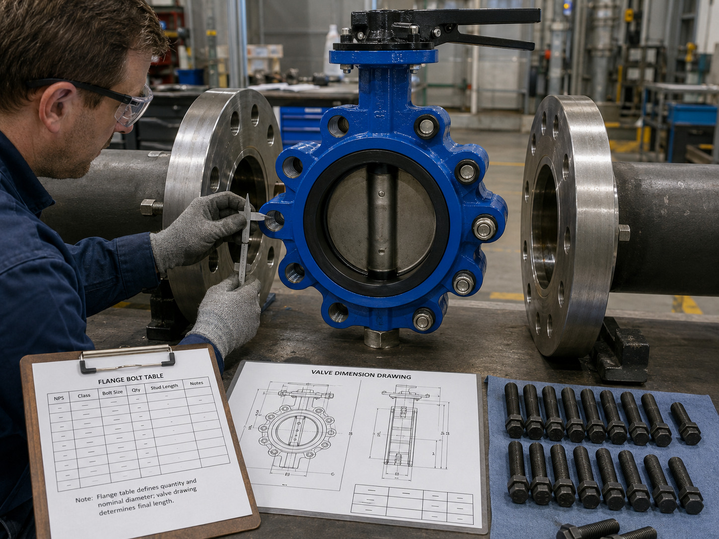
A lug style butterfly valve bolt chart should give the ASME flange bolt quantity and nominal diameter for each NPS, but it cannot give one universally safe cap-screw length. Final length depends on the valve’s tapped-lug geometry and the actual joint stack.
That distinction matters during a replacement or new installation. A screw that is too short may not develop the required thread engagement; one that is too long may bottom in a blind lug or meet the screw entering from the opposite side. If you are matching industrial butterfly valves to ASME flanges, use the chart for drilling geometry, then complete the valve-specific checks below before ordering hardware.
Use the Chart for Flange Data, Not Every Bolt Decision
The chart fixes the mating-flange geometry: NPS, pressure class, bolt quantity, nominal bolt diameter, and bolt-circle diameter. It does not fix the lug thread, usable tapped depth, cap-screw length, fastener grade, coating, washer stack, gasket practice, or target assembly torque.
This separation is important because the same ASME flange can accept different valve body designs. A wafer body normally uses through-bolting, while a lug body normally receives separate cap screws from each flange side. A double-flanged body creates two conventional flange joints. The flange row may be the same, but the length calculation is not.
ASME B16.5-2025 covers dimensions, tolerances, bolting, gaskets, and flange joints from NPS 1/2 through NPS 24. The standard page also confirms that bolt and bolt-hole diameters are expressed in inch units. The table below transcribes the common NPS 2–24 Class 150 and Class 300 drilling entries needed for a preliminary lug-valve match; check the controlled project edition before design approval.
ASME Class 150 and 300 Lug Valve Bolt Chart
This lookup table gives bolt quantity per flange side, nominal fastener diameter, and bolt-circle diameter. It deliberately excludes cap-screw length because that value is valve-specific.
| NPS | Class 150: qty × dia. | Class 150 BCD | Class 300: qty × dia. | Class 300 BCD |
|---|---|---|---|---|
| 2 | 4 × 5/8 in | 4.75 in | 8 × 5/8 in | 5.00 in |
| 2-1/2 | 4 × 5/8 in | 5.50 in | 8 × 3/4 in | 5.88 in |
| 3 | 4 × 5/8 in | 6.00 in | 8 × 3/4 in | 6.62 in |
| 3-1/2 | 8 × 5/8 in | 7.00 in | 8 × 3/4 in | 7.25 in |
| 4 | 8 × 5/8 in | 7.50 in | 8 × 3/4 in | 7.88 in |
| 5 | 8 × 3/4 in | 8.50 in | 8 × 3/4 in | 9.25 in |
| 6 | 8 × 3/4 in | 9.50 in | 12 × 3/4 in | 10.62 in |
| 8 | 8 × 3/4 in | 11.75 in | 12 × 7/8 in | 13.00 in |
| 10 | 12 × 7/8 in | 14.25 in | 16 × 1 in | 15.25 in |
| 12 | 12 × 7/8 in | 17.00 in | 16 × 1-1/8 in | 17.75 in |
| 14 | 12 × 1 in | 18.75 in | 20 × 1-1/8 in | 20.25 in |
| 16 | 16 × 1 in | 21.25 in | 20 × 1-1/4 in | 22.50 in |
| 18 | 16 × 1-1/8 in | 22.75 in | 24 × 1-1/4 in | 24.75 in |
| 20 | 20 × 1-1/8 in | 25.00 in | 24 × 1-1/4 in | 27.00 in |
| 24 | 20 × 1-1/4 in | 29.50 in | 24 × 1-1/2 in | 32.00 in |
BCD means bolt-circle diameter. For a deeper check of hole diameter and Class 150-only entries, use the site’s Class 150 flange drilling reference. Do not convert these inch dimensions into metric and assume an EN, JIS, or PN flange will fit.
Class 300 is not Class 150 with stronger screws. At NPS 6, for example, Class 150 uses eight 3/4-inch fasteners per flange, while Class 300 uses twelve. The pressure class can change the count, diameter, and bolt circle, so use the dedicated Class 300 flange chart when that is the specified interface.
Convert Per-Flange Quantity Into the Installed Total
For a lug body, the chart quantity normally applies to one mating flange, not the complete two-sided valve installation. Calculate the hardware count as:
Total cap screws = chart quantity per flange × connected flange sides
An NPS 4 Class 150 row therefore means eight screws from the upstream side and eight from the downstream side, or 16 screws for a normal two-flange installation. A one-sided dead-end arrangement uses one flange-side quantity only, but only when the valve data sheet identifies the permitted side, direction, and dead-end pressure rating.
Also identify the lug drilling before choosing length. A blind tapped hole has a defined bottom; a through-tapped lug may allow screws to enter from both sides. With through lugs, two individually acceptable screws can still contact each other if their combined penetration exceeds the available path. Treat each side as a separate fit calculation and verify the center clearance on the valve drawing.
Calculate a Safe Cap-Screw Length Window
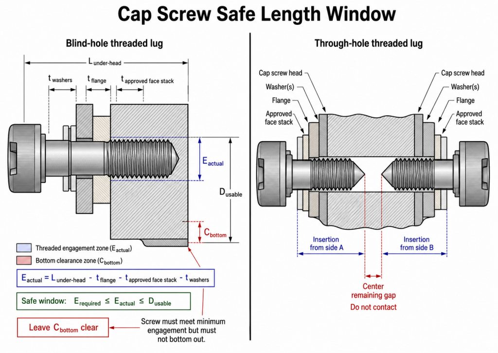
The correct length is the one that provides the drawing-specified engagement without bottoming or contacting an opposing screw. Measure cap-screw length from the bearing surface under the head, then calculate actual engagement:
E_actual = L_under-head − t_flange − t_approved face stack − t_washers
The approved face stack includes only the gasket, spacer, or seat-projection allowance permitted by the valve installation manual. Many resilient-seated designs seal against the flange face without a separate gasket; adding an unapproved gasket changes both length and seat compression.
For a blind tapped lug, accept the selected length only when both conditions are true:
E_actual ≥ E_requiredfrom the approved valve drawing or project calculation.E_actual ≤ D_usable − C_bottom, where usable tapped depth and bottom clearance come from the valve drawing.
If either value is missing, the chart is not sufficient for release. Do not substitute a generic “one diameter of engagement” rule: the required engagement depends on fastener strength, internal-thread material, thread condition, load, and the design basis.
Specify Thread, Material, and Torque Separately
Bolt diameter does not prove thread compatibility. Confirm the thread series and pitch on the valve drawing, gauge the existing thread on replacement work, and state whether the hardware is a cap screw, stud, or machine bolt. Then select grade and coating from the piping material specification, service temperature, corrosion exposure, galvanic compatibility, and site fastener standard.
Torque is also a separate assembly decision because it is only an indirect way to create bolt preload. The same indicated torque can produce a different clamp load when the fastener grade, coating, lubrication, washer surface, or thread condition changes. Never copy a torque number unless its assumptions match the installed joint.
ASME PCC-1-2022 provides guidance for controlled pressure-boundary bolted flange assembly, including procedures and troubleshooting. Its stated scope concerns ring-type gaskets inside the bolt circle, so apply it as project assembly guidance rather than proof that a particular resilient-seated lug valve needs a separate gasket. Use the valve IOM and approved joint procedure for the actual tightening pattern, passes, lubricant condition, and target preload.
Turn the Chart Into an Order and Inspection Record
A release-ready bolting line should contain enough information for purchasing, receiving, and installation teams to reach the same result. Use this structure:
NPS 8 lug butterfly valve; ASME B16.5 Class 150; 8 cap screws per side; 3/4-in nominal diameter; exact thread and length per approved valve drawing; grade/coating per piping specification; washer and gasket rule per IOM; assembly procedure [document number]; dead-end rating [if required].
Before issuing the PO or work pack, require these items:
- Valve general arrangement or dimensional drawing with flange standard, lug thread, usable tapped depth, and body-side clearance.
- Fastener schedule that labels quantity as “per side” or “total per valve.”
- Approved gasket or no-gasket rule, washer stack, coating, and lubrication condition.
- Torque or preload procedure tied to the stated fastener and sealing system.
- Dead-end pressure and direction limits when one pipe side may be removed.
At receiving, compare the nameplate and drawing to the PO, check the bolt circle and hole count without pulling misaligned piping into place, and hand-start the specified screw to confirm thread fit. During installation, stop if the screw seats before the flange is clamped, if the head seats while engagement remains below the drawing requirement, or if the disc binds after the joint is brought up evenly.
Make the Chart a Verified Installation Specification
The chart solves the flange-pattern question; the valve drawing and joint procedure solve length, engagement, and preload. Keeping those decisions separate prevents the most common lug-bolting errors: wrong class, wrong total quantity, mixed thread, insufficient engagement, and bottomed screws.
RUITO’s published butterfly valve range includes lug configurations and ASME B16.5 connection options within the applicable product envelope, with dimensional drawings and project documentation available for technical review. For a project-specific check, send your valve size, flange class, gasket rule, and available drawings to RUITO.
FAQ
Can I use a wafer butterfly valve bolt chart for a lug valve?
Only for shared flange geometry, not for final hardware length. A wafer chart may confirm bolt count and diameter, but its through-bolt or stud length does not represent a cap screw entering a tapped lug.
Why is cap-screw length missing from the ASME chart?
Because ASME flange drilling does not define the valve body’s usable lug depth or the installed face stack. Final length must satisfy the valve-specific engagement and clearance window.
Does Class 150 mean a maximum pressure of 150 psi?
No. Class 150 is a dimensional and pressure-temperature class designation, not a universal 150 psi valve limit. The allowable pressure depends on the valve design, material, temperature, seat, and governing standard.
Can every lug butterfly valve be used for dead-end service?
No. A lug-shaped body does not by itself establish dead-end capability. Confirm the rated pressure, permitted flow direction, seat design, connected side, and required bolting in the valve manufacturer’s documentation.