
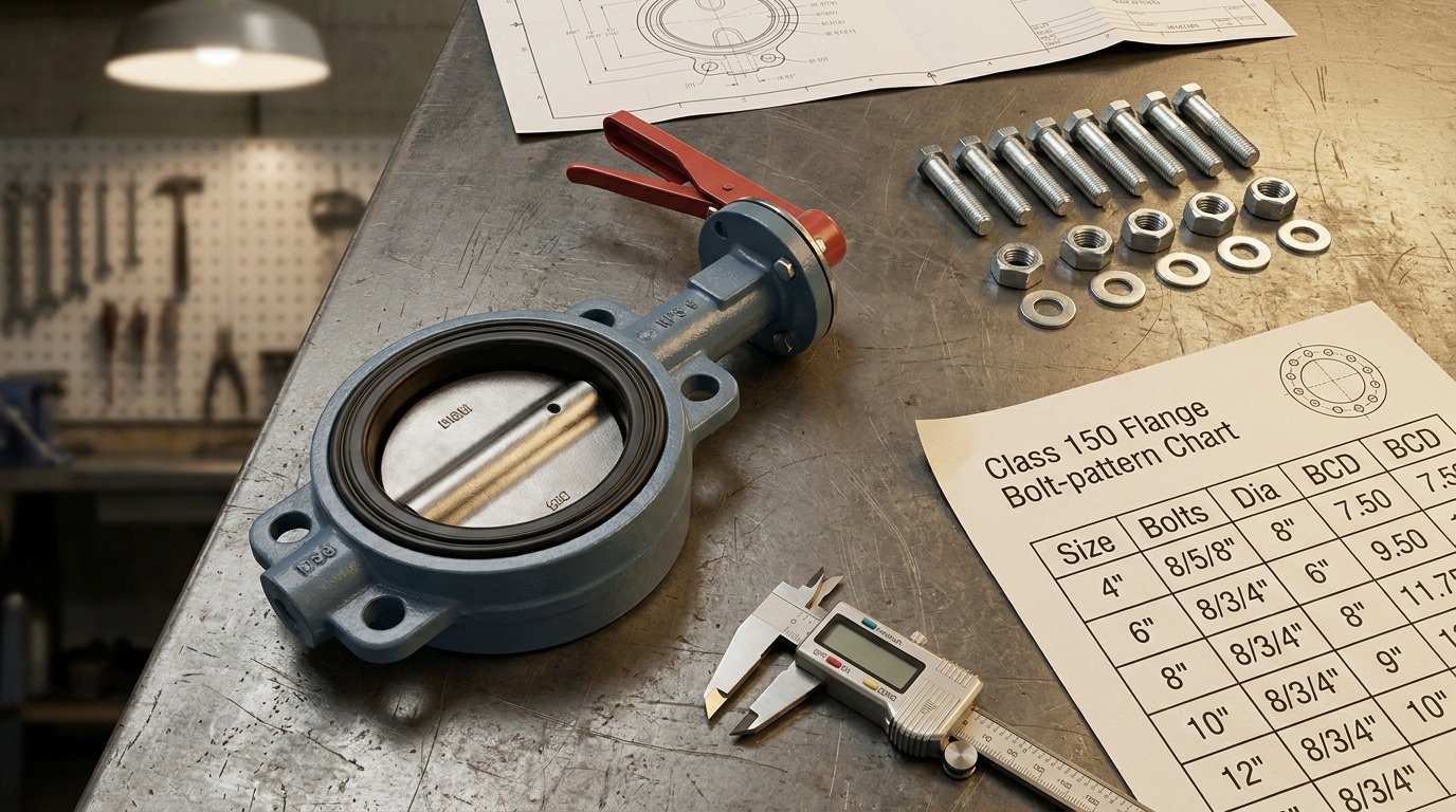
A 150 butterfly valve bolt chart should be read as a Class 150 flange bolt-pattern chart first, then adjusted for the valve body style, gasket condition, and manufacturer drawing before you order fasteners. For a Class 150 butterfly valve, the chart confirms the flange drilling pattern, while the final fastener length depends on whether you are installing a wafer, lug, or flanged body.
A common problem happens when a team sees “150” and orders bolts from a generic flange chart, only to find that the bolts bottom out in lug holes, miss full nut engagement, or over-compress a resilient seat. This guide helps you use the chart correctly, avoid weak assumptions, and prepare clearer specifications for a butterfly valve installation.
How to Read a 150 Butterfly Valve Bolt Chart
A 150 butterfly valve bolt chart tells you the flange drilling pattern, not the complete installation answer. In ASME usage, “Class 150” defines a pressure class and flange dimensional system; it does not mean every valve uses the same bolt length or that the working pressure is automatically 150 psi.
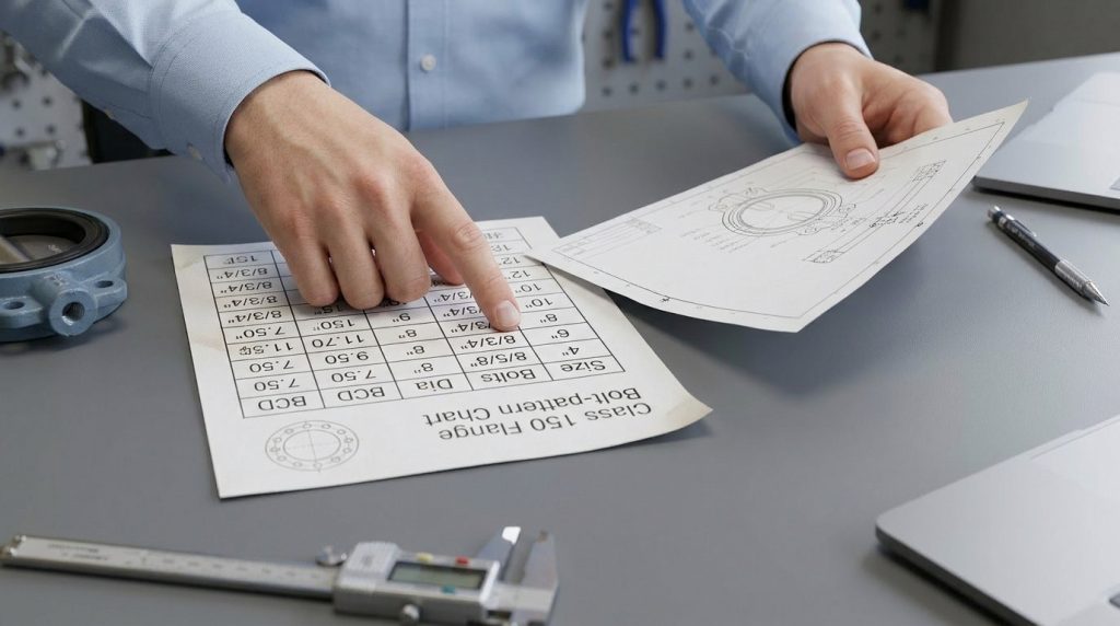
The safest way to read the chart is to separate fixed flange data from valve-specific data. Fixed data usually comes from ASME B16.5 for NPS 24 and below, while valve-specific data comes from the butterfly valve drawing, body style, seat design, and project bolting specification.
Why Class 150 Does Not Mean One Bolt Length
Class 150 controls the matching flange pattern, including bolt circle, bolt quantity, bolt diameter, and bolt-hole diameter. It does not control the thickness of the butterfly valve body between the flanges.
That difference matters because a wafer valve may use through-bolts across the valve body, while a lug valve may use shorter cap screws or studs threaded into tapped lugs. A double-flanged butterfly valve creates two separate flange joints, so its bolting length logic is different again.
Which Values Are Fixed or Project Specific
The fixed values are the ones that must match the mating flange standard. For ASME B16.5 Class 150 flanges, bolt circle and bolt-hole layout are standard dimensions for each NPS size.
The project-specific values include bolt length, fastener material, nut style, washer use, lubricant condition, tightening method, gasket allowance, and thread engagement. These must be checked against the valve drawing and bolting specification, especially when you are comparing butterfly valve sizes across different body patterns.
Class 150 Bolt Pattern Chart for Common Sizes
For ASME Class 150 flanges, the fixed chart values you can use are bolt quantity, bolt diameter, bolt-hole diameter, and bolt circle, not the finished bolt length. The table below summarizes common NPS 2 through NPS 24 Class 150 flange drilling values per ASME B16.5; dimensions are in inches.
| NPS Size | Number of Bolts | Bolt Diameter | Bolt Hole Diameter | Bolt Circle |
|---|---|---|---|---|
| 2 | 4 | 5/8 | 3/4 | 4.75 |
| 2-1/2 | 4 | 5/8 | 3/4 | 5.50 |
| 3 | 4 | 5/8 | 3/4 | 6.00 |
| 3-1/2 | 8 | 5/8 | 3/4 | 7.00 |
| 4 | 8 | 5/8 | 3/4 | 7.50 |
| 5 | 8 | 3/4 | 7/8 | 8.50 |
| 6 | 8 | 3/4 | 7/8 | 9.50 |
| 8 | 8 | 3/4 | 7/8 | 11.75 |
| 10 | 12 | 7/8 | 1 | 14.25 |
| 12 | 12 | 7/8 | 1 | 17.00 |
| 14 | 12 | 1 | 1-1/8 | 18.75 |
| 16 | 16 | 1 | 1-1/8 | 21.25 |
| 18 | 16 | 1-1/8 | 1-1/4 | 22.75 |
| 20 | 20 | 1-1/8 | 1-1/4 | 25.00 |
| 24 | 20 | 1-1/4 | 1-3/8 | 29.50 |
This chart is a strong starting point because it answers the first fit-up question: will the valve drilling match the mating Class 150 flanges? For butterfly valves above NPS 24, do not extend this chart by assumption; larger steel flanges are commonly handled under ASME B16.47 or project-specific standards.
What Sizes Use 4, 8, 12, 16, or 20 Bolts?
Smaller Class 150 flanges in this range use 4 bolts, common mid-size flanges use 8 bolts, and larger sizes step up to 12, 16, or 20 bolts. That step change affects installation time, tightening sequence, and how evenly the seat or gasket is compressed.
For example, NPS 3 Class 150 uses 4 bolts at 5/8 inch diameter, while NPS 10 uses 12 bolts at 7/8 inch diameter. If a purchase request says only “150 butterfly valve bolts,” you still need the NPS size before you can select the correct pattern.
Why Bolt Holes Are Larger Than Bolts
Bolt holes are larger than the bolt diameter to allow assembly clearance and normal flange alignment tolerance. That clearance is useful, but it does not excuse poor centering.
If the valve is forced into position by the bolts, the disc may rub the pipe ID, the liner may deform, or the flange face may load unevenly. The goal is to align the pipe and valve first, then use the bolts to clamp the joint.
Key Takeaway: The chart gives the flange pattern. It does not replace the valve drawing for bolt length, thread engagement, seat compression, or tightening limits.
Wafer, Lug, and Flanged Bodies Change Bolt Length
The valve body style is the main reason one Class 150 bolt chart cannot give a universal bolt length. Two valves with the same NPS and pressure class can need different fasteners if one is wafer style and the other is lug style.
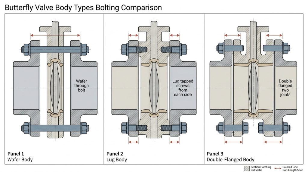
This is where many ordering mistakes begin. The flange chart confirms where the bolts go; the valve construction determines how long the bolts must be and whether they pass through the full assembly or stop inside tapped body lugs.
Can You Use One Generic Length Chart?
You can use a generic length chart only as a rough starting point, not as the final order basis. Standard flange bolting charts often assume flange-to-flange assembly conditions, while a butterfly valve adds body thickness, seat projection, or tapped lug depth.
A practical bolt-length check should account for pipe flange thickness, valve body thickness at the bolt line, gasket or seat condition, washer thickness, nut height, and required thread projection. Final length should always be confirmed against the valve drawing because casting shape and liner design vary by manufacturer.
What to Confirm on Wafer Valves
For wafer-style butterfly valves, many bolts pass through the mating flanges and around or through alignment areas of the valve body. You need enough length for both flanges, the valve body width at the bolt path, any specified gaskets, washers, nuts, and thread projection.
Also check whether the resilient seat acts as the flange seal. Many resilient-seated wafer valves are designed to seal directly against clean flange faces without separate flange gaskets, while some high-performance or special-service valves may require gaskets. Adding gaskets where they are not specified can change compression and increase operating torque.
What to Confirm on Lug Valves
For lug valves, confirm whether the lugs are tapped, whether the tapped holes are blind or through, and how much thread engagement is required. A lug-style butterfly valve often uses separate fasteners from each side rather than one through-bolt across the full joint.
This detail matters in dead-end service, where the valve may be installed with one downstream flange removed under specific pressure limits. Never assume dead-end capability from the lug body shape alone; confirm the pressure limit, seat design, and bolt engagement in the product data sheet.
How to Calculate a Practical Bolt Length
A practical bolt length starts with the flange chart, then adds the physical stack-up of the joint. The correct question is not “What bolt fits a Class 150 butterfly valve?” but “What fastener gives full engagement and correct compression for this valve body between these flanges?”
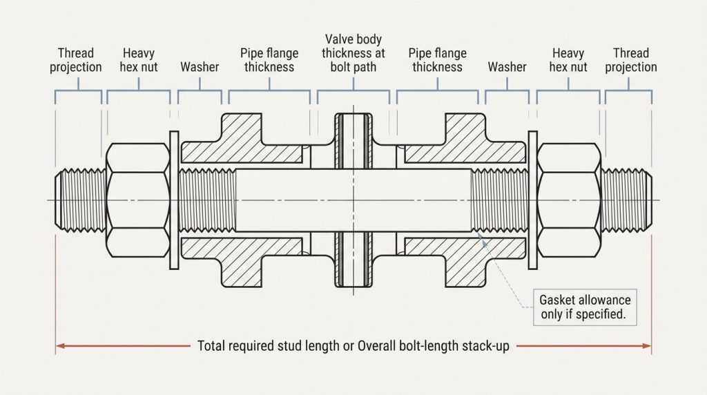
For wafer valves, the stack-up is usually longer because the bolt must span both flanges and the valve body area. For lug valves, the stack-up is usually shorter on each side, but thread depth and bottoming risk become more important.
What Dimensions Should You Add?
For a through-bolted wafer assembly, add the two pipe flange thicknesses, the valve body thickness at the bolt path, any specified gasket thickness, washer allowance, nut height, and required thread projection. If a resilient seat replaces separate gaskets, do not add gasket thickness unless the valve manual allows it.
For a lug assembly, add one pipe flange thickness, specified gasket or seat allowance, washer allowance, and required thread engagement into the tapped lug. Then check that the screw does not bottom out before clamping the flange.
How Much Thread Engagement Is Enough?
The fastener should develop full, usable thread engagement without bottoming, stripping, or leaving the nut only partially engaged. In many industrial flange specifications, ASTM A193 B7 studs with ASTM A194 2H nuts are common for carbon steel bolting, while stainless services may use ASTM A193 B8 or B8M with compatible nuts.
Do not treat material selection as an afterthought. Corrosive media, outdoor exposure, high temperature, galvanic concerns, and plant standards can all change the bolting material and coating requirement.
When Should Studs Replace Cap Screws?
Studs are often preferred when repeated assembly, heavy flanges, larger diameters, or more controlled nut engagement is important. Cap screws are common on tapped lug valves, but they must match thread depth and must not bottom out in blind tapped holes.
If the valve has a gear operator, actuator bracket, or body boss near the flange, check wrench clearance before choosing fastener type. A bolt that is theoretically correct but impossible to tighten evenly can still create a leaking joint.
Installation Checks Before Tightening
Correct installation protects the seat, disc, and flange joint before final torque is applied. A good bolt chart prevents size errors, but careful fit-up prevents leaks and early valve damage.
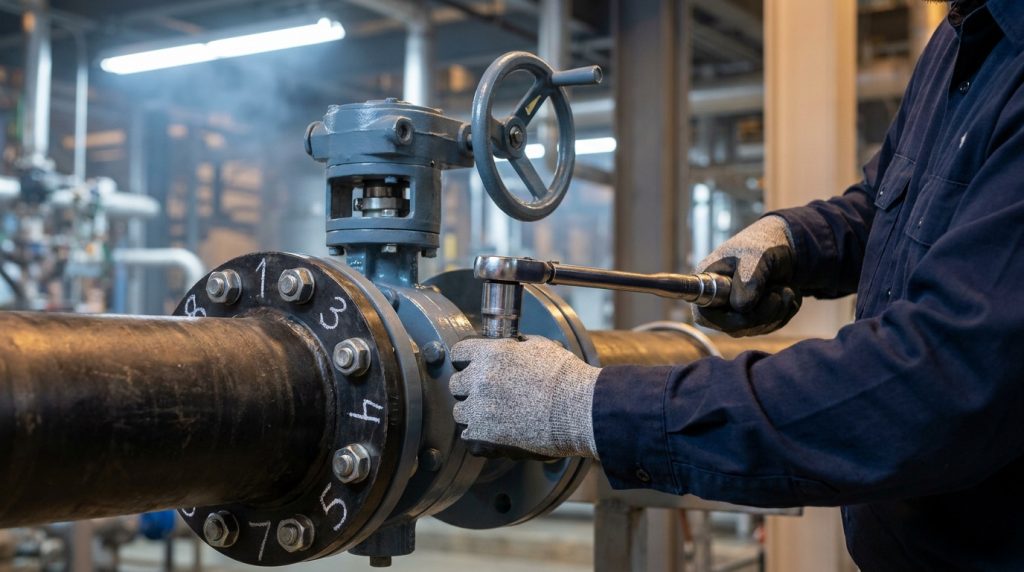
Before tightening, confirm that the flange faces are clean, the pipe is supported, the valve is centered, and the disc can rotate without hitting the pipe ID. This is especially important for resilient-seated butterfly valves because the disc can extend beyond the body face at some opening angles.
Should the Disc Be Open or Closed?
For many resilient-seated wafer and lug valves, the disc is installed nearly closed or slightly open so the disc edge stays inside the body while the seat is not distorted. Some manuals describe this as “almost closed,” and some specify a small opening angle such as about 10 degrees.
Do not install the valve with the disc projecting into the flange gap. Also do not fully clamp a resilient seat while the disc position creates uneven pressure on the liner.
What Is the Right Tightening Sequence?
Use a cross-pattern or star-pattern sequence, then make progressive passes until the joint is evenly seated. ASME PCC-1 is commonly used as a bolted flange assembly guideline, but the target torque must come from the gasket, valve, flange, fastener, and lubricant condition.
For butterfly valves, even compression matters as much as final torque. A valve installed with proper alignment should not rely on bolt force to pull misaligned piping into place.
How Do You Avoid Seat and Liner Damage?
Avoid over-tightening, uneven tightening, and extra gaskets that the valve design does not allow. Resilient seats are designed to compress in a controlled way; too much compression can increase operating torque or damage the liner.
After the bolts are snug but before final tightening, cycle the disc carefully if the installation procedure allows it. If the disc rubs, binds, or feels uneven, stop and correct alignment before applying final torque.
Common Bolt Chart Mistakes That Cause Leaks
Most bolt-related butterfly valve leaks come from using the right chart in the wrong way. The numbers may be correct for the flange, but the installation can still fail if the user ignores body style, flange standard, seat design, or bolt length.
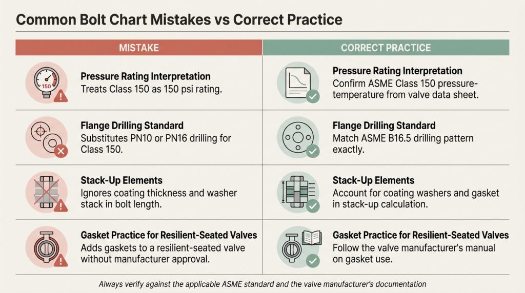
The best prevention is to treat the chart as one part of a specification package. The package should include valve size, pressure class, body style, flange standard, face-to-face standard, fastener material, gasket rule, and tightening method.
Mistaking Class 150 for ANSI 150 psi
“ANSI 150” is often used casually in industry, but the more accurate term is ASME Class 150 when discussing ASME flange dimensions. It is a flange class, not a simple 150 psi pressure rating.
The actual pressure-temperature capability depends on the valve design, body material, seat material, standard, and manufacturer data sheet. A resilient-seated valve may also have a cold working pressure rating that differs from the flange class wording.
Mixing ASME and EN Flange Patterns
ASME Class 150 and EN 1092-1 PN patterns are not automatically interchangeable. Even when the nominal size looks close, the bolt circle, number of holes, bolt size, or pressure designation may differ.
This is a common issue in international projects where pipe spools, valves, and flanges come from different supply chains. If your specification says Class 150, do not substitute PN10 or PN16 drilling unless the drawings explicitly approve it.
Ignoring Coating, Washers, and Gasket Compression
Paint, epoxy coating, thick galvanizing, washers, and gasket thickness can all affect practical bolt length. The effect may look small on paper, but it can decide whether a cap screw bottoms out or a stud has enough nut engagement.
For coated valves and flanges, also confirm that bolt holes are clean after coating. Tight clearances filled with paint can make installers force bolts through the holes, which can shift the valve off-center.
What to Confirm Before Ordering Bolts
Before ordering bolts, confirm the information that affects fit, strength, and assembly, not just the nominal size. A complete inquiry reduces back-and-forth and helps prevent the wrong fasteners from reaching the jobsite.
Use this checklist when preparing a purchase request or checking a supplier quotation:
- Valve size in NPS or DN, and the exact flange class or PN rating
- Body style: wafer, lug, double flanged, grooved, or special design
- Flange standard, such as ASME B16.5 Class 150 for NPS 24 and below
- Valve drawing or data sheet showing body thickness and lug details
- Fastener type: stud, machine bolt, or cap screw
- Fastener material and nut grade, such as ASTM A193 B7 / ASTM A194 2H
- Whether washers are required by the project specification
- Whether separate flange gaskets are allowed, required, or prohibited
- Target torque or tightening procedure from the project standard
- Any coating, corrosion, temperature, or fluid compatibility requirement
From a valve manufacturer’s perspective, the most useful inquiry includes the mating flange standard and the valve body style together. Asking only for “Class 150 butterfly valve bolts” leaves too many assumptions open.
Conclusion
A 150 butterfly valve bolt chart is reliable for flange drilling data, but it is not enough to choose final bolt length by itself. Use ASME B16.5 Class 150 values to confirm bolt count, diameter, hole size, and bolt circle, then confirm the valve-specific length from the wafer, lug, or flanged body drawing.
If you are matching a valve to existing Class 150 piping, prepare the NPS size, flange standard, valve body style, gasket rule, and bolting material before ordering. For project review or quotation discussion, you can share your valve size and flange details so the specification can be checked against the intended installation.
FAQ
Can I use a standard Class 150 flange bolt chart for any butterfly valve?
Yes, but only for the flange pattern. The chart gives bolt count, bolt diameter, bolt-hole diameter, and bolt circle for the mating flange, while bolt length still depends on the valve body style and drawing.
What’s the best bolt type for a Class 150 butterfly valve?
There is no single best bolt type for every installation. Wafer valves often use through-bolts or studs, lug valves often use cap screws or studs into tapped lugs, and double-flanged valves are usually bolted like separate flange joints.
How do I know if my lug valve bolts are too long?
The bolts are too long if they bottom out in the tapped lug before the flange is clamped. Check the lug thread depth, flange thickness, washer allowance, and required engagement before final tightening.
Can I add flange gaskets to stop a butterfly valve leak?
Not always. Many resilient-seated butterfly valves are designed so the seat seals directly against the flange face, and adding gaskets can distort compression; use gaskets only when the valve manual or project specification allows them.
What’s the safest way to avoid bolt-related leaks?
The safest method is to combine the correct chart with correct fit-up. Confirm the flange standard, center the valve, keep the disc in the required installation position, tighten evenly in a cross pattern, and verify the final bolt length from the valve drawing.