
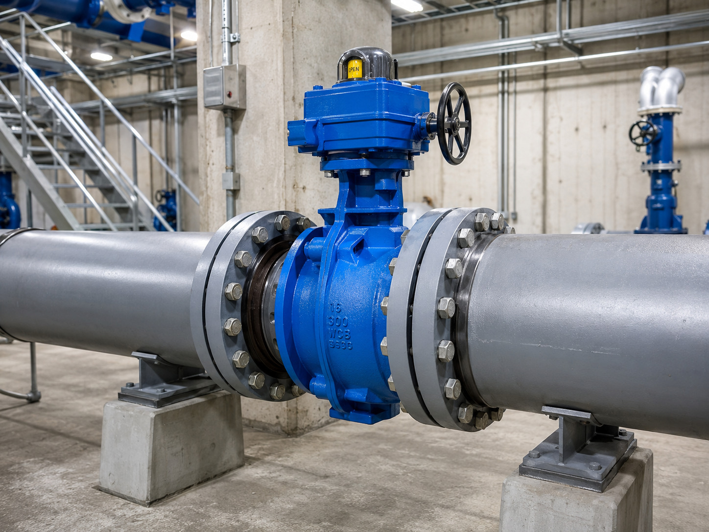
A butterfly shut off valve is a reliable isolation choice when its seat design, pressure-temperature rating, materials, body style, and operator are matched to the actual line conditions and required leakage limit. Its quarter-turn action makes it compact and fast, but a handle that reaches “closed” does not by itself prove that the seat can hold the maximum differential pressure.
This distinction matters in water, HVAC, utility, and process piping. A valve selected only by pipe size may fit between the flanges yet leak, damage the liner, stall the actuator, or create a pressure surge. Start with the shutoff duty, then select from an industrial butterfly valve range that can document the required configuration and tests.
Can a Butterfly Valve Provide Reliable Shutoff?
Yes, a butterfly valve can provide reliable shutoff when the complete valve assembly is rated and tested for the intended isolation duty. The circular disc turns approximately 90 degrees: parallel to the flow path when open and across the bore when closed. In the closed position, the disc edge loads the seat to form the pressure boundary.
The useful engineering definition is broader than “a quarter-turn valve.” A butterfly shut off valve is an isolation assembly whose body, disc, shaft, seat, seals, and operator must work together at the specified differential pressure, temperature, flow direction, and leakage limit.
Do not treat “tight shutoff,” “no visible leakage,” and a named leakage rate as interchangeable promises. The purchase specification should state the test standard, test medium, test pressure, test direction, holding time, and acceptance criterion that the project requires.
How the Disc, Seat, and Stem Create Isolation
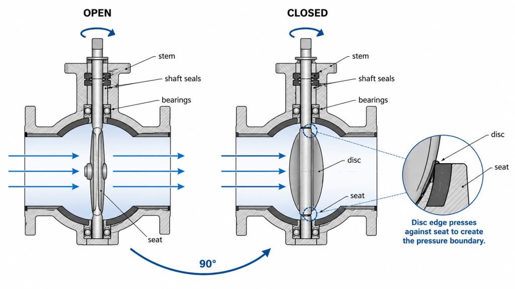
The disc stops the flow, but the seat and stem system determine whether the valve remains tight and operable. The seat seals around the disc perimeter, shaft seals prevent external leakage, and bearings keep the disc aligned as pressure and torque change.
In a concentric valve, the stem passes through the disc centerline and the disc contacts the resilient seat during movement. This suits many water and HVAC duties, but repeated throttling, abrasive particles, or excessive temperature can accelerate wear.
Offset designs change that contact geometry. A double-offset valve reduces rubbing as the disc leaves the seat; a triple-offset design creates a cam-like action and is commonly paired with metal seating for severe service. Geometry alone does not guarantee performance: the seat rating and leakage test still control the shutoff claim.
Set the Shutoff Duty Before Choosing the Valve
Define the required isolation result before choosing a body style, seat, or actuator. The following inputs turn a vague request for “a butterfly valve” into a specification that a manufacturer can evaluate and test.
| Required input | What to state | Risk if omitted |
|---|---|---|
| Media | Fluid name, concentration, suspended solids, particle character, and cleaning chemicals | Swelling, corrosion, abrasion, or solids trapped at the seat |
| Pressure | Normal, design, and transient pressure; maximum differential pressure at closure | Seat leakage, excess torque, or an underrated pressure boundary |
| Temperature | Normal range, startup or cleaning extremes, and cycling | Loss of seat elasticity or reduced pressure capability |
| Shutoff result | Allowable leakage, test standard, medium, pressure, duration, and direction | “Closed” position accepted without proving isolation |
| Piping interface | Size, flange standard and class, pipe bore, orientation, and available face-to-face space | Bolt-pattern mismatch, disc interference, or poor centering |
| Operation | Manual or automated duty, cycle frequency, closing time, fail position, and feedback | Actuator stall, damaging surge, or incorrect fail action |
Maximum differential pressure and leakage acceptance are decisive. Line pressure alone does not state the load on the closed disc, and the word “zero” is not a test method.
Match the Valve Design to the Service
Match the valve by sealing geometry, wetted materials, body style, and operator rather than by diameter alone. Each choice answers a different failure risk.
Choose the sealing geometry
Use a resilient-seated concentric design for compatible general service where economical tight closure is the priority. Consider double-offset construction when reduced rubbing, higher differential pressure, or frequent operation justifies it. Evaluate triple-offset, metal-seated construction when temperature, abrasion, or the pressure-temperature envelope rules out a soft seat.
Check every wetted material
Review the body, disc, stem, seat or liner, shaft seals, bushings, and coating against the media and temperature. A stainless-steel disc does not correct an incompatible elastomer, and the body rating does not prove the seat can seal at the same condition.
RUITO’s published scope includes DN25–DN3000 and PN10–PN25 configurations, with wafer, lug, and flanged bodies; multiple iron, steel, and duplex options; and EPDM, NBR, PTFE, FKM, or metal seating. Not every size, material, pressure, and temperature can be combined, so the selected data sheet must confirm the exact configuration.
Select the body style by piping duty
A wafer body is compact between two flanges. A lug body allows each flange to be bolted independently, but dead-end use is acceptable only when the exact valve is rated for the pressure and direction. A flanged body adds rigidity in larger permanent installations. Use the maintenance plan and end-of-line duty when making the lugged-versus-wafer decision.
Know When a Butterfly Valve Is the Wrong Shutoff
A butterfly valve is the wrong default when the disc obstruction or seat exposure conflicts with the process. Stop and compare another valve type when any of these conditions applies:
- The line must be pigged or swabbed, because the disc and shaft remain in the bore even when fully open.
- The media contains heavy, abrasive, stringy, or settling solids that can cut the seat, pack around the disc, or raise operating torque. A purpose-built eccentric or lined design may work, but a general-service soft seat should not be assumed suitable.
- The required pressure-temperature point or leakage limit is outside the seat rating, even if the body has a higher rating.
- One side of the pipeline will be removed under pressure and the valve has no documented dead-end rating for that direction.
- The valve will spend long periods near a small opening where high local velocity, vibration, cavitation, or disc-edge wear may occur. If isolation and control share one valve, review the butterfly valve flow characteristics across the intended operating range.
Butterfly valves are not limited to clean water, but solids content, particle behavior, flow regime, and seat design must be evaluated rather than reducing media selection to “liquid or gas.”
Where Butterfly Shutoff Works Best
Butterfly shutoff works best in larger lines where compact installation, low installed weight, and quarter-turn operation are valuable. Common duties include cooling-water headers, HVAC loops, municipal water transmission, filter isolation, pump-station manifolds, and compatible process utilities.
The same application name can hide different media. In water and wastewater systems, a resilient seat may suit treated water, while raw water with grit needs more attention to disc, coating, and seat wear. Abrasive sludge or stringy solids may favor a full-bore alternative.
Location also changes the specification. A buried valve may need an extension stem and protected gearbox; an outdoor actuator needs a suitable enclosure; a confined plant room makes access and removal clearance decisive.
Size the Operator and Control Closure Time
Size the operator for the highest required torque across the full service envelope, then set a closing time the piping system can tolerate. Required torque can change with differential pressure, seat friction, fluid velocity, temperature, deposits, cycle history, and flow direction. A catalogue torque measured under one condition is not automatically the correct actuator torque for another.
For manual operation, confirm that the lever or gearbox lets the operator reach full travel without excessive force and provides a trustworthy position indication. For automated service, specify available power or air pressure, on-off or modulating duty, cycle rate, fail-open or fail-closed action, travel stops, position feedback, and the required environmental or hazardous-area rating.
Fast quarter-turn capability does not mean the valve should close instantly. The U.S. Department of Energy explains that water hammer depends in part on fluid-velocity change and valve operating time; rapid closure produces a pressure wave. For liquid lines, use a transient analysis or the project’s closure profile instead of choosing the shortest actuator time.
Verify Shutoff Before the Valve Enters Service
Verify shutoff through document review, factory acceptance, and installed functional checks. Each stage catches a different class of error.
First, compare the approved data sheet and drawing with the order: size, rating, face-to-face dimension, flange drilling, bore clearance, flow direction, materials, seat rating, actuator, and leakage requirement. Confirm that certificates and test records identify the supplied batch or serial number.
Second, keep shell testing separate from seat testing. ISO 5208:2015 distinguishes pressure-boundary integrity from closure tightness and structural adequacy of the closing mechanism. Passing a shell test therefore does not prove that the closed seat meets the required leakage acceptance. RUITO’s published quality plan includes separate hydrostatic shell and seat-leakage checks with traceable test deliverables; the applicable procedure and acceptance values should be agreed for the order.
Third, protect the tested valve during installation. Check that the flanges are clean, parallel, and correctly spaced; center the valve; verify open-disc clearance; follow the fastening sequence; and use flange gaskets only when the instructions call for them. Before pressurizing, cycle the valve without obstruction and confirm its indications. The wafer butterfly valve installation checks provide a focused review.
Commission under controlled conditions. Confirm travel stops, actuator direction, fail action, feedback, and closing time; then check external and seat leakage at the agreed condition. Record the results so maintenance can distinguish installation drift from valve wear.
Make the Isolation Duty Explicit
Reliable butterfly-valve shutoff begins with a defined duty, not a product label. State the media, pressure-temperature envelope, maximum differential pressure, allowable leakage, piping interface, operating method, closing time, and records. Confirm that the exact seat, disc, body, and actuator combination is rated and tested for those conditions.
RUITO can review your line data, drawings, material requirements, and test documentation before quotation. For a project-specific recommendation or RFQ, contact the RUITO engineering team with your service conditions and required shutoff acceptance.
Frequently Asked Questions
Can a butterfly shut off valve also throttle flow?
Yes, some butterfly valves can throttle flow, but they must be sized for the control range rather than selected only by pipe diameter. Check the Cv curve, pressure drop, minimum operating angle, cavitation or noise risk, actuator resolution, and seat wear.
Which seat material is best for water service?
There is no universal best seat material for every water line. EPDM is widely used for compatible water and HVAC service, but temperature, disinfectants, oil contamination, pressure differential, approvals, and cleaning chemicals still require review.
Is every lug butterfly valve suitable for dead-end service?
No, lug construction alone does not guarantee dead-end capability. The manufacturer must rate the size, pressure, direction, lug design, and flange arrangement for that duty. Put the requirement in the order and approved data sheet.
Does a closed position indicator prove tight shutoff?
No, a closed indicator proves position, not seat tightness. Misadjusted stops, seat damage, debris, disc misalignment, or insufficient actuator torque can leave the indicated valve leaking. Verify isolation with the specified seat test or an approved in-service method.