
A reliable pneumatic actuator butterfly valve is selected as one package: define the valve service, size the actuator at the worst operating point, set the required fail position, and specify the controls and acceptance evidence. If any one of those decisions is missing, a valve that fits the pipe can still stall, move to the wrong position on a trip, or fail to report its actual position to the control system.
This guide gives engineers and technical buyers a practical sequence for specifying the complete assembly. If the valve body has not yet been selected, start with the available industrial butterfly valve configurations and then match the actuator to the chosen valve rather than choosing both from pipe size alone.
How the Valve and Actuator Work as One Package
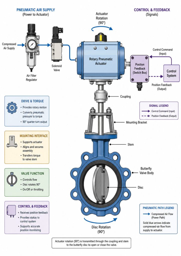
The assembly uses compressed air to create rotary torque, which turns the butterfly valve stem and disc through approximately 90 degrees. In a rack-and-pinion actuator, air moves pistons whose racks rotate a pinion. Other rotary mechanisms may produce a different torque curve, but the engineering task is the same: the actuator must deliver enough torque at every critical point in the valve stroke.
The valve and actuator perform different jobs. The valve body, disc, stem, and seat determine pressure containment, media compatibility, flow capacity, and shutoff. The actuator provides motion and torque. A mounting flange, bracket, and coupling transfer that torque, while controls and accessories tell the package when to move and confirm what it actually did.
This distinction matters because a suitable valve does not automatically make a suitable automated package. The actuator can fit mechanically yet be too weak at the available air pressure, or it can move the valve correctly during normal operation but not reach the required safe position after a loss of energy.
Define Valve Service Before Choosing the Actuator
You must select the valve for the real process duty before calculating actuator size. Begin with media composition, solids or crystallization risk, minimum and maximum temperature, maximum line pressure, maximum differential pressure, normal flow, and whether the valve will isolate or modulate.
Choose the body style for the piping function
Wafer bodies are compact and economical for many between-flange installations. Lug bodies may support one-sided piping removal or dead-end service, but only when the specific design has a stated dead-end rating. Flanged bodies can provide a more robust connection for large sizes or heavier pipe loads. Use a detailed lugged-versus-wafer selection check when maintenance isolation or end-of-line duty is part of the requirement.
Confirm the flange standard, face-to-face dimension, pipe bore, gasket arrangement, and disc clearance. A matching nominal size does not prove that the open disc will clear the pipe, liner, or adjacent fitting.
Select every wetted material, not only the body
Specify body, disc, stem, seat or liner, shaft seals, and any wetted fasteners. The seat has a direct effect on both chemical compatibility and operating torque. An elastomer that swells in the fluid can increase torque before it begins to leak; a hard or damaged seat can produce a different failure pattern. Temperature limits must therefore be checked with media, pressure, and cycling frequency together.
Decide whether a butterfly valve suits the control task
A butterfly valve is a strong choice for compact automated isolation and many moderate throttling duties. It is a weaker choice when the process needs very fine control over a wide range, operates under severe cavitation or noise conditions, or spends most of its time close to the seat. In those cases, review a characterized butterfly valve or another control-valve design before automating a line-size valve.
Size the Actuator for the Worst Operating Point
The actuator must meet the valve torque requirement at the lowest guaranteed air pressure and the most demanding valve condition. Do not compare a catalog actuator torque at nominal shop air with a generic torque value based only on valve diameter.
Ask the valve supplier for the applicable seating, unseating, running, and dynamic torque data. The governing value can change with disc position, differential pressure, seat material, temperature, flow direction, and media deposits. Then ask the actuator supplier for output torque across the full stroke at the minimum pressure that can actually reach the actuator after regulator and line losses.
For a double-acting actuator, verify torque in both directions. For a spring-return actuator, verify the air stroke and the spring stroke separately: spring compression changes the available output along the travel. Apply any design margin to a documented torque basis and stated service conditions rather than adding an unexplained percentage to an unknown value.
ISO 5115:2023 treats a part-turn actuated valve as an assembly of the valve, actuator, and, when required, the mounting kit. Its scope is a useful procurement reminder: sizing and selection responsibilities belong to the complete package, not to three independent catalog items.
Before approval, the calculation record should show:
- Valve torque basis, including size, seat, differential pressure, temperature, and direction of operation
- Minimum, normal, and maximum actuator supply pressure
- Actuator output at the relevant points in both the air and spring strokes
- Required fail direction, stroke time, and operating frequency
- Design margin and the service condition it is intended to cover
Choose the Fail Position from the Process Hazard
The required safe state must be defined from the process consequence, not from a preference for single- or double-acting hardware. Decide what the line should do after loss of instrument air, loss of electrical power, and loss of the control signal; these are separate events and can produce different results.
The following matrix turns the process decision into an actuator and control requirement.
| Process requirement | Typical package approach | What must be proved |
|---|---|---|
| Stop flow after loss of air | Spring-return, fail-closed assembly | Spring torque closes the valve at maximum differential pressure |
| Preserve cooling or relief flow after loss of air | Spring-return, fail-open assembly | Spring torque opens the valve against the governing load |
| Move by air in both directions | Double-acting actuator | Opening and closing torque are adequate at minimum air pressure |
| Hold position during an air disturbance | Engineered double-acting circuit with suitable reserve or lock-up arrangement | Hold time, leakage rate, control logic, and recovery behavior are tested |
The important conclusion is that “double acting” does not by itself guarantee fail-in-place. Internal leakage, external leakage, process torque, and the solenoid circuit can allow movement after air loss. Likewise, a spring-return actuator does not prove fail-closed until the actuator orientation, coupling, solenoid de-energized state, and spring torque have all been verified on the assembled valve.
Document the cause-and-effect logic in plain language. For example: “On loss of 24 VDC to the solenoid, the valve shall vent and travel closed; the closed limit switch shall confirm position to the PLC.” That statement is testable. “Provide fail-safe actuator” is not.
Match Accessories to On-Off or Modulating Duty
The accessory package must match the required command, feedback, air preparation, and operating speed. A basic on-off assembly commonly needs a solenoid valve, open and closed position switches, an air filter regulator, and suitable tubing and fittings. Add a manual override only when the operating procedure can control the risk of local movement.
For modulating duty, add a positioner compatible with the control signal and confirm whether independent position feedback is required. Select the valve from its flow coefficient at the expected opening angles, not its line-size capacity at full open. The butterfly valve Cv curve should place minimum, normal, and maximum flow within a usable control range. For formal control-valve calculations, apply the relevant sizing method under the ISA75.01 control valve sizing framework.
Stroke time is a package result, not an actuator label. It depends on actuator volume, supply pressure, tubing bore and length, solenoid flow capacity, exhaust restriction, speed controls, valve load, and temperature. State the required opening and closing times, then verify both on the assembled valve. Closing faster is not always better because rapid isolation can increase pressure surge in liquid systems.
Also specify the environmental and electrical conditions: ambient temperature, outdoor or washdown exposure, enclosure protection, hazardous-area classification, voltage, signal type, cable entry, and instrument-air quality. The valve may be compatible with the process while an exposed solenoid, limit switch box, or actuator seal is not compatible with the installation environment.
Verify the Mechanical Interface and Installation
Mechanical compatibility requires the mounting flange, drive connection, bracket, and coupling to transmit torque without misalignment or lost motion. ISO 5211:2026 defines attachment flange dimensions, driving component dimensions, and reference interface torque values for part-turn actuators. It does not replace valve torque sizing, and its published scope excludes the attachment of the intermediate support to the valve.
That boundary is practical. An ISO-pattern flange can match while the stem square, key, coupling engagement, bracket stiffness, or actuator orientation is wrong. Require an approved general arrangement drawing that identifies the valve stem, coupling, bracket, actuator model, mounting orientation, access space, and total assembled height.
During installation, keep the valve disc slightly open only as permitted by the installation instructions, center the body between mating flanges, and confirm disc clearance before tightening. For projects based on API requirements, align the purchase document with an API 609 butterfly valve specification and state body style, shutoff direction, dead-end duty, and mating flange details instead of writing only “API 609 compliant.”
After assembly, set the mechanical stops against the valve’s correct open and closed positions. Do not use the actuator stop to force a damaged or misaligned disc deeper into the seat. Cycle the package without process pressure first, then repeat the functional test under the approved site conditions.
Convert the Specification into Acceptance Evidence
A purchase specification is complete only when every important requirement has a corresponding approval or test record. This closes a common gap between a technically correct RFQ and a package that can be accepted at the factory or commissioned on site.
Send these operating inputs with the RFQ:
- Media, concentration, solids content, and any cleaning or flushing fluid
- Minimum, normal, and maximum pressure and temperature
- Maximum differential pressure in both flow directions
- Pipe size, flange standard, pipe bore, and required body style
- Isolation or modulating duty, flow data, and shutoff requirement
- Cycle frequency, required stroke time, and required fail position
- Minimum, normal, and maximum air pressure plus air-quality limits
- Solenoid voltage, command signal, feedback signals, and control-system interface
- Ambient conditions, hazardous-area requirements, manual override, and documentation standard
The approval and inspection package should then connect those inputs to evidence.
| Requirement | Evidence to approve or witness |
|---|---|
| Valve suitability | Data sheet, material list, pressure-temperature rating, and approved drawing |
| Actuator sizing | Valve torque basis and actuator output table at minimum air pressure |
| Fail action | Cause-and-effect statement, solenoid state, orientation, and loss-of-energy functional test |
| Mechanical fit | Mounting interface, stem and coupling drawing, bracket details, and disc-clearance check |
| Shutoff | Referenced test standard, test pressure and medium, direction, duration, and acceptance result |
| Control integration | Switch setting, position feedback, signal calibration, and measured stroke time |
| Traceability | Nameplate, serial or lot reference, material records, and final release documents |
The evidence should be specific to the supplied configuration. RUITO’s published butterfly valve documentation can include a material certificate, dimensional inspection report, torque test log, hydrostatic test chart, leakage certificate, and pre-shipment release records. Its stated range includes wafer, lug, and flanged options from DN25 to DN3000 and PN10 to PN25, with multiple body, disc, and seat materials; the approved data sheet must still identify the exact limits of the ordered model. For media selection, verify the final combination against the project conditions and the detailed butterfly valve seal selection criteria.
At factory acceptance, test commands and feedback as a loop rather than as isolated components. Command open, confirm the physical disc position and open switch, command closed, confirm the closed switch and leakage result, then simulate the specified loss-of-energy condition. A package passes only when motion, final position, feedback, timing, and shutoff all agree.
Get the Complete Package Right
A pneumatic actuator butterfly valve performs reliably when the process duty, valve construction, torque basis, fail logic, accessories, mounting interface, and acceptance tests describe the same assembly. Treating those items separately creates gaps that usually appear during commissioning, when correction is slowest and most expensive.
If you are preparing an RFQ, send the service conditions, valve standard, flow or shutoff duty, air-supply range, fail position, control signals, and required documents. The RUITO engineering team can review the complete package and provide a configuration for approval through our project contact page.
Frequently Asked Questions
Can a manual butterfly valve be retrofitted with a pneumatic actuator?
Yes, but only after checking valve condition, operating torque, stem dimensions, mounting interface, disc clearance, and the load capacity of the mounting kit. A custom bracket and coupling may solve dimensional fit, but they do not correct a worn seat, bent stem, or missing torque data.
What determines the opening and closing time?
Stroke time depends on actuator volume, available pressure, tubing, solenoid flow capacity, exhaust restriction, speed-control settings, valve torque, and temperature. Specify separate opening and closing times and verify them on the assembled package instead of accepting a catalog value for the bare actuator.
How do you confirm the valve rotation and fail direction?
Confirm them on the approved assembly drawing and by a functional test. Mark the disc position, apply and remove the specified air and electrical signals, and verify that the physical valve position, local indicator, limit switches, and PLC feedback all agree.
Is a manual override always necessary?
No. Add one when operating and maintenance procedures require local movement during loss of utilities, and control the risk of moving the valve against process pressure or an active automatic command. The override type and interlock arrangement must suit the actuator and site procedure.