
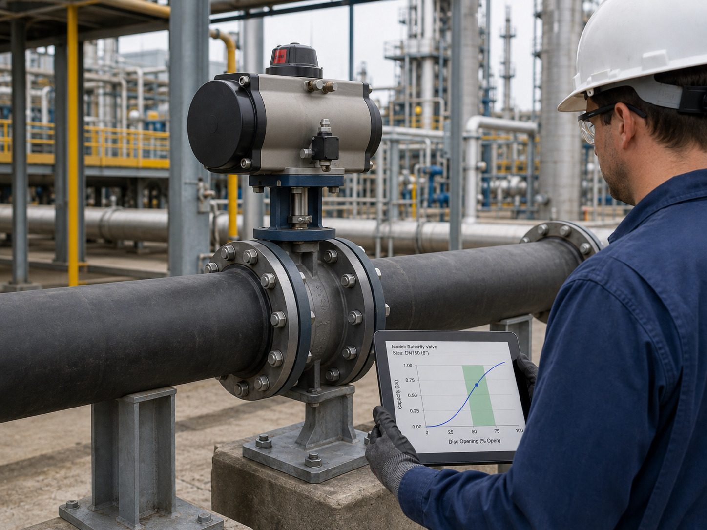
A butterfly valve Cv curve shows the flow coefficient available at each disc angle, so you can match valve capacity to minimum, normal, and maximum operating conditions instead of sizing from the full-open value alone. The curve is useful only when it belongs to the exact valve design and when you combine it with the pressure drop available across the valve.
This distinction matters in modulating service. A line-size valve may pass maximum flow easily yet spend normal operation near closed, where small position changes can produce an unstable response. The opposite error leaves the valve near fully open with no remaining capacity margin. A proper review of butterfly valve flow characteristics prevents both outcomes.
What a Butterfly Valve Cv Curve Actually Shows
A butterfly valve Cv curve plots valve capacity against disc opening, usually from the closed position to 90 degrees open. Cv is the number of U.S. gallons per minute of 60°F water that passes through the valve with a pressure drop of 1 psi at a stated opening.
The curve is nonlinear because the disc does not expose flow area in direct proportion to shaft rotation. Disc profile, shaft obstruction, seat geometry, body bore, offsets, and pressure recovery all influence the result. Consequently, 50% travel does not mean 50% of full-open Cv.
Keep these quantities separate when reading a graph or table:
| Quantity | What it means | What it does not prove |
|---|---|---|
| Disc angle | Mechanical position of the disc | Actual flow percentage |
| Percent travel | Actuator movement relative to full stroke | Equal increments of Cv |
| Cv at angle | Capacity under the Cv test convention | Installed flow at that position |
| Cv/Cv90 | Normalized capacity for that exact valve | A universal curve for other designs |
| Installed flow | Result of valve Cv and actual system pressure drop | Inherent valve behavior alone |
The critical engineering point is simple: a Cv curve is a capacity curve, not automatically a flow-percentage curve.
Read Angle, Travel, Cv, and Flow Separately
Read the horizontal axis first, confirm its opening convention, and then use the vertical axis exactly as labeled. Some charts show degrees open, others show percent travel, normalized Cv, or percent of maximum flow. Treating those labels as interchangeable can shift the selected operating point.
A 45-degree disc position is half of a 90-degree rotary stroke, but the Cv at that position must come from the named curve. Actual flow then depends on pressure drop:
Q = Cv × √(ΔP / SG)
Therefore, flow ratio equals Cv ratio only if the liquid specific gravity and pressure drop across the valve remain constant. In a real pumping or process system, valve pressure drop usually changes as total flow and piping loss change. Reading Cv/Cv90 as Q/Qmax without checking that condition is a common sizing error.
Do not extrapolate beyond published angles or copy a normalized curve to another size. If a project requires a position between adjacent data points, use interpolation only as a preliminary estimate, identify it as such, and obtain a confirmed value before approval.
Calculate Required Cv at Every Operating Point
Calculate the required Cv for minimum, normal, and maximum flow, then map each result to the model-specific curve. For a non-vaporizing turbulent liquid used in preliminary sizing:
Cv required = Q × √(SG / ΔP)
Here, Q is liquid flow in U.S. gpm, SG is specific gravity at flowing temperature, and ΔP is the pressure drop in psi allocated to the valve. ISA’s valve-sizing primer explains this Cv convention and the basic liquid relationship. A detailed butterfly valve pressure-drop calculation can then check the selected opening.
Use the actual valve pressure drop at each operating case, not the pump discharge pressure or total system differential. Account for static head, pipe and equipment losses, and downstream pressure requirements before assigning ΔP to the valve.
Record the results in one worksheet:
| Operating case | Required inputs | Curve result | Decision check |
|---|---|---|---|
| Minimum flow | Qmin, SG, available ΔP | Cv required and disc angle | Stable low-flow control |
| Normal flow | Qnormal, SG, available ΔP | Cv required and disc angle | Useful control travel |
| Maximum flow | Qmax, SG, available ΔP | Cv required and disc angle | Capacity margin and acceptable loss |
If a calculated point falls between published values, keep both surrounding curve points in the review. That makes the interpolation and its uncertainty visible.
Why There Is No Universal Butterfly Valve Cv Curve
There is no universal butterfly valve Cv curve because the coefficient belongs to a specific hydraulic geometry, not just a nominal pipe size. Two valves with the same DN and pressure class can have different disc thicknesses, shaft diameters, seat profiles, offsets, and internal bores.
Even within one product family, Cv can change with size or configuration. A resilient-seated concentric valve should not inherit the curve of a double-offset or triple-offset valve. A generic online chart may help with early screening, but it cannot approve a purchase or a control loop.
RUITO butterfly valve configurations include concentric, double-offset, and triple-offset designs with different seat, disc, body, and connection options; project documentation can include performance curves. That is why a curve request must identify the ordered configuration rather than ask only for “the DN200 butterfly valve Cv.”
Connect the Inherent Curve to the Installed System
An inherent Cv curve describes the valve under controlled pressure-drop conditions; the installed flow characteristic includes the rest of the system. As flow rises, losses through pipe, fittings, strainers, heat exchangers, and other equipment usually rise as well. The pressure drop left for the valve can therefore change across its stroke.
This is why a visually smooth Cv curve can still produce a compressed or distorted installed response. An oversized valve may control normal flow near the closed end, while an undersized valve can remain near wide open and consume excessive pressure drop at peak demand.
Cv and K also answer different questions. Cv relates flow capacity to valve pressure drop, while K represents component loss relative to velocity head. Use the butterfly valve K-factor method when building a full piping-loss model, but use the K value for the actual disc angle and geometry.
For gas, steam, non-Newtonian liquids, slurries, flashing, or possible choked flow, the simple liquid equation is not enough. IEC 60534-2-1 separates compressible and incompressible sizing and states that its basic incompressible equations are not intended for non-Newtonian fluids, mixtures, slurries, or liquid-solid transport. These services need the relevant fluid properties and valve-specific sizing factors.
Size the Valve from Three Curve Intersections
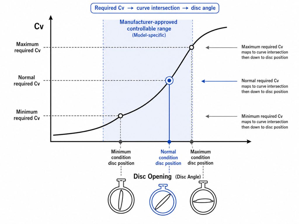
Size the valve by locating the minimum, normal, and maximum required Cv on the exact curve and checking the corresponding disc angles. A good selection keeps all three points within a controllable, manufacturer-approved operating range while meeting pressure-drop, velocity, noise, cavitation, shutoff, and torque limits.
Use this sequence:
- Define the valve duty: isolation, occasional throttling, or continuous modulation.
- Record fluid, temperature, specific gravity, viscosity, vapor pressure, and any solids or gas fraction.
- Establish minimum, normal, and maximum flow with upstream and downstream pressure for each case.
- Calculate the pressure drop actually available to the valve at each case.
- Calculate required Cv and find each intersection on the exact curve.
- Reject a size that forces normal operation into a poorly resolved end of the curve or leaves inadequate peak-flow margin.
- Check actuator torque, fail position, shutoff differential, seat compatibility, cavitation, noise, velocity, and nearby piping disturbances.
Do not accept “line size” as the complete sizing basis for modulating duty. Line size can be appropriate for isolation, but control service is governed by the required Cv range and the installed system response.
Validate the Curve Before Purchase Approval
Approve a curve only when its identity, basis, and revision match the valve being quoted. A smooth graph without configuration details is not procurement-grade evidence.
Request the following with the technical offer:
- Manufacturer, series, model, nominal size, pressure class, and end connection
- Concentric or offset design, body bore, disc, shaft, and seat configuration
- Flow direction and the definition of zero and 90 degrees
- Cv values at stated angles, not only a full-open coefficient
- Test, calculation, or simulation basis and the reference fluid
- Any reducer, expander, or piping-geometry correction applied
- Curve or table revision number tied to the quoted datasheet
- Minimum, normal, and maximum operating points marked on the curve
- Separate torque data for actuator selection; Cv does not replace torque analysis
Also run three consistency checks. Cv should not decrease as the valve opens unless the document explains an unusual convention. The curve must reach the quoted full-open value. The operating points in the sizing sheet must use the same units, valve configuration, and revision as the purchase specification.
If the supplier provides only one full-open Cv, you can evaluate isolation pressure loss but cannot validate modulating performance. Ask for Cv by angle or select a valve with documented part-travel data.
Make the Curve Part of the Valve Specification
The butterfly valve Cv curve becomes decision-grade only when it is model-specific, tied to real operating cases, and checked against the installed system. Separate angle from travel, Cv from flow percentage, and inherent capacity from installed response; then verify all three operating points before approving the size.
RUITO can review the medium, temperature, pressure range, minimum/normal/maximum flow, allowable valve pressure drop, piping interfaces, materials, and required documentation. To turn those inputs into a project-specific review, send RUITO your operating cases.
FAQ
What is a good Cv value for a butterfly valve?
A good Cv is the value that meets the required flow at the allocated valve pressure drop while placing the operating points in a usable part of the exact valve curve. A larger Cv is not automatically better because an oversized valve may control too close to closed.
Can I use a generic butterfly valve Cv table?
Use a generic table only for preliminary screening. Replace it with data for the exact series, size, disc, shaft, seat, pressure class, and opening convention before design or purchase approval.
Is percent open the same as percent flow?
No. Percent open describes mechanical travel, while percent flow also depends on the nonlinear Cv curve and the pressure drop available across the valve in the installed system.
Can I size gas or steam with the liquid Cv equation?
No. Gas and steam density changes through the valve, and compressible-flow sizing requires absolute pressures, temperature, gas properties, and valve-specific factors, including checks for choked flow.