
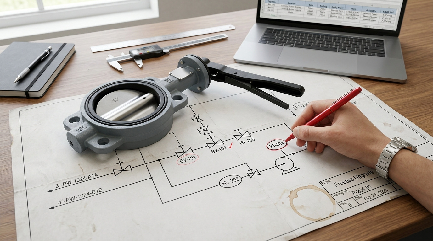
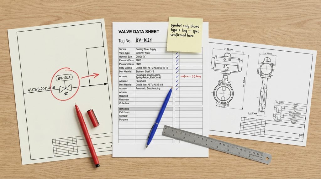
A butterfly valve P&ID symbol identifies a quarter-turn valve with a rotating disc, but the exact graphic must always be read together with the drawing legend, tag number, actuator notation, normal position, and valve data sheet. In a real project, the symbol tells you where the valve sits in the system and what function it is intended to perform, while the final valve details must be confirmed from the specification.
If you are checking a crowded P&ID before issuing an RFQ, the risk is not just misreading one small icon. You may also miss whether the valve is manual or actuated, normally open or closed, wafer or lug type, or suitable for the line class. This guide explains how to read the symbol correctly and how to connect it back to practical industrial butterfly valves used in water, HVAC, chemical, power, and general process systems.
What a Butterfly Valve P&ID Symbol Means
A butterfly valve P&ID symbol mainly shows that the pipeline uses a rotary disc valve for isolation, flow control, or automated shutoff. The symbol does not prove the valve size, seat material, pressure rating, end connection, or actuator torque by itself.
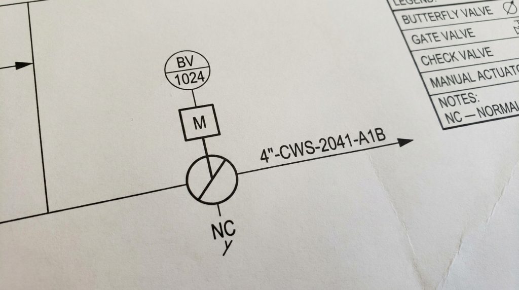
In many drawing systems, you may see two opposing open triangles, a circular valve body with a diagonal line, or a generic valve shape with a disc mark. These variations can all point to the same basic idea: a disc rotates inside the valve body, usually through 90 degrees from fully open to fully closed. When you are identifying a butterfly valve symbol in a P&ID diagram, the legend and tag system matter more than memorizing one universal icon.
What Does the Basic Graphic Show?
The basic graphic shows valve function, not full construction. It tells you that the valve is a butterfly type, usually chosen for compact face-to-face dimensions, fast quarter-turn operation, and efficient service in larger lines.
The disc mark is the key visual clue. Compared with a gate or globe valve, the butterfly valve does not rely on a rising stem or linear plug movement; it uses a rotating disc in the flow path. That is why the symbol often uses a diagonal or central line to suggest disc rotation.
Why Is the Legend the Final Authority?
The legend is the final authority because P&ID symbols are not drawn the same way in every company, region, or CAD library. ANSI/ISA-5.1, ISO 10628, ISO 14617, and ISO 15519 all support consistent diagram interpretation, but project standards may still define their own accepted symbol variants.
Before you approve a drawing, check the lead sheet or legend for these items:
- Valve symbol style and abbreviation rules
- Manual, pneumatic, electric, and hydraulic actuator symbols
- Normal position and fail position notation
- Connection or end-type notation
- Tag numbering structure and equipment schedule references
Key takeaway: treat the butterfly valve symbol as the entry point, then use the legend and valve schedule to confirm what the project actually requires.
How to Read Tags, Positions, and Actuators
The tag and actuator information often matter more than the symbol shape because they explain how the valve is operated and what it does in the control logic. A manual butterfly valve and a fail-closed automated butterfly valve may share the same base symbol, but they have very different design and procurement requirements.
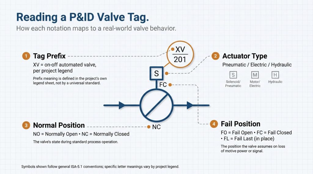
A tag such as BV, XV, MOV, or HV is not universal, so read it according to the project legend. In many projects, BV may mean butterfly valve, XV may identify an on-off automated valve, MOV may mean motor-operated valve, and HV may identify a hand-operated valve. The tag should connect the P&ID symbol to the valve list, line list, datasheet, I/O list, and maintenance records.
Can the Symbol Show Normal or Fail Position?
Yes, the symbol can show normal or fail position, but only if the drawing standard defines how that notation is used. NO and NC usually mean normally open and normally closed. FO, FC, and FL usually mean fail open, fail closed, and fail last or fail locked, depending on the project convention.
Normal position is not the same as live operating position. A P&ID normally shows the intended design state, not necessarily the actual real-time valve position in the plant. For live status, you need the control system, limit switches, position transmitter, or commissioning record.
How Do Actuator Notes Change the Meaning?
Actuator notes change the symbol from a simple valve item into part of an operating and control function. A pneumatic actuator may require instrument air, solenoid valves, limit switches, and fail-safe spring action. An electric actuator may require power supply, torque setting, local control, remote signal, and feedback contacts.
For part-turn valves, ISO 5211 is commonly used to define actuator mounting interfaces. The P&ID may only show “electric actuator” or “pneumatic actuator,” but the purchasing package must still confirm mounting flange, stem drive, torque margin, enclosure rating, control signal, and fail action.
How It Differs From Similar Valve Symbols
A butterfly valve symbol differs from similar valve symbols by pointing to rotary disc movement, while ball, globe, gate, and check valve symbols point to different internal mechanisms. This distinction affects operation speed, pressure drop, throttling suitability, installation space, and ordering accuracy.
If the symbol is misread, the procurement team may order the wrong valve type even when the line size and pressure class are correct. That is why P&ID review should compare the graphic, tag, service description, and datasheet instead of relying on one visual cue.
| Valve type | Main P&ID clue | Typical function | What to confirm before ordering |
|---|---|---|---|
| Butterfly valve | Disc or diagonal mark in valve symbol | Quarter-turn isolation or moderate control | Seat material, disc material, body pattern, actuator torque |
| Ball valve | Ball or quarter-turn valve symbol, often for tight shutoff | On-off isolation, often smaller or critical services | Full port or reduced port, fire-safe need, stem design |
| Gate valve | Gate-style symbol, usually linear motion | Full-open or full-closed isolation | Rising/non-rising stem, wedge type, pressure class |
| Globe valve | Globe/plug-style symbol | Throttling and regulation | Flow direction, trim, pressure drop, control duty |
| Check valve | One-way symbol or flow-direction cue | Backflow prevention | Swing, lift, dual-plate, cracking pressure, installation orientation |
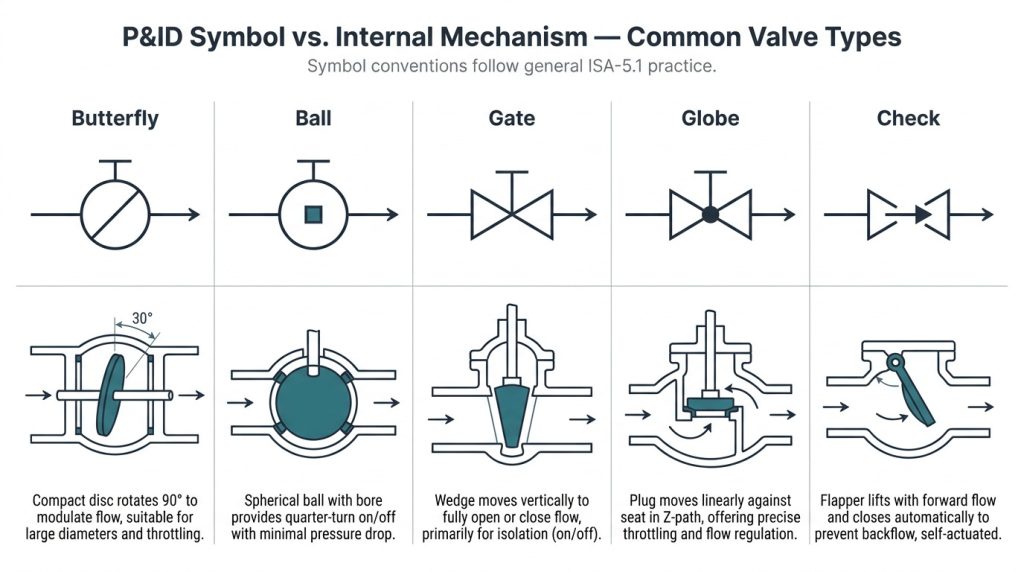
This table is a practical screen, not a replacement for the project legend. A custom drawing library may use modified symbols, especially in brownfield plants with older documentation.
What Makes It Different From a Ball Valve?
The main difference is the internal shutoff element. A butterfly valve uses a disc that remains in the flow path even when open, while a ball valve uses a bored ball that may offer full-bore or reduced-bore flow.
This difference affects pressure drop, size, weight, and cost. Butterfly valves are often attractive for larger water, cooling, HVAC, and general process lines. Ball valves may be preferred where tight shutoff, pigging, high pressure, or compact small-bore isolation is more important.
How Do You Avoid Confusing It With Check Valves?
You avoid confusion by checking the flow-direction logic. A check valve symbol is tied to one-way flow and backflow prevention, while a butterfly valve symbol represents an operated valve that can open, close, or modulate.
If a symbol includes an arrow, do not assume it is a check valve immediately. Some butterfly valves, especially eccentric or high-performance designs, may have a preferred pressure direction. Confirm the meaning in the legend and the valve datasheet.
What the Symbol Cannot Confirm About the Valve
The symbol cannot confirm the actual valve specification, so you should never order from the P&ID symbol alone. It must be matched with the valve schedule, line class, datasheet, actuator datasheet, and applicable standards.
This is where many drawing reviews fail. The P&ID may show “butterfly valve,” but the final hardware still depends on medium, pressure, temperature, shutoff requirement, flange standard, actuator mode, and installation constraints. A separate butterfly valve selection check is needed when the drawing is moving toward procurement.
| P&ID item to check | What it tells you | What it does not prove | Where to confirm |
|---|---|---|---|
| Base butterfly symbol | Valve type and location | Size, material, pressure rating | Valve schedule and datasheet |
| Tag such as BV or XV | Functional identity | Body pattern or seat type | Tag list and instrument index |
| Line size and class | Pipeline design context | Actual valve drilling or face-to-face | Piping class and valve drawing |
| Connection notation | Wafer, lug, flanged, or welded intent | Bolt length, dead-end rating, gasket limits | Manufacturer drawing and project spec |
| Actuator symbol | Manual, pneumatic, electric, or hydraulic operation | Torque margin, mounting interface, enclosure | Actuator datasheet and torque calculation |
| NO, NC, FO, or FC | Normal or fail state | Real-time valve position | Control narrative and commissioning record |
For flanged systems, ASME B16.5 applies to pipe flanges and flanged fittings from NPS 1/2 through NPS 24, but that does not mean every butterfly valve on the drawing automatically matches a specific ASME class. For butterfly valve hardware, API 609, MSS SP-67, EN 593, AWWA C504, or another project-specified standard may control design, testing, marking, and end connection details.
What Must Move From Drawing to Datasheet?
The datasheet must carry the items that the symbol cannot safely hold. These include nominal size, pressure class or PN rating, body material, disc material, stem material, seat material, leakage requirement, end connection, face-to-face standard, actuator type, fail position, accessories, and testing requirements.
For example, a soft-seated concentric butterfly valve in water service may use EPDM or NBR seats, while chemical service may require PTFE or another compatible liner. High-temperature or abrasive service may require metal seating or an eccentric design. The final limits must come from the valve drawing and datasheet, not from the icon.
Which Standards Help Define the Hardware?
Different standards answer different questions. ANSI/ISA-5.1 helps with instrumentation symbols and identification. ISO 10628 and ISO 14617 support graphical and diagram conventions. IEC 62424 becomes relevant when P&ID data is exchanged between engineering tools and process-control engineering tools.
Valve hardware standards answer another set of questions. API 609 covers butterfly valves such as double-flanged, lug-and-wafer-type, and butt-welding designs. MSS SP-67 covers butterfly valve dimensions, design, testing, and marking. API 598 and ASME B16.34 may be used for pressure testing requirements, where hydrostatic shell testing is commonly specified at 1.5 times the applicable pressure rating under defined conditions.
Where These Symbols Matter in Real Systems
Butterfly valve symbols matter most in systems where many similar valves appear close together and the cost of misidentification is high. Large water lines, cooling systems, HVAC loops, utility headers, chemical transfer lines, and power plant auxiliary systems often contain repeated isolation and control points.
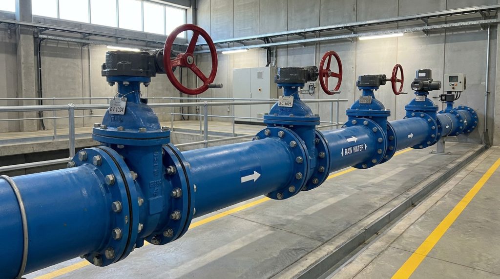
In water and wastewater treatment, for example, a wrong valve type or normal-position error can affect pump isolation, filter bypass, chemical dosing, sludge handling, or backwash sequencing. In chemical or power systems, the same mistake can affect interlocks, startup logic, maintenance isolation, or emergency shutdown planning.
When Is a Butterfly Valve a Good Fit?
A butterfly valve is often a good fit when you need compact construction, fast operation, and efficient flow through medium or large pipe sizes. It is commonly used for water, air, cooling water, HVAC, and many general process services.
It may not be the best fit where the line has very high pressure drop, severe cavitation risk, highly abrasive slurry, strict control accuracy, or service conditions beyond the seat material limit. In those cases, the P&ID symbol should push you to confirm the duty, not simply accept the valve type.
Why Does Symbol Clarity Affect Safety?
Symbol clarity affects safety because operators and maintenance teams use P&IDs to plan isolation, lockout, startup, shutdown, and emergency response. If a valve is shown as manual when it is automated, or normally open when it should be normally closed, the drawing can lead teams toward the wrong action.
The same applies to fail position. A fail-closed valve in a chemical feed line and a fail-open valve in a cooling water line may look similar at first glance, but their process consequences are very different.
Common Butterfly Valve P&ID Mistakes
The most common butterfly valve P&ID mistakes happen when the symbol is correct but the surrounding information is incomplete or inconsistent. A clean symbol is not enough if the tag, actuator note, line class, and valve schedule disagree.
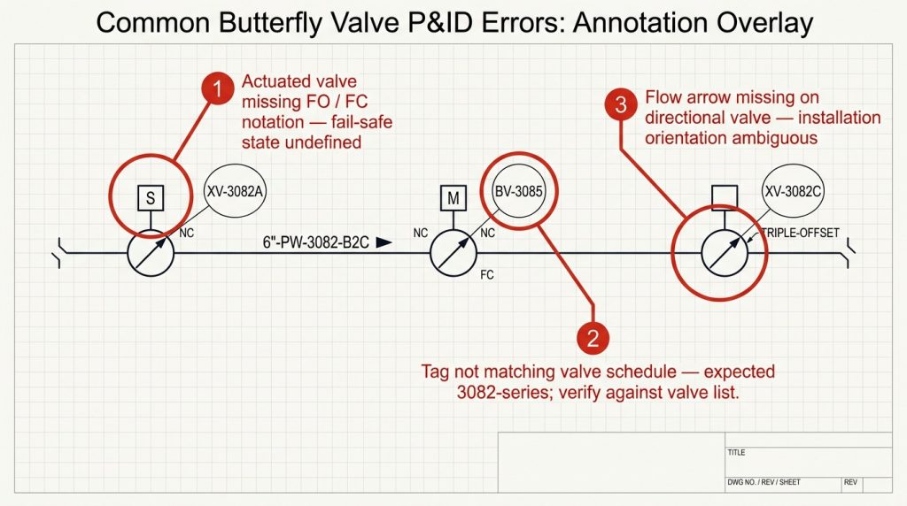
Many teams focus on the graphic and miss the coordination problem. During drawing review, compare the P&ID against the valve list, equipment layout, control narrative, and piping class. A separate check of butterfly valve P&ID layout errors can help when your drawing set has repeated valve symbols or copied details.
What Errors Cause Procurement Problems?
Procurement problems usually come from missing or conflicting specification details. The purchasing team may receive a tag number and line size but no seat material, actuator type, flange drilling, or shutoff requirement.
Watch for these errors before releasing the RFQ:
- Wafer valve shown where lug or flanged construction is required
- Actuated valve missing fail-open or fail-closed notation
- Manual valve shown without gear operator requirement on larger sizes
- P&ID tag not matching the valve schedule
- Line class based on ASME while the project requires EN or DIN flanges
- Flow arrow missing where the valve has a preferred pressure direction
What Errors Cause Operating Problems?
Operating problems usually come from unclear normal position, wrong fail state, or missing control logic. A valve may be physically correct but still wrong for the process if it fails in the wrong direction or sends no position feedback to the control system.
Also check whether the valve is intended for throttling. Butterfly valves can regulate flow in some applications, but they are not automatically suitable for all modulating duties. High velocity near the disc, cavitation, seat wear, and actuator hunting can appear if the valve is used outside its control range.
How to Review a P&ID Before Releasing It
The best review method is to treat the butterfly valve symbol as one item in a connected document set. You should verify the symbol, tag, duty, actuator, normal state, physical valve design, and procurement data before the drawing is released.
Use this short review sequence:
- Check the legend for the approved butterfly valve symbol.
- Confirm every tag appears in the valve schedule.
- Match line size, line class, and service description.
- Confirm manual, electric, pneumatic, or hydraulic actuation.
- Check NO, NC, FO, FC, or fail-last notation.
- Confirm wafer, lug, flanged, or butt-weld construction if relevant.
- Review seat, body, disc, and stem materials against the medium.
- Verify testing requirements such as API 598, EN 12266, ISO 5208, or the project ITP.
- Confirm the final valve drawing before purchase or fabrication.
This review prevents the symbol from becoming a false shortcut. A P&ID is a coordination drawing; it is not a dimensional manufacturing drawing and should not carry the full burden of valve selection.
Key takeaway: if the drawing tells you “what and where,” the datasheet and valve drawing must still tell you “exactly which valve and under what conditions.”
Conclusion
A butterfly valve P&ID symbol is useful because it gives you fast visual recognition of a quarter-turn disc valve in the piping system. To use it correctly, you need to read the symbol together with the legend, tag number, actuator note, normal and fail positions, line class, valve schedule, and datasheet. That extra check is what turns a simple drawing icon into a reliable engineering and procurement decision.
If you are reviewing a project drawing, preparing an RFQ, or checking whether the valve tags match the required service conditions, share the P&ID, valve list, medium, pressure, temperature, connection standard, and actuator requirements when you send your project details.
FAQ
Can I use one butterfly valve symbol for every drawing?
No, not safely. You can use a standard base symbol, but the final drawing must follow the project legend and show any required actuator, position, connection, or fail-state information.
What’s the best way to show an actuated butterfly valve?
The best way is to show the base butterfly valve symbol plus the actuator type, control tag, and fail position. If the actuator is electric, pneumatic, or hydraulic, that information should also match the instrument index and actuator datasheet.
How do I know if the symbol means wafer or lug?
You usually cannot know from the base symbol alone. Some projects show connection details on the P&ID, but many require you to confirm wafer, lug, flanged, or welded construction from the valve schedule and manufacturer drawing.
Can I use the P&ID symbol to order the valve?
No, the symbol alone is not enough for ordering. You need size, pressure class or PN rating, body and seat materials, end connection, face-to-face standard, actuator details, test requirements, and any project-specific documentation.
How do I know if the drawing uses ISA or ISO symbols?
Check the legend or lead sheet first. If the drawing does not identify the symbol standard, ask for clarification before issuing the valve list, because mixed symbol conventions can cause design review and procurement errors.