
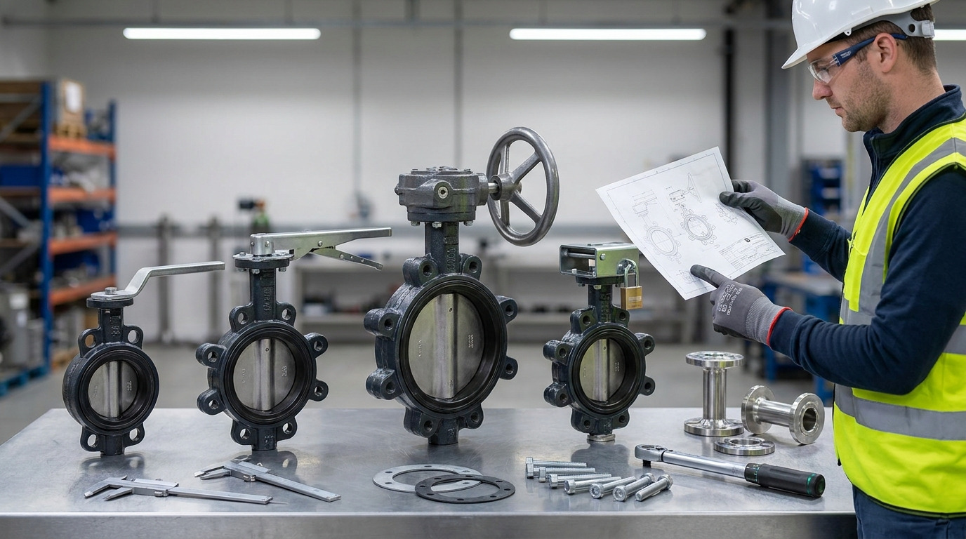
Choose butterfly valve handles by matching the required torque, operation frequency, position control, access space, environment, and future automation plan to the valve, not by handle material alone. For a butterfly valve, the handle is the operator’s direct connection to a 0-to-90-degree disc movement, so it affects safety, shutoff confidence, throttling accuracy, and maintenance access.
A common plant example is a cooling-water line where a small lever-operated valve feels easy during commissioning, but the same handle style becomes hard to move after pressure changes, scale buildup, or a larger valve size is introduced. The better direction is not simply “buy the strongest handle.” You need to decide whether the valve needs a lever, lockable handle, notched plate, gear operator, handwheel, or actuator-ready interface.
How Butterfly Valve Handles Affect Operation
A handle changes how safely and accurately the operator can turn the disc, even though it does not change the basic valve principle. A butterfly valve normally moves from fully closed to fully open in about 90 degrees, but the operating effort is not the same through the whole stroke.
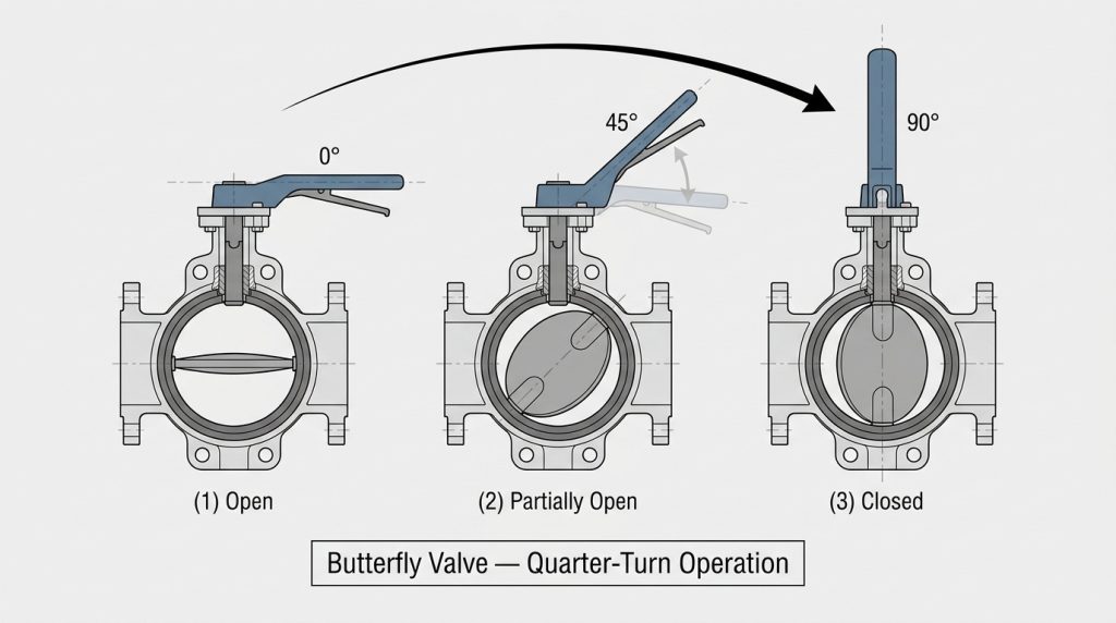
Breakaway torque is usually the first concern. This is the force needed to start moving the disc from rest, especially when the seat is compressed, the pressure differential is high, or the valve has been idle for a long time. Running torque is the force needed to keep the disc moving once it has started. If you only judge the handle by full-open movement, you may miss the most difficult part of operation.
How does a quarter-turn handle show position?
A lever handle usually gives a fast visual clue: parallel to the pipe often means open, and perpendicular often means closed. That rule is useful, but it must be verified against the valve design, stem orientation, and any position plate or stop arrangement on the actual valve.
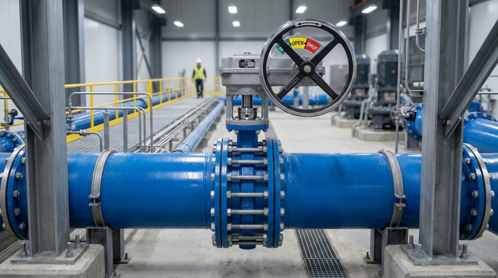
For gear operators and handwheels, position is normally shown by a pointer, dial, travel stop, or open/close marking rather than by the handwheel direction itself. The handle may rotate many turns while the disc still moves only 90 degrees, so the indicator becomes more important than the operator’s memory.
Why can handle feel mislead you?
Handle feel can mislead you because effort depends on pressure, seat friction, disc angle, and service condition. A valve that feels smooth on a bench can become difficult under line pressure, while a valve that turns easily may still fail to seal if the disc is not reaching the correct stop.
Do not use “easy to move” as the only sign of correct operation. Confirm the open and closed stops, the direction of operation, and the actual disc position on the valve drawing or data sheet. In critical isolation points, position indication and locking are often more important than handle comfort.
Lever, Grip, and Notched Plate Handles
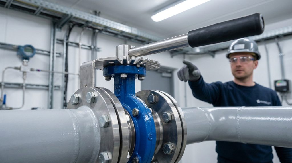
Lever handles fit valves that can be opened and closed with direct manual torque without putting the operator or the stem assembly at risk. They are common on small and many medium-size butterfly valves because they are simple, quick, compact, and easy to understand.
A lever handle often works with a notched plate or detent plate. The notches allow the operator to hold the disc at selected positions instead of relying on hand pressure. This makes the handle useful for isolation and coarse flow adjustment, but it should not be mistaken for precise control.
What makes a lever handle the right choice?
A lever handle is the right choice when the valve is operated occasionally, the torque is low enough for comfortable manual use, and the system does not need remote control or fine modulation. It also fits locations where operators need a quick open-close action and clear local position visibility.
Use a lever handle when these conditions line up:
- The valve can be moved safely by hand at maximum differential pressure.
- The valve is accessible from a stable working position.
- The process accepts quick quarter-turn operation.
- The notched plate can hold the intended intermediate positions.
- Locking, tamper supervision, or remote feedback is not required.
The practical boundary is not one universal DN size. A small valve in sticky or high-differential-pressure service can need more torque than a larger valve in clean, low-pressure water service. Final handle selection should be checked against the valve’s torque data, not only the nominal pipe size.
Where do stamped, cast, and aluminum handles differ?
Stamped handles are usually light and economical, but their stiffness and coating quality matter. They can be suitable for low-torque service, but they are not the best first choice where the operator may apply high force or where impact damage is likely.
Cast iron or malleable iron handles bring more rigidity and a heavier feel. They are often preferred where the handle must resist rough use, but coating and corrosion protection still matter. Aluminum handles reduce weight and can resist general atmospheric corrosion well, but they must still be checked for the service environment, coating system, and mechanical strength.
The better comparison is not “which material is best.” It is this: does the handle material, shape, coating, grip, and stop plate match the torque and environment of the valve?
Gear Operators and Handwheels
A gear operator is the right choice when direct lever force becomes unsafe, inconsistent, or too coarse for the duty. A geared butterfly valve reduces hand effort by adding mechanical advantage, but the tradeoff is slower travel and the need for a reliable position indicator.
When you are comparing a lever-operated valve with a butterfly valve with gearbox, focus on torque margin, frequency of operation, and how accurately the operator needs to stop at a position. Gearboxes are especially useful when the valve is larger, pressure differential is higher, or the operator must avoid sudden disc movement.
When should you move from lever to gearbox?
Move from a lever to a gearbox when the valve cannot be operated smoothly and safely by hand at the worst expected condition. Worst condition means maximum differential pressure, cold startup, dirty service, long idle periods, and any seat swelling or scale buildup that may increase torque.
A gearbox is also a better fit when the valve is used for repeated balancing or coarse throttling. It lets the operator make smaller position changes and reduces the temptation to force a long lever past the stop. However, if the service needs true automatic control, a manual gearbox may only be a temporary answer.
What does self-locking really mean?
Self-locking means the gear mechanism resists back-driving from line forces, so the disc is less likely to move because of flow torque. Worm gear operators are commonly used for this reason, but you should still confirm the gearbox rating, travel stops, and torque capacity for the actual valve.
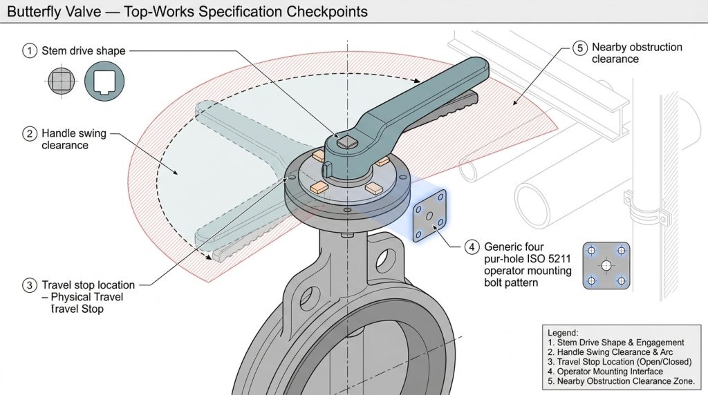
For actuator-ready valves, ISO 5211:2026 is an important reference because it specifies requirements for part-turn actuator attachments, including flange dimensions, driving component dimensions, and reference torque values for interfaces and couplings. That does not select the handle for you, but it helps prevent a poor match between the valve top works, gearbox, and future actuator.
Key takeaway: if the valve may later be automated, treat the manual operator and top mounting interface as part of the long-term specification, not just a temporary handwheel.
Handle Choice by Service Conditions
Service conditions should narrow the handle choice before appearance or price enters the discussion. Clean water, treated HVAC loops, wastewater, outdoor utility lines, chemical exposure, and buried service can all push the same valve size toward different operating hardware.
In water and wastewater treatment, torque can rise because of solids, deposits, corrosion, or long intervals between operation. AWWA C504-23 covers rubber-seated butterfly valves from 3 in. through 72 in. for raw water, potable water, wastewater, and reclaimed water, with a stated pH range of 6-12 and temperature range of 33 F to 125 F under its scope. Within that broad range, lever operation may fit smaller accessible valves, while gear operators or actuated packages often make more sense for larger or harder-to-reach duty.
For HVAC and district energy, the handle decision is often about repeatable balancing, access in mechanical rooms, and clear position reference. A notched lever may be enough for simple isolation or occasional balancing, but gear operation can be easier on larger chilled-water or condenser-water valves where small position changes affect flow distribution.
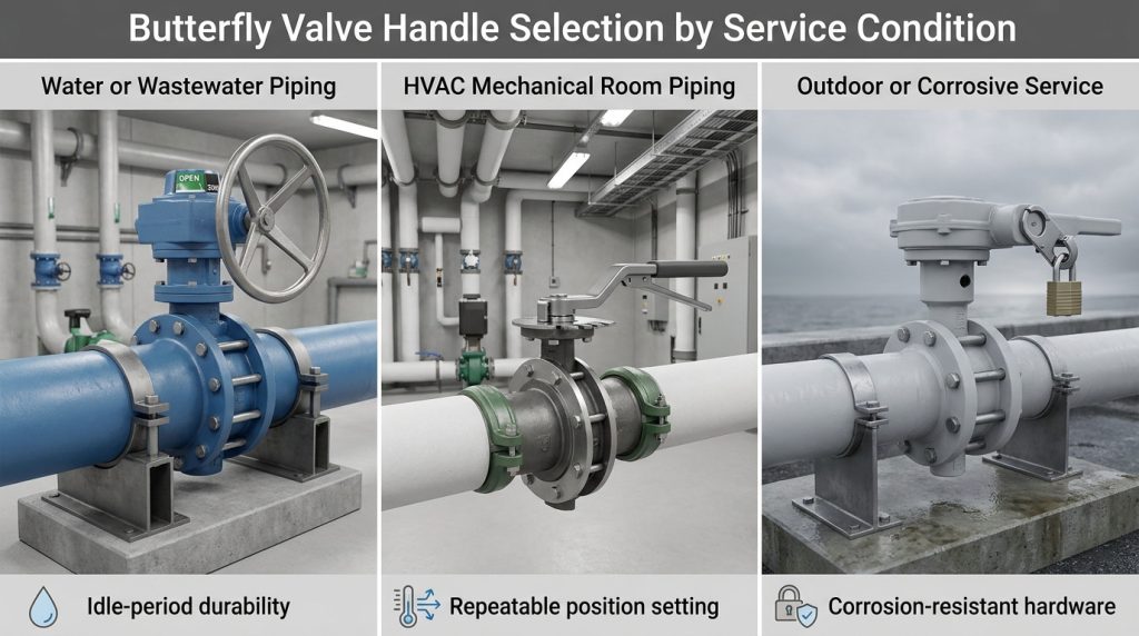
How do water and HVAC duties differ?
Water and wastewater service often puts more emphasis on durability, corrosion protection, and the ability to operate after long idle periods. If the valve sits open for months and then must close under pressure, breakaway torque matters more than the handle’s normal feel during routine checks.
HVAC service often puts more emphasis on repeatable partial opening and operator visibility. If a balancing point needs to be restored after maintenance, a handle with a clear notch plate, stop setting, or gear position indicator can save confusion. For automated flow control, the manual handle should not be used as a substitute for proper actuator sizing and feedback.
What changes in corrosive or outdoor service?
In corrosive or outdoor service, the handle system includes the handle, fasteners, stop plate, gear housing, coating, nameplate, and any locking device. A strong handle with weak fasteners or a poorly protected plate can still become unreliable.
Check whether the handle coating is suitable for the site atmosphere, whether stainless fasteners are needed, and whether the position markings will remain readable. For coastal, chemical, or buried applications, the manufacturer’s material and coating recommendations matter more than generic labels such as “heavy duty.”
Position Control, Locking, and Safety Signals
Position control matters because a handle can suggest where the disc is, but it does not always prove what the process is experiencing. This is especially important when the valve is used for throttling, fire protection supervision, restricted isolation, or any service where accidental movement creates risk.
A butterfly valve does not deliver linear flow just because the handle is 50 percent open. The disc remains in the flow path, and flow changes nonlinearly as the disc rotates. For many general butterfly valve designs, continuous modulation is commonly screened around the middle part of travel, often about 30 to 70 degrees open, while operation below about 20 to 30 degrees or above about 70 to 80 degrees needs closer review against the valve’s curve and service conditions. A deeper look at butterfly valve flow characteristics is useful when the handle position is being used to control flow instead of only open or close.
Can a handle be used as a position indicator?
Yes, a handle can be used as a basic position indicator, but only when the handle, stem, disc, and stop plate are correctly assembled and clearly marked. For routine isolation, this may be enough.
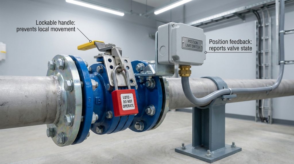
It is not enough when the valve position must be monitored remotely or documented for a safety function. In those cases, use a limit switch, position transmitter, supervisory switch, or actuator feedback device as required by the system design. The manual handle then becomes local operation hardware, not the only proof of valve state.
When do you need locking or supervision?
You need locking when unauthorized or accidental movement could interrupt service, bypass treatment, isolate safety equipment, or change a validated process setting. A lockable lever or lockable gear operator can hold the local setting, but the lock should match the plant’s lockout procedure and access rules.
You need supervision when someone must know the valve state without standing next to it. Fire protection, remote utility lines, automated systems, and critical isolation points may require electrical position feedback. A padlock prevents movement; it does not report movement.
How to Specify Handles Without Overspecifying
Good specifications define the operating result you need without locking the project into an unnecessary handle detail. If you specify only “manual handle,” you may get a low-cost lever where a gearbox is needed. If you specify every detail too tightly, you may block a better compatible operator from the valve manufacturer.
A practical handle specification should state the valve size, pressure class or PN rating, maximum differential pressure, medium, temperature, installation location, operating frequency, required position indication, locking requirement, and any future actuator plan. The final torque value should come from the valve data sheet under the stated service conditions.
What should a data sheet confirm?
A useful data sheet should confirm more than the handle material. It should show the required operating torque, operator type, opening direction, travel stops, handle or handwheel material, coating, position indication, locking option, mounting interface, and whether the valve is suitable for future actuation.
For projects using recognized valve standards, keep the boundary clear. API Standard 609 covers butterfly valve requirements for double-flanged, lug-and-wafer-type, and butt-welding-end designs, but it does not give a universal rule that one handle type fits a certain pipe size. As of July 2026, API Standard 609 10th Edition has been published and becomes effective on December 1, 2026, so project documents should state the applicable edition rather than leaving it vague.
What should be left to the valve drawing?
The valve drawing should confirm top works, stem shape, handle orientation, clearance envelope, gearbox mounting, travel stop location, and any interference with insulation, walls, pipe supports, or nearby equipment. This is where many handle problems become visible before the valve reaches the site.
Use the following table as a decision screen before you finalize the operator type.
| Handle or operator option | Best fit | Watch the risk | Final confirmation |
|---|---|---|---|
| Direct lever with notched plate | Fast local isolation and coarse setting on low-torque valves | Operator may force the lever if torque rises | Maximum differential-pressure torque and stop plate design |
| Lockable lever | Isolation points that need local position control | Locking does not prove remote valve status | Lockout procedure and visual position marking |
| Gear operator with handwheel | Higher torque, larger valves, or repeatable partial positioning | Slower travel and possible indicator confusion | Gear ratio, output torque, stops, and position indicator |
| Chain wheel or remote manual operator | Elevated or difficult-access valves | Chain swing, access, and maintenance can be overlooked | Site access, chain length, and support layout |
| Actuator-ready top works | Future electric or pneumatic actuation | Interface mismatch can make retrofitting costly | ISO 5211:2026 interface, stem drive, and torque margin |
The table is a screening tool, not a replacement for the valve drawing. If two options both look possible, choose the one that gives safer operation at the worst condition and clearer position confirmation for the operator.
Common Mistakes With Butterfly Valve Handles
Most handle mistakes come from treating the handle as an accessory instead of part of the operating system. The handle decides how people interact with the valve, so a weak decision here can create hard operation, poor position control, and avoidable field confusion.
The most common errors are easy to avoid:
- Using valve size alone to decide lever versus gearbox.
- Assuming 50 percent handle travel means 50 percent flow.
- Ignoring breakaway torque after long idle periods.
- Choosing a handle material without checking coating and fasteners.
- Forgetting clearance for the handle swing or handwheel.
- Adding a lock without deciding who controls the key or procedure.
- Treating a visual handle position as remote position feedback.
- Specifying future automation without checking the mounting interface.
- Replacing a handle without confirming stem shape and stop alignment.
The best habit is to ask one practical question: will this operator let the right person move the valve to the right position, under the worst expected condition, without guessing or forcing it? If the answer is not clearly yes, the handle choice needs another review.
Conclusion
This article has separated handle material, operating torque, position indication, service conditions, and specification detail so you can choose butterfly valve handles with fewer assumptions. Lever handles are fast and economical when torque is low, gear operators improve safety and control when direct force is too high, and locking or feedback devices become important when valve position has operational consequences.
For your next step, collect the valve size, medium, pressure, temperature, maximum differential pressure, operating frequency, installation position, locking need, and future automation plan, then send your valve size, service conditions, and handle requirements for a focused specification discussion.
FAQ
Can I replace a lever handle with a gearbox?
Yes, you can often replace a lever with a gearbox if the valve top works, stem drive, mounting dimensions, and torque requirement are compatible. Do not assume it is a simple swap, because the gearbox must match the valve’s output torque, travel stops, and position indication.
What’s the best handle for a large butterfly valve?
A gear operator is usually the better starting point for a large butterfly valve, but size alone is not the final rule. The best choice depends on differential pressure, seat design, operating frequency, access, and whether the valve needs precise positioning or future automation.
How do I know if a butterfly valve handle is open or closed?
Check the handle orientation, valve marking, and disc-stop position together. A lever is often parallel to the pipe when open and perpendicular when closed, but the final authority is the valve’s marking, drawing, and actual assembled position.
Can I use a butterfly valve handle for throttling?
Yes, you can use a handle for coarse throttling when the service is suitable and the valve operates in a stable part of travel. For continuous control, confirm the Cv or Kv curve, expected opening range, pressure drop, and actuator or gearbox resolution.
What should I ask for when ordering butterfly valve handles?
Ask for the operator type, handle material, coating, lock option, position indicator, opening direction, required torque, stem interface, and mounting standard. Also ask whether the selected handle remains suitable at maximum differential pressure, not only under no-load movement.