
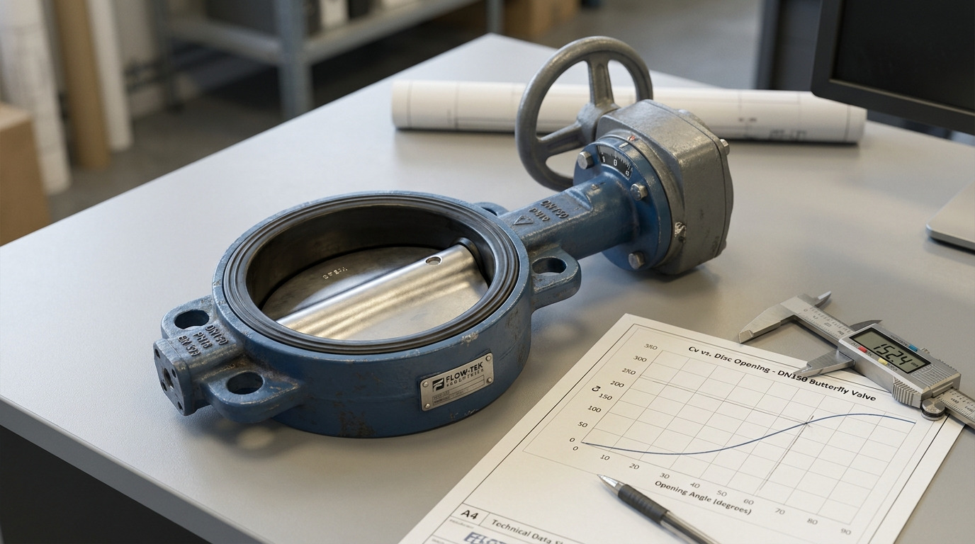
A butterfly valve Cv curve tells you how much flow capacity the valve provides at each disc opening, so you read it by matching your required flow and allowable pressure drop to the valve’s Cv at a realistic operating angle. For engineering selection, the useful question is not only the full-open Cv, but whether the butterfly valve Cv curve gives stable control between the minimum, normal, and maximum flow points.
If you are comparing valve types, start with the basic butterfly valve structure: a quarter-turn disc rotates from closed to open, and the flow path changes quickly as the disc angle changes. In a cooling-water, process-water, HVAC, or utility line, the common problem is simple: the valve may pass enough flow when fully open, but feel too sensitive or unstable when used for throttling. The right way forward is to read the curve together with flow rate, pressure drop, fluid density, pipe layout, and the expected operating angle.
What a Butterfly Valve Cv Curve Shows
A butterfly valve Cv curve shows the relationship between disc opening and flow coefficient, not just whether the valve is open or closed. Cv is the U.S. flow coefficient: the number of U.S. gallons per minute of water at 60 F that can pass through a valve with a 1 psi pressure drop under defined test conditions.
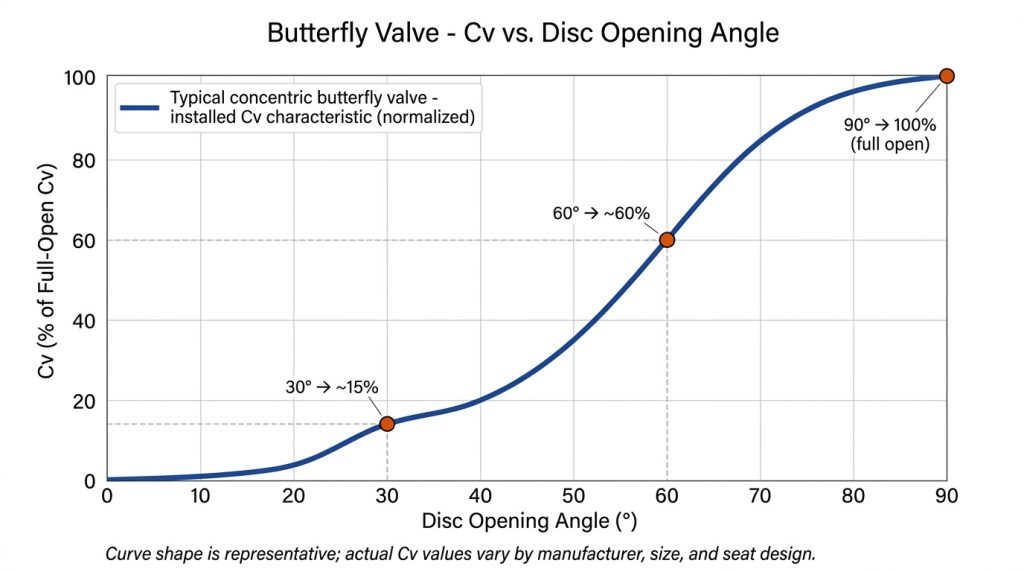
The curve matters because a butterfly valve is not a linear flow device. At small openings, the disc still blocks much of the flow area and creates turbulence. At larger openings, the flow path opens quickly, so the Cv can rise faster than the percent-open number suggests.
How is Cv different from flow rate?
Cv is a capacity rating, while flow rate is what your system actually carries. A valve with Cv 500 does not always pass 500 gpm in service; it passes about 500 gpm of water only when the pressure drop across that valve is 1 psi and the test assumptions apply.
For clean liquids under turbulent, non-choked conditions, the simplified sizing relationship is:
Cv = Q x sqrt(SG / pressure drop)
Here, Q is flow in U.S. gpm, SG is specific gravity, and pressure drop is in psi. For water, SG is usually taken as about 1.0 for preliminary sizing.
What does the curve add beyond full-open Cv?
Full-open Cv tells you maximum capacity, but the curve tells you how the valve behaves before it reaches 90 degrees open. That is important if the valve is used for balancing, modulating service, actuator control, or any duty where you expect intermediate positions.
For example, if a DN150 or NPS 6 butterfly valve has a full-open Cv in the low 1,000s to about 1,600 depending on design, you still need to know whether your normal operating Cv falls near 40 degrees, 60 degrees, or 80 degrees. Those positions can feel very different in actual control.
Why the Cv Curve Is Not Linear
The Cv curve is not linear because disc rotation does not create flow area in a straight-line relationship. A valve that is 50 percent open by angle is not automatically passing 50 percent of its full-open Cv.
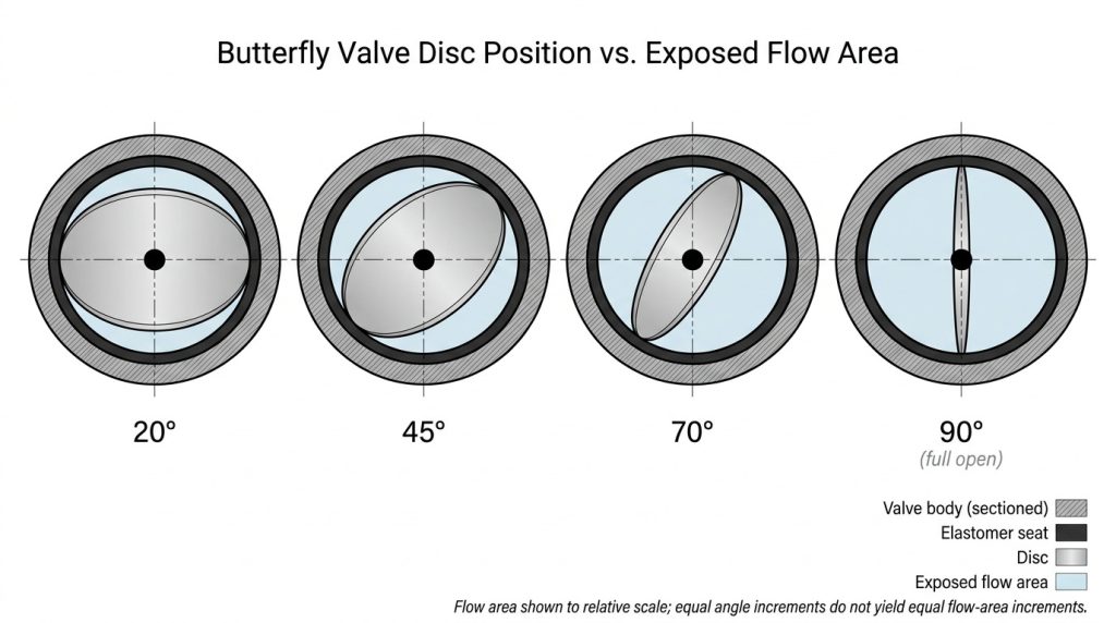
This is why percent-open charts and Cv charts should not be treated as interchangeable. A good butterfly valve flow vs percent open review helps you separate mechanical position from hydraulic capacity, which is the real selection issue.
Why does small disc movement change flow so much?
Small disc movement can change flow sharply when the valve is already in the steeper part of the curve. Near closed position, the disc edge and seat geometry dominate the flow path. Near wide-open position, the remaining restriction is lower, so additional rotation may add less useful control.
This creates a practical risk: if your normal flow sits on a steep curve section, a small actuator movement can cause a large flow change. That can lead to hunting in a control loop, noise, unstable temperature control, or difficulty balancing parallel lines.
Can you interpolate between curve points?
You can use interpolation only as a rough estimate between nearby published points, and only for preliminary checking. Do not assume a straight line from 30 degrees to 90 degrees unless the manufacturer has specifically provided that interpolation method.
The safer approach is to request the actual Cv table or graph for the exact valve size, seat design, disc design, pressure class, and flow direction. This is especially important for larger valves, high-performance designs, and applications where the valve is expected to modulate frequently.
How to Use Cv to Estimate Pressure Drop
Use Cv to estimate pressure drop by rearranging the liquid formula after you know the flow rate and fluid specific gravity. For clean water-like liquids, the simplified relationship is:
pressure drop = SG x (Q / Cv)^2

If your system needs 1,000 gpm of water and the valve Cv at the selected opening is 500, the estimated valve pressure drop is 4 psi. If the same flow passes through a valve position where Cv is 1,000, the estimated drop falls to 1 psi.
How do you calculate Cv for clean liquids?
For a preliminary clean-liquid calculation, divide the required flow by the square root of the available pressure drop, then adjust for specific gravity. If you need 1,000 gpm of water with 4 psi available across the valve, the required Cv is 500.
That number should then be compared with the valve curve at the expected disc opening, not only with the full-open value. A butterfly valve pressure drop chart can help you check whether the selected valve keeps pressure loss within the range your pump or process can tolerate.
When does the simple formula stop being enough?
The simple liquid formula stops being enough when the service involves gas, steam, flashing, cavitation, slurry, non-Newtonian fluids, or high pressure recovery effects. IEC 60534-2-1 and ISA 75.01.01 use more complete sizing methods for control valves, including correction factors for installed conditions and compressible flow.
Butterfly valves are often high-recovery valves, so you should be cautious when pressure drop is high relative to inlet pressure. If the outlet pressure approaches vapor pressure in liquid service, cavitation or flashing can damage the disc, seat, and downstream pipe. In those cases, do not select by Cv alone.
Where the Operating Angle Should Sit
The best operating angle is the part of the curve where a change in disc position produces a manageable change in Cv. For many throttling applications, you want the normal operating point away from the nearly closed region and away from a permanently full-open condition.
A valve that normally runs almost closed may be oversized, noisy, and hard to control. A valve that must run almost fully open may have little reserve capacity when the system demand rises or the strainer begins to foul.
What is a practical throttling range?
A practical throttling range is usually the middle-to-upper part of the opening curve, but the exact range depends on valve design and actuator control. Many butterfly valves become more useful for control after the disc is opened beyond the low-angle region, while very small openings are better treated as shutoff or near-shutoff positions.
For preliminary screening, published clean-water charts often show this broad pattern:
| Disc opening | Typical Cv behavior in published clean-water charts | Practical selection meaning |
|---|---|---|
| 0-20 degrees | Very low Cv, often below about 5% of full-open Cv | Poor region for stable throttling; expect sensitivity and turbulence |
| 30-50 degrees | Low to mid Cv, roughly about 5-35% of full-open Cv depending on design | Useful for some balancing duties, but check curve steepness |
| 60-80 degrees | Main working region, roughly about 40-95% of full-open Cv depending on design | Often better for controllability, but still verify with actual data |
| 90 degrees | Published full-open Cv under defined test conditions | Good for capacity checking, not proof of installed flow control |
The table is a screening guide, not a substitute for the valve data sheet. Final selection should always use the exact valve drawing or Cv table for the ordered size and construction.
How should you read the table below?
Read any Cv table from left to right by disc angle, then compare your calculated required Cv with the closest opening point. If your required Cv falls between two points, note whether the curve is gentle or steep in that area.
If the curve jumps sharply around your normal operating point, the valve may be difficult to modulate. A butterfly valve flow characteristic curve is especially useful when you are diagnosing unstable flow, actuator hunting, or poor balancing after installation.
Key Takeaway: Full-open Cv answers “can the valve pass enough flow?” The curve answers “can the valve pass that flow at a controllable position?”
How Design and Installation Change the Curve
Valve design and installation can change the usable Cv curve enough that nominal size alone is not a reliable selection method. Two butterfly valves with the same DN or NPS size may have different Cv values because of seat type, disc thickness, stem design, body pattern, and pressure class.
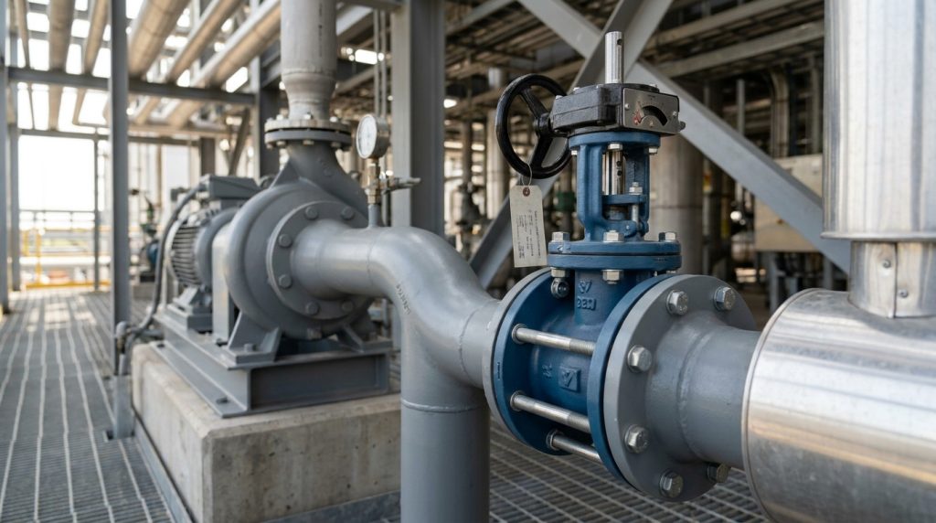
This is why a copied Cv table can be risky. It may be close enough for rough comparison, but not for final sizing, actuator selection, or a project submittal.
How does valve design affect Cv?
A resilient-seat concentric butterfly valve, a double-offset valve, and a high-performance butterfly valve may all have different curves. The disc profile, seat interference, shaft arrangement, and flow direction affect both full-open capacity and intermediate-angle behavior.
API 609, MSS SP-67, and EN 593 help define butterfly valve design, inspection, and construction expectations, but they do not replace the need for a manufacturer-specific Cv curve. Standards help you specify the valve category; the Cv curve helps you judge hydraulic performance.
How do pipe fittings change installed performance?
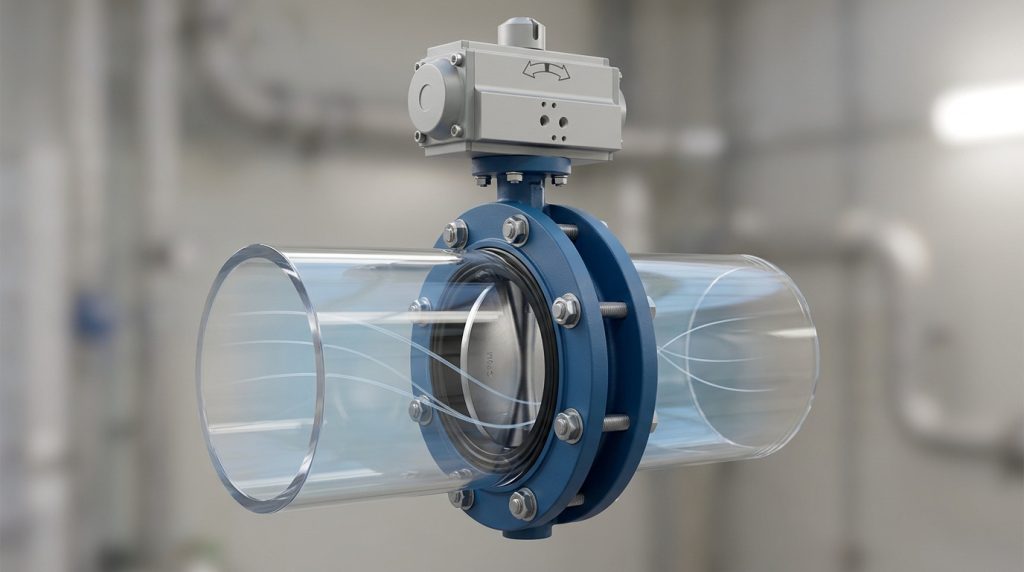
The published curve is usually based on controlled test conditions, while the installed valve sits in a real piping system. Short upstream elbows, reducers, pumps, strainers, tees, and partially open nearby valves can distort the velocity profile entering the disc.
That means the installed curve may not match the inherent curve perfectly. If the valve is close to a pump discharge, elbow, or reducer, allow more caution in pressure-drop estimates and control expectations. For important modulating service, straight-run requirements and actuator positioning accuracy should be reviewed early.
What to Confirm Before You Specify the Valve
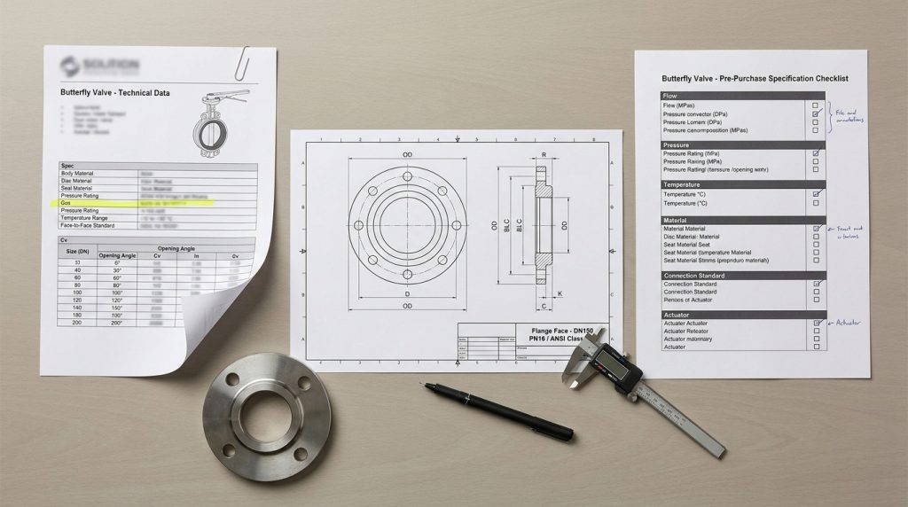
Before you specify the valve, confirm the curve, the test conditions, and the installed pressure drop for your actual operating cases. A good butterfly valve sizing decision usually checks minimum, normal, and maximum flow rather than only one design point.
You should also confirm whether the valve is mainly for isolation, balancing, or control. A butterfly valve can throttle, but it is not always the best precision control valve for severe pressure drop or very fine modulation.
What data should you ask for?
Ask for the exact Cv table or curve for the proposed valve size, pressure class, seat material, disc material, body style, and actuator arrangement. If the project uses metric documentation, ask for Kv as well; the common conversion is Kv = 0.865 x Cv, or Cv = 1.156 x Kv.
For the system side, prepare:
- Fluid type and specific gravity
- Minimum, normal, and maximum flow
- Upstream and downstream pressure at each flow case
- Operating temperature
- Pipe size and connection standard, such as ASME B16.5 Class 150 or EN 1092-1 PN16
- Required shutoff class or leakage expectation
- Manual, pneumatic, or electric actuator requirement
- Any risk of slurry, scaling, cavitation, flashing, or frequent cycling
These details help prevent the common mistake of selecting a valve that looks large enough by size but does not behave well at the required operating point.
How do you compare two valve offers?
Compare two valve offers by checking the Cv at your real operating angle, not by comparing full-open Cv only. If one valve has a higher full-open Cv but places your normal flow at a poor throttling position, it may not be the better choice.
Also compare the assumptions behind the curve. A clean-water Cv table should not be used as proof for steam, air, slurry, or cavitating liquid service. If the valve will be used in control service, review actuator resolution, positioner requirements, seat wear risk, and expected pressure drop together.
Conclusion
A butterfly valve Cv curve helps you connect valve opening, flow capacity, pressure drop, and controllability in one practical view. The strongest selection is not the valve with the biggest full-open Cv; it is the valve whose curve places your real operating points in a stable, usable range.
For final selection, calculate the required Cv, compare it with the exact curve for the proposed valve, and confirm the result against the project drawing or data sheet. If you already have flow, pressure, temperature, material, and connection details, you can share your application details for a focused sizing discussion.
FAQ
Can I size a butterfly valve from full-open Cv only?
No. Full-open Cv is useful for checking maximum capacity, but it does not show whether the valve can control well at normal flow. You need the Cv at the expected disc opening and at minimum, normal, and maximum operating cases.
What’s the best valve opening for control?
The best opening is usually a stable middle-to-upper part of the curve, not the nearly closed region. The exact angle depends on the valve design and system pressure drop, but a normal point that sits too close to closed often means the valve is oversized.
How do I know if the Cv curve is too steep for my system?
The curve is too steep if a small position change causes a large flow change around your normal operating point. In practice, that can show up as unstable flow, actuator hunting, noise, or difficulty maintaining temperature, pressure, or level.
Can I use the same Cv curve for water, steam, and air?
No. A clean-water Cv curve can support preliminary liquid sizing, but steam and air require compressible-flow sizing methods. Use IEC 60534-2-1 or ISA 75.01.01 based calculations, and confirm the valve coefficients and limits for the actual fluid.
What should I send to a supplier for Cv confirmation?
Send the flow range, inlet pressure, outlet pressure, temperature, fluid type, pipe size, connection standard, valve material preference, and actuator requirement. That lets the supplier check the required Cv against the correct valve curve instead of guessing from nominal size.