
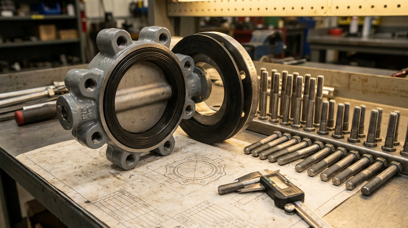
Use a lug butterfly valve bolt chart to match the valve size, flange standard, pressure class, bolt diameter, bolt-hole pattern, and cap-screw length before you order or install the valve. For an ASME Class 150 lug butterfly valve, the flange drilling normally follows ASME B16.5, while the final cap-screw length must still be checked against the valve drawing because tapped lug depth changes by design.
If you are comparing a lug butterfly valve with wafer or flanged designs, the important difference is how each side of the pipeline flange is fastened. A lug valve uses threaded body lugs, so the bolts do not simply pass through both pipe flanges the way they do on many wafer installations.
A common field problem is an 8 inch Class 150 valve that matches the flange face but arrives with cap screws that are too long for the tapped lugs. The valve may look aligned, yet the bolts can bottom out, clash inside through-tapped holes, or fail to develop the right clamping load. The solution is to separate the chart into two checks: standardized flange drilling first, valve-specific bolt length second.
What a Lug Butterfly Valve Bolt Chart Must Confirm
A useful lug butterfly valve bolt chart must confirm both the flange pattern and the lug fastening method, not just the nominal valve size. The chart should help you answer six practical questions before the valve reaches the line.
For ASME projects, ASME B16.5-2025 covers NPS 1/2 through NPS 24 flanges in pressure classes including 150, 300, 400, 600, 900, and 1500, with Class 2500 covered through NPS 12. The standard gives flange dimensions in metric and U.S. customary units, but bolt diameters and bolt-hole diameters are expressed in inch units, which is why metric substitution must be handled carefully.
Check these items in order:
- Valve size, such as NPS 6 or NPS 8
- Flange standard, such as ASME B16.5, EN 1092-1, or JIS B2220
- Pressure class or rating, such as Class 150 or PN16
- Bolt diameter and number of holes per flange face
- Bolt circle diameter, which must match the mating flange
- Lug thread depth and required cap-screw length
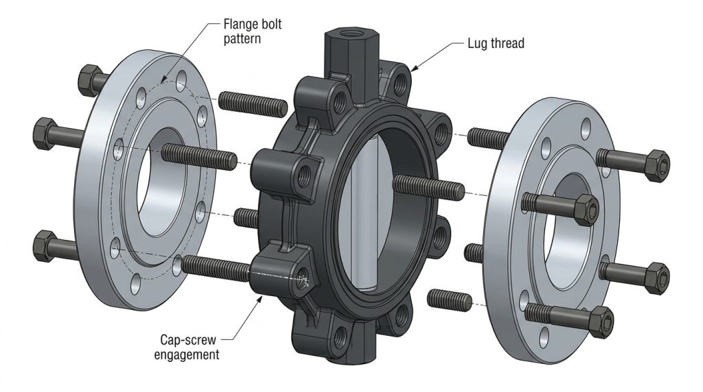
Why lug valves do not use one simple bolt length
Lug valves use separate fasteners from each side of the valve body, so the usual through-bolt length for two flanges is usually the wrong starting point. In a normal two-flange installation, each flange face has its own set of cap screws threaded into the valve body.
This is the main reason a lug chart should show bolt diameter and quantity separately from final length. The flange standard controls the bolt pattern, but the valve body controls how far the cap screw can safely enter the tapped lug.
What should you check before reading the chart?
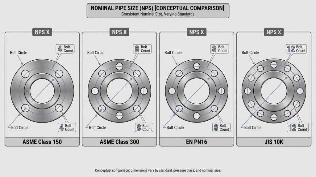
You should confirm the project flange standard before using any bolt size from a chart. A Class 150 ASME pattern, a Class 300 ASME pattern, and an EN PN16 pattern may all appear on industrial butterfly valve projects, but they are not interchangeable.
Also confirm whether the valve is resilient seated, high performance, single offset, double offset, or triple offset. The body thickness, seat retainer side, and lug construction can change the required fastener length even when the flange drilling looks familiar.
ASME Class 150 Lug Butterfly Valve Bolt Chart
The following chart gives common ASME B16.5 Class 150 drilling data for lug butterfly valve sizes often used from NPS 2 to NPS 24. For a deeper Class 150 flange-fit discussion, the Class 150 butterfly valve bolt chart is the closest next step after you confirm the size range.
This table intentionally covers common catalog sizes. NPS 3-1/2 and NPS 22 can appear in flange dimension tables, but they are not always standard catalog lug butterfly valve sizes, so request the valve drawing before ordering those fasteners.
| Valve size | Bolt dia. | Holes per flange face | Cap screws for two flanges | Bolt hole dia. | Bolt circle | Typical short lug cap screw length |
|---|---|---|---|---|---|---|
| NPS 2 | 5/8 in | 4 | 8 | 3/4 in | 4-3/4 in | 1-1/2 in |
| NPS 2-1/2 | 5/8 in | 4 | 8 | 3/4 in | 5-1/2 in | 1-1/2 in |
| NPS 3 | 5/8 in | 4 | 8 | 3/4 in | 6 in | 1-3/4 in |
| NPS 4 | 5/8 in | 8 | 16 | 3/4 in | 7-1/2 in | 1-3/4 in |
| NPS 5 | 3/4 in | 8 | 16 | 7/8 in | 8-1/2 in | 1-3/4 in |
| NPS 6 | 3/4 in | 8 | 16 | 7/8 in | 9-1/2 in | 1-3/4 in |
| NPS 8 | 3/4 in | 8 | 16 | 7/8 in | 11-3/4 in | 2-1/4 in |
| NPS 10 | 7/8 in | 12 | 24 | 1 in | 14-1/4 in | 2-1/4 in |
| NPS 12 | 7/8 in | 12 | 24 | 1 in | 17 in | 2-1/2 in |
| NPS 14 | 1 in | 12 | 24 | 1-1/8 in | 18-3/4 in | 2-3/4 in |
| NPS 16 | 1 in | 16 | 32 | 1-1/8 in | 21-1/4 in | 3-1/4 in |
| NPS 18 | 1-1/8 in | 16 | 32 | 1-1/4 in | 22-3/4 in | 3-1/2 in |
| NPS 20 | 1-1/8 in | 20 | 40 | 1-1/4 in | 25 in | 4 in |
| NPS 24 | 1-1/4 in | 20 | 40 | 1-3/8 in | 29-1/2 in | 4-1/4 in |
The first five data columns are flange-pattern values based on ASME B16.5 Class 150 drilling. The last column is a typical short cap-screw value used in common Class 125/150 tapped lug-body charts; it is not an ASME B16.5 value and must be confirmed against the valve drawing, gasket thickness, washer use, and tapped depth.
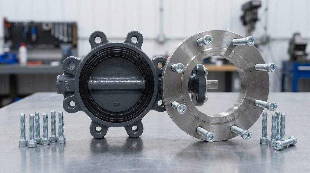
How to Read the Chart Without Ordering Wrong Bolts
You should read the chart from left to right, but you should make the purchase decision from right to left. In other words, the flange standard gives the pattern, while the actual valve construction confirms the final fastener.
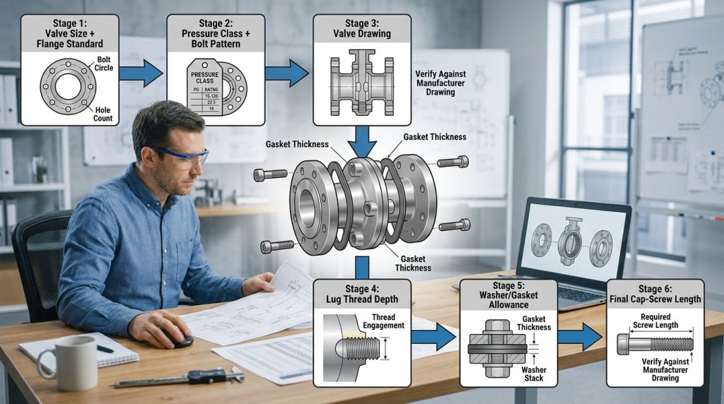
For example, an NPS 8 Class 150 lug valve uses 3/4 inch fasteners, 8 holes per flange face, and 16 cap screws for a normal two-flange installation. If you are checking an 8 inch valve specifically, a size-focused guide such as the 8 butterfly valve bolt size can help you compare wafer, lug, and flanged bolting before you place an order.
Can you use the same chart for Class 300?
No, you should not use a Class 150 chart for Class 300 flanges. ASME B16.5 Class 300 changes the drilling pattern, and the difference is large enough to stop installation.
A simple example shows the risk: NPS 8 Class 150 uses 8 bolts at 3/4 inch diameter, while NPS 8 Class 300 uses 12 bolts at 7/8 inch diameter. The valve may have the same nominal size, but the bolt count and drilling no longer match.
Should you order studs or cap screws?
For most lug butterfly valve installations, cap screws or tap-end studs are used because each side of the flange is fastened independently into the valve body. Full-length studs from a general flange chart are normally intended for through-bolted flange joints and should not be copied directly into a lug valve order.
Use cap screws when the valve drawing calls for cap screws. Use studs only when the drawing, specification, or manufacturer clearly identifies stud length, thread engagement, and whether nuts are required.
Bolt Length and Thread Engagement Need Separate Checks
Bolt length is the most common failure point in lug valve bolting because the standard flange chart does not define the depth of the valve body lug. Two valves can share the same NPS, pressure class, and bolt diameter but still require different cap-screw lengths.
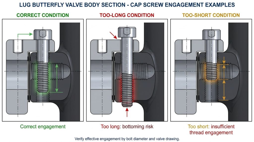
ASME B16.34 requires tapped-hole engagement in flanged valve assemblies to provide full effective thread engagement, excluding chamfer, for a length at least equal to the nominal bolt diameter. In plain terms, a 3/4 inch bolt needs at least 3/4 inch of effective engaged thread unless the applicable project specification or valve design requires more.
What happens if the cap screw is too long?
A cap screw that is too long can bottom in a blind tapped hole or collide with the opposite screw in a through-tapped lug. Either condition can prevent proper gasket compression, damage the lug thread, or crack the lug under tightening load.
This is why lug installation should be treated as a drawing-controlled step, not a guessing exercise. If the job involves end-of-line or one-side removal conditions, review the lug-style installation requirements before assuming the same bolt set works in every orientation.
What happens if the cap screw is too short?
A cap screw that is too short may tighten at first but fail to develop enough engaged thread. That can strip the lug, loosen under vibration, or reduce gasket load after pressure and temperature cycling.
The practical check is simple: confirm bolt diameter, thread pitch, usable thread engagement, and installed length from the valve drawing. Do not count chamfered lead-in threads as full engagement.
When This Bolt Chart Does Not Apply
This chart applies only when the valve and mating flanges are designed around ASME B16.5 Class 150 drilling. It does not apply just because the valve is called a “lug butterfly valve.”
Use a different chart or request a drawing when any of these conditions apply:
- The project specifies ASME Class 300, 600, or higher
- The flange is EN 1092-1 PN10, PN16, PN25, or PN40
- The flange is JIS B2220 10K, 16K, or another regional pattern
- The valve size is NPS 26 or larger and falls under ASME B16.47
- The valve has dual drilling, special drilling, or customer drilling
- The valve is used in dead-end service with manufacturer limits
- The drawing calls for metric bolts instead of inch-series bolts
How do flange standards change the answer?
Flange standards change bolt circle, hole diameter, and bolt count. A DN200 PN16 flange and an NPS 8 Class 150 flange may be close in general pipeline size, but you should not assume their bolt patterns or fasteners are the same.
For global projects, always write the standard and rating in the purchase line. “8 inch lug butterfly valve” is incomplete; “NPS 8 lug butterfly valve, ASME B16.5 Class 150 drilling” is much safer.
Why can dead-end service change the decision?
Dead-end service means one downstream flange may be removed while the valve is still holding pressure from the other side. A lug body can be suitable for this duty only when the valve design, seat direction, pressure rating, and bolting arrangement allow it.
API 609 covers butterfly valve design types including lug and wafer configurations, but it does not turn every lug body into a dead-end valve in every direction. If dead-end isolation matters, specify it clearly along with the required API 609 butterfly valve category, seat direction, and differential pressure.
Material, Torque, and Gasket Checks Around the Chart
The bolt chart confirms physical fit, but it does not fully define bolting performance. Material grade, coating, lubrication, gasket type, flange face, and tightening method all affect whether the joint seals reliably.
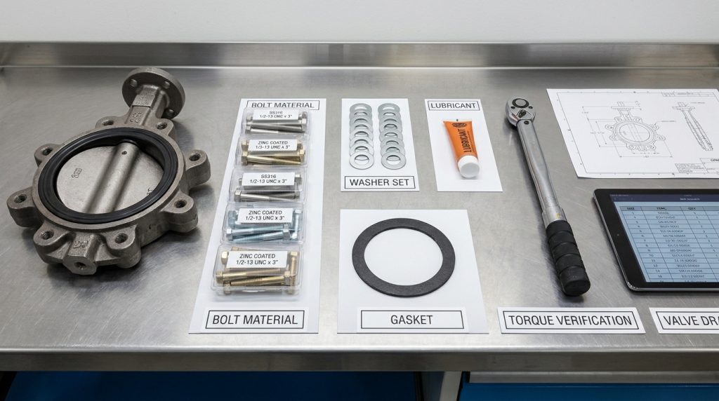
For many carbon steel ASME flange joints, ASTM A193 B7 bolting with ASTM A194 2H heavy hex nuts is commonly specified. Stainless or corrosive services may require ASTM A193 B8 or B8M, while some low-temperature, seawater, chemical, or high-temperature duties need additional material review.
Which thread pitch should you order?
You should order the thread pitch that matches the tapped lugs, not merely the bolt diameter. Common Class 150 charts often show 5/8-11 UNC, 3/4-10 UNC, 7/8-9 UNC, and 1-8 threads, while larger pressure bolting may use 8UN thread series depending on the bolt specification and valve design.
This detail matters because a correct diameter with the wrong thread pitch is still unusable. Always match the drawing callout for the internal lug thread, especially on 1-1/8 inch and larger fasteners.
Can a chart give final torque values?
No, a bolt chart should not be treated as a universal torque chart. ASME PCC-1-2022 treats flange assembly as a controlled process based on gasket stress, bolt stress, lubrication, tightening sequence, and joint condition, not just a single torque number.
Torque also changes with coating and lubricant. A dry bolt, zinc-plated bolt, PTFE-coated bolt, and lubricated B7 bolt can produce different bolt loads at the same wrench reading.
Common Mistakes to Avoid Before Installation
The most reliable way to use a lug butterfly valve bolt chart is to treat it as a fit-check tool, then confirm the remaining details from the project specification and valve drawing. Most problems happen when one of these checks is skipped.
Avoid these mistakes:
- Using a wafer valve through-bolt length for a lug body
- Copying a Class 150 chart into a Class 300 project
- Ordering metric bolts for an ASME inch-drilled valve without confirmation
- Ignoring washer thickness when checking cap-screw length
- Assuming every lug valve is suitable for full-pressure dead-end service
- Counting all tapped-hole depth as effective thread engagement
- Tightening from one side only instead of using a controlled cross pattern
- Reusing damaged fasteners or bolts with unknown coating and grade
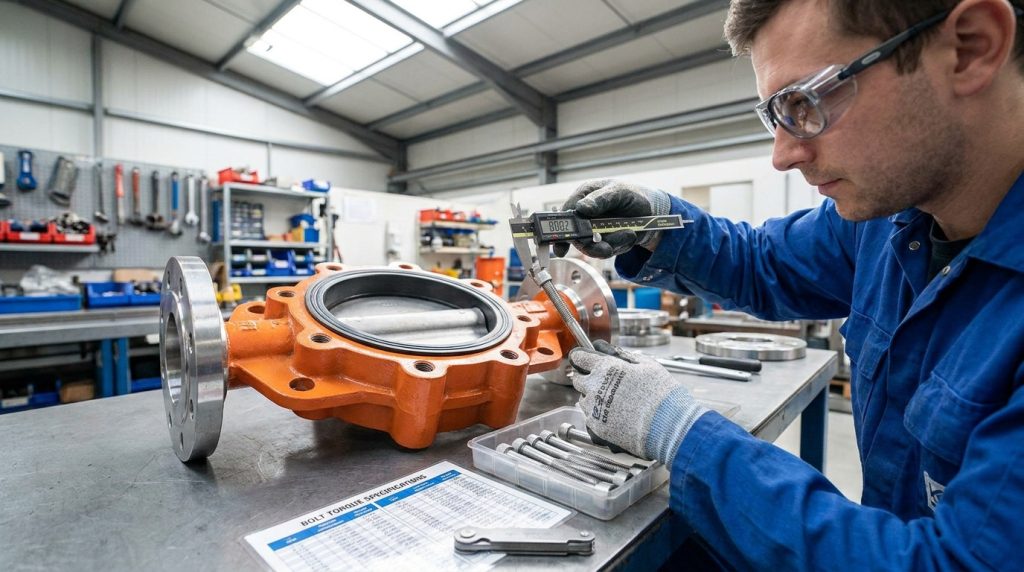
A good purchase description should include valve size, flange standard, pressure class, body type, bolt diameter, thread pitch, cap-screw length, material grade, gasket type, and any dead-end service requirement. That is more useful than a bare request for “butterfly valve bolts.”
Key Takeaway: The chart gives the standardized flange drilling; the valve drawing confirms the safe lug engagement and final fastener length.
Conclusion
A lug butterfly valve bolt chart solves the first part of the fit problem: bolt diameter, number of holes, bolt circle, and flange compatibility. The second part still depends on the lug body, because cap-screw length, thread engagement, retainer side, washer use, and dead-end service limits are valve-specific.
If you are preparing a lug butterfly valve order, gather the valve size, flange standard, pressure class, body material, seat material, gasket type, washer requirement, and dead-end service condition, then contact RUITO to discuss the specification before the fasteners are purchased.
FAQ
Can I use a wafer butterfly valve bolt chart for a lug valve?
No, use it only for the flange pattern, not for bolt length. Wafer valves usually use through-bolts or studs across both flanges, while lug valves use separate fasteners threaded into the valve body.
What’s the best bolt type for a lug butterfly valve?
Cap screws are usually the best starting point when the valve body has tapped lugs. Studs can be correct when the drawing calls for them, but the required stud type and length must be specified.
How do I know if my valve uses Class 150 or Class 300 bolts?
Check the valve drawing, flange standard, and pressure class on the project specification. If the valve is NPS 8, for example, Class 150 and Class 300 use different bolt counts and diameters, so visual size alone is not enough.
Can I replace inch bolts with metric bolts?
Not unless the valve drawing confirms metric tapped holes or dual drilling. ASME B16.5 expresses bolt and bolt-hole diameters in inch units, so a metric “near match” can damage threads or fail inspection.
How do I know if the cap screw length is safe?
Check effective thread engagement and bottoming clearance against the valve drawing. As a practical minimum, tapped flanged valve holes should meet the ASME B16.34 requirement for effective engagement at least equal to the nominal bolt diameter, excluding chamfer.