
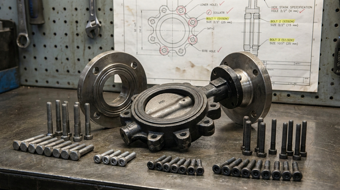
A lugged butterfly valve bolt chart should confirm the flange standard, pressure class, bolt diameter, bolt count, and whether the valve needs cap screws rather than through-bolts. For ASME flanges, the lugged butterfly valve bolt chart is mainly a flange-drilling check; bolt length still has to be confirmed against the valve drawing because lug depth, body thickness, washer use, and gasket practice are not universal.
If you are replacing a valve in an existing line, the risk is usually simple: the valve size looks right, but the bolt pattern or cap screw length does not match the actual flange. This guide explains how to read the chart, where the numbers come from, and when you should move from a general chart to the valve data sheet for industrial butterfly valves.
What a Lugged Butterfly Valve Bolt Chart Must Confirm
A useful chart separates standard flange drilling from valve-specific hardware length. The flange standard tells you bolt circle, hole count, and bolt diameter; the valve design tells you whether those fasteners pass through the body, thread into tapped lugs, or require short cap screws from each side.
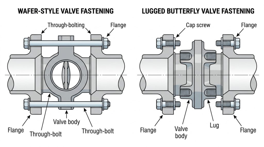
For a lug-style butterfly valve, each pipe flange is normally bolted independently into threaded lugs on the valve body. That is why dead-end service and one-side pipe removal need closer review than a normal between-flanges installation. If the job involves isolating one side of the line, the lug-style butterfly valve installation boundary matters as much as the bolt diameter.
Why does lug style change the bolt count?
Lug style changes the installed hardware count because the bolts usually do not run all the way through both flanges. If an ASME Class 150 NPS 4 flange has 8 bolts per flange, a lug valve installed between two flanges may use 16 cap screws total, 8 from each side.
That does not mean the valve has a different flange pattern. It means the same flange drilling is being used with a different fastening method. This is the first detail to check when a chart lists “quantity,” because some charts list bolts per flange while others list total cap screws per valve.
Lugged Butterfly Valve Bolt Chart by ASME Class
For ASME flanges, start with ASME B16.5-2025 Class 150 or Class 300 drilling, then confirm the lug valve drawing before ordering cap screws. The table below covers common NPS 2–12 sizes because these are frequently checked for lugged butterfly valve replacement and procurement; ASME B16.5 extends beyond this range, and larger or special designs should be checked from the project standard and valve data sheet.
| Valve size | Class 150 bolt circle, in | Class 150 bolt size per flange | Class 300 bolt circle, in | Class 300 bolt size per flange |
|---|---|---|---|---|
| NPS 2 | 4.75 | 4 x 5/8-11 UNC | 5.00 | 8 x 5/8-11 UNC |
| NPS 2-1/2 | 5.50 | 4 x 5/8-11 UNC | 5.88 | 8 x 3/4-10 UNC |
| NPS 3 | 6.00 | 4 x 5/8-11 UNC | 6.62 | 8 x 3/4-10 UNC |
| NPS 4 | 7.50 | 8 x 5/8-11 UNC | 7.88 | 8 x 3/4-10 UNC |
| NPS 5 | 8.50 | 8 x 3/4-10 UNC | 9.25 | 8 x 3/4-10 UNC |
| NPS 6 | 9.50 | 8 x 3/4-10 UNC | 10.62 | 12 x 3/4-10 UNC |
| NPS 8 | 11.75 | 8 x 3/4-10 UNC | 13.00 | 12 x 7/8-9 UNC |
| NPS 10 | 14.25 | 12 x 7/8-9 UNC | 15.25 | 16 x 1-8 UNC |
| NPS 12 | 17.00 | 12 x 7/8-9 UNC | 17.75 | 16 x 1-1/8-7 UNC |
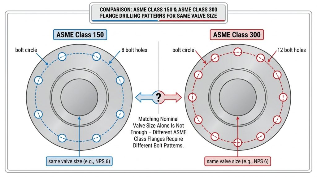
The key pattern is that pressure class can change both the bolt circle and the number of bolts. For example, NPS 6 Class 150 uses 8 bolts per flange, while NPS 6 Class 300 uses 12. If your line is Class 150, a Class 150 butterfly valve bolt chart helps you stay inside the correct drilling pattern before you check valve length.
Class 300 is not simply “stronger Class 150 hardware.” In several sizes, it uses a different bolt circle, larger bolt diameter, or higher bolt count. When your specification calls for Class 300 flanges, check a Class 300 butterfly valve bolt chart instead of upsizing bolts by judgment.
What if the plant uses PN or JIS flanges?
Do not convert ASME bolt sizes into metric and assume the pattern will fit. EN 1092-1 PN16, for example, commonly uses M16 bolts up to DN125, steps to M20 at DN150, and steps to M24 at DN250, but the exact drilling depends on DN, PN rating, flange type, and regional standard.
This matters when a valve is sold globally or when a replacement valve is being fitted into an older line. If the project calls for a PN16 butterfly valve, use the metric flange standard and the valve drawing, not an ASME Class 150 chart with converted units.
Why Bolt Length Is Not One Fixed Chart Value
Bolt diameter and count come from flange drilling, but lug valve bolt length comes from the valve body and installation stack. The length must pass through the pipe flange, any washer or full-face gasket used in that location, and then engage enough internal thread in the lug without bottoming out or hitting the cap screw from the opposite side.
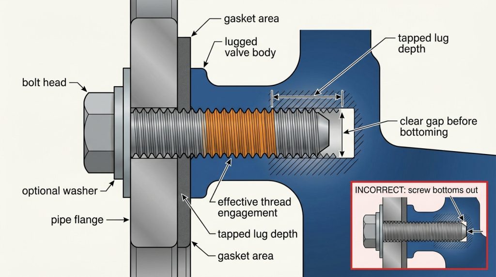
This is where many generic charts become risky. A through-bolt length for a wafer valve can be far too long for a lug body. A cap screw that is too short can strip the lug threads; a cap screw that is too long can give a false torque reading, bottom in a blind hole, or contact the opposite screw in a through-tapped lug.
Can a catalog length be used directly?
A catalog length can be used as a starting point only when the chart matches the valve style, flange class, flange type, gasket assumption, washer assumption, and thread series. The table below shows typical starting lengths for Class 125/150 lug-body butterfly valves with tapped lugs and UNC cap screws. It is useful for screening, not for replacing the manufacturer drawing.
| Valve size | Thread | Typical cap screw length, in | Total cap screws for two flanges | Use boundary |
|---|---|---|---|---|
| NPS 2 | 5/8-11 UNC | 1-1/2 | 8 | Class 125/150 lug body |
| NPS 2-1/2 | 5/8-11 UNC | 1-1/2 | 8 | Class 125/150 lug body |
| NPS 3 | 5/8-11 UNC | 1-3/4 | 8 | Class 125/150 lug body |
| NPS 4 | 5/8-11 UNC | 1-3/4 | 16 | Class 125/150 lug body |
| NPS 5 | 3/4-10 UNC | 1-3/4 | 16 | Class 125/150 lug body |
| NPS 6 | 3/4-10 UNC | 1-3/4 | 16 | Class 125/150 lug body |
| NPS 8 | 3/4-10 UNC | 2-1/4 | 16 | Class 125/150 lug body |
| NPS 10 | 7/8-9 UNC | 2-1/4 | 24 | Class 125/150 lug body |
| NPS 12 | 7/8-9 UNC | 2-1/2 | 24 | Class 125/150 lug body |
The important boundary is the last column. These lengths are typical for a defined installation family, not a universal rule for every lugged butterfly valve. If the valve has thicker lugs, blind tapped holes, liners with special faces, washers under the bolt head, or a different flange standard, the final length must come from the drawing.
How much thread engagement is enough?
The cap screw must have enough effective thread engagement to carry the joint load, but it must not bottom out. As a practical engineering screen, many steel or ductile iron tapped joints are checked around one nominal bolt diameter of effective thread engagement, while softer tapped materials may require more. The project specification and valve drawing still control the final decision.
Do not judge engagement by visible threads at the bolt head. Measure the stack, check the tapped depth, and confirm whether the lug is blind, through-tapped, or tapped from both sides. Opposing screws touching inside the lug is a serious warning sign, not a harmless extra turn.
How Do You Check the Chart Before Ordering?
You check a lugged valve bolt chart by matching the piping flange first, the valve drilling second, and the cap screw length last. This order prevents the most common mistake: using a bolt length table before proving that the pressure class and drilling pattern are correct.
Use this short workflow before releasing a purchase order or field replacement:
- Confirm the valve size by NPS or DN, not by rough outside measurement.
- Confirm the flange standard, such as ASME B16.5, EN 1092-1, JIS, or another project standard.
- Confirm the pressure class or PN rating on the piping specification.
- Match bolt circle, bolt count, and bolt diameter to the valve drawing.
- Check whether the lug holes are through-tapped, blind tapped, or mixed.
- Confirm cap screw length with washer, gasket, and engagement assumptions stated.
- Match material and coating to the service, such as carbon steel, zinc-plated carbon steel, ASTM A193 B7 / A194 2H where specified, or stainless grades for corrosive service.
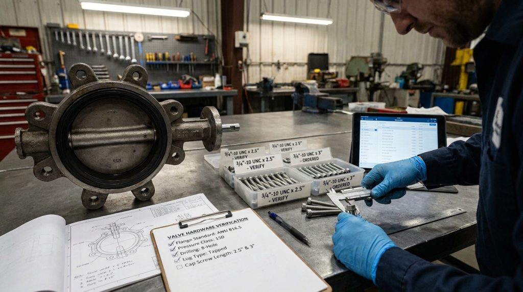
For normal industrial piping, bolt material is not just a purchasing detail. Corrosion, temperature, lubricant, thread condition, and coating affect tightening behavior and long-term removal. If the line specification already names a bolting material, follow that specification instead of substituting hardware because it fits the hole.
Where Bolt Charts Can Mislead Installers
Most bolting mistakes happen when a correct-looking chart is used outside its stated boundary. A chart that is accurate for ASME Class 150 wafer valves can still be wrong for ASME Class 150 lug valves if it lists through-bolt lengths instead of cap screw lengths.
The second common issue is assuming the bolt chart also gives installation torque. Torque depends on bolt grade, lubricant, gasket or seat design, flange facing, coating, and thread condition. A torque number without those assumptions can underload the joint or overload the valve body.
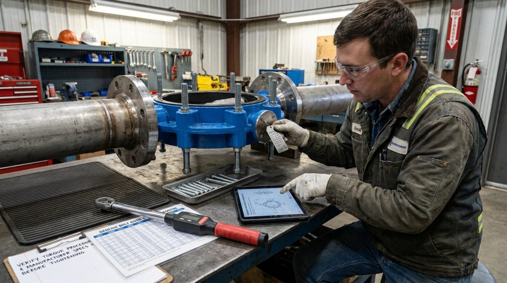
Can torque values be copied from another chart?
No, torque values should not be copied unless the chart uses the same bolt material, thread condition, lubricant, gasket or seat arrangement, and flange condition. Lugged butterfly valves are especially sensitive because the body and liner sit directly between the flanges, and excessive tightening can distort the seat area.
A safer approach is to use the valve manufacturer’s torque guidance when available, tighten in a cross pattern, and increase load gradually. If the chart gives bolt size but not torque conditions, treat it as a dimensional chart, not a complete installation procedure.
What signs show the chart is incomplete?
A chart is incomplete if it does not name the flange standard, pressure class, valve style, thread series, quantity basis, or length assumptions. “Fits 2 inch to 12 inch valves” is not enough for a lugged butterfly valve because the difference between Class 150 and Class 300 can change the bolt count and bolt circle.
Be careful with charts that list metric bolt diameters for ASME flanges without explaining the conversion. ASME B16.5 flange drilling uses inch bolt diameters, and the tapped lugs of an ASME-pattern valve are normally designed around the matching inch thread series.
When Should You Escalate Beyond the Chart?
Escalate beyond the chart when the installation condition changes the load path, pressure boundary, or service risk. A general bolt chart is helpful for screening, but it cannot confirm every detail of dead-end service, high-temperature duty, corrosive media, vibration, or nonstandard flange combinations.
You should request the valve drawing or technical confirmation when any of these conditions apply:
- One downstream flange may be removed during maintenance.
- The valve is used at elevated temperature or in thermal cycling.
- The line has strong vibration, pulsation, or frequent operation.
- The flanges are old, mixed-standard, or not clearly identified.
- The valve is Class 600, larger than the chart range, or custom drilled.
- The service requires a named bolting grade, coating, or traceability.
- The installation uses gaskets, spacers, washers, or special flange faces not covered by the chart.
API 609 covers butterfly valve categories and requirements for lug, wafer, double-flanged, and butt-welding end designs, but it does not make every lug valve bolt length interchangeable. The final fit still comes from the actual flange standard, the valve body drawing, and the project bolting specification.
Conclusion
A lugged butterfly valve bolt chart helps you confirm bolt diameter, bolt count, flange class, and the difference between through-bolting and cap screws. The strongest use of the chart is not guessing a length; it is catching mismatches before the valve reaches site.
If you need to confirm a lugged butterfly valve for an ASME, EN, or mixed-flange project, send the valve size, flange standard, pressure class, media, temperature, material requirements, and any available drawing through contact us so the specification can be reviewed before hardware is ordered.
FAQ
Can I use a wafer butterfly valve bolt chart for a lug valve?
No, not for bolt length. A wafer chart may help you understand the flange drilling, but wafer valves usually use through-bolts or studs while lug valves often use short cap screws into tapped lugs. Use a lug-specific chart or the valve drawing for cap screw length.
What’s the best bolt material for a lugged butterfly valve?
The best material is the one required by the project specification and service condition. Carbon steel hardware may be acceptable in general water service, while corrosive, high-temperature, or pressure piping specifications may call for materials such as ASTM A193 B7, B8, B8M, or other defined grades.
How do I know if my lug valve uses Class 150 or Class 300 bolts?
Check the piping flange class and the valve drawing, not only the valve size. Class 150 and Class 300 can use different bolt circles, bolt counts, and bolt diameters for the same NPS size, so the pressure class is essential.
Can I reuse old bolts when replacing a lugged butterfly valve?
Only if the old bolts match the required diameter, thread, grade, length, coating, and condition. If threads are worn, corroded, stretched, or the old length does not match the new lug depth, replacement hardware is the safer choice.
What’s the best way to avoid cap screws touching inside the lug?
Confirm the tapped depth and maximum permitted cap screw length from the valve drawing. A screw should engage enough thread to hold the joint, but it should not bottom out or contact the screw entering from the opposite side.