

A butterfly valve p&id symbol shows a quarter-turn valve, its operator, normal position, and control relationships within a process line. You may face a drawing review where a small symbol must guide purchasing, wiring, installation, and safe isolation. If its disc mark, actuator, or tag gets misread, your team could order unsuitable hardware or plan an unsafe shutdown. This guide gives you a practical reading method grounded in current P&ID practice and real valve construction.
What Does a Butterfly Valve P&ID Symbol Show?
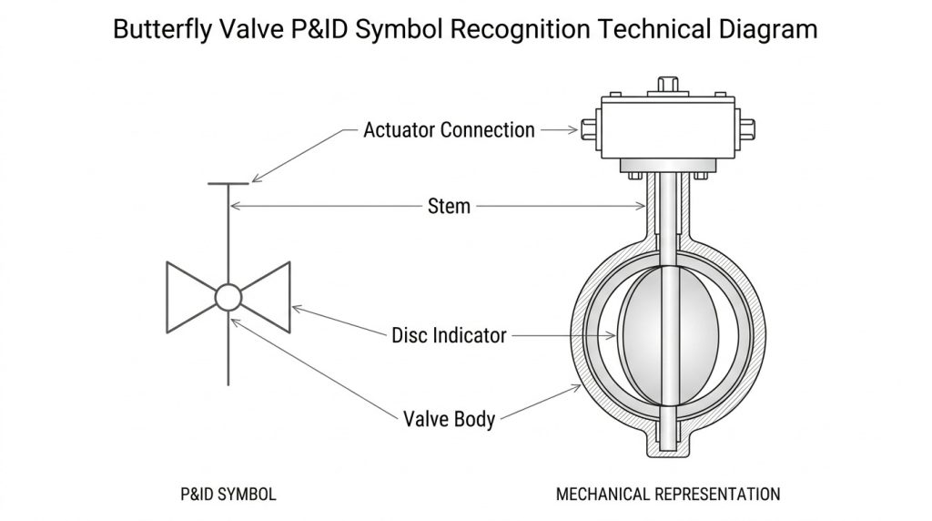
A butterfly valve p&id symbol shows a rotary disc valve installed in a pipeline and may also show its operating method. Its base graphic varies among company libraries, so you might see a bow-tie valve body with a disc mark or a circle crossed by a line. Always treat the project legend as the controlling visual dictionary.
Which visual features identify it?
Start with its mechanical idea: a butterfly valve uses a circular disc that turns about 90 degrees. The drawing compresses that construction into a few recognizable marks:
- A valve-body mark placed directly on the pipe
- A line, bar, or central feature representing the disc
- A stem leading toward a lever, gearbox, or actuator
- A nearby tag tied to a valve schedule
What should you confirm before naming it?
Check body shape, disc indicator, actuator mark, and tag before making a selection. Similar-looking symbols can represent different valve families under another drafting convention.
| Check | What it tells you | Where to verify |
|---|---|---|
| Body graphic | Valve family | Drawing legend |
| Stem or disc mark | Rotary mechanism | Symbol standard |
| Tag | Unique asset | Valve schedule |
This combination gives stronger evidence than shape alone.
Key Takeaway: You can identify a butterfly valve confidently when symbol geometry, tag data, and project legend agree.
How Does It Compare with Other Valve Symbols?
A butterfly valve p&id symbol differs from globe, ball, gate, and check valve graphics through its rotary-disc cue and attached operator details. A globe valve normally signals linear throttling, while a check valve shows one-way action. Exact shapes still depend on the drawing convention adopted for your project.
Which differences matter during a drawing review?
Here is the useful shortcut: compare function before comparing artwork. You can narrow the choice by asking what movement and flow duty each graphic communicates:
- Butterfly valve: quarter-turn disc for isolation or control
- Globe valve: linear plug for regulated throttling
- Ball valve: quarter-turn ball for tight shutoff
- Gate valve: linear gate for low-loss isolation
- Check valve: automatic prevention of reverse flow
Where do readers commonly get confused?
Confusion occurs when a simplified library omits internal detail or when scanned drawings lose thin lines. Use adjacent tags, operators, and line notes as supporting evidence.
| Valve type | Motion | Main P&ID clue |
|---|---|---|
| Butterfly | Rotary | Disc or stem cue |
| Globe | Linear | Plug or body cue |
| Check | Automatic | Directional closure cue |
This comparison shows why one internal mark can change procurement meaning.
Key Takeaway: You can separate similar symbols faster by matching graphic cues with valve motion and process duty.
Which Manual and Actuated Symbol Types Appear?
A butterfly valve p&id symbol can represent manual, pneumatic, electric, or hydraulic operation through an operator graphic above its stem. Manual versions may carry a lever, handwheel, or gearbox mark. Automated versions add an actuator and may show instrument-air, electrical, or hydraulic connections.
How can you recognize each operating method?
Look one step above the valve body: that area normally tells you who or what moves the disc. Common additions include:
- Lever or T-handle for local manual operation
- Handwheel and gearbox for higher torque
- Pneumatic actuator with an air signal
- Electric motor actuator with power or control notation
- Hydraulic actuator for high-force service
What does each type imply for your project?
Operator choice affects utilities, controls, access space, cycle time, and fail action. A symbol should lead you toward those questions before a purchase request leaves engineering.
| Operator | Supporting need | Typical drawing cue |
|---|---|---|
| Manual | Local access | Lever or handwheel |
| Pneumatic | Clean instrument air | Air signal and actuator |
| Electric | Power and controls | Motor operator |
The table turns a small graphic into a practical scope check.
Key Takeaway: You can use operator marks to identify utility, wiring, access, and safety requirements early.
How Do Connection Styles Affect the Symbol?
A butterfly valve p&id symbol may include flange or end-connection marks, though many P&IDs leave wafer, lug, and flanged details in a valve schedule. Wafer bodies sit between flanges, lug bodies use threaded lugs, and double-flanged bodies carry integral flanges. Never assume body style from a generic valve icon.
Which connection clues may appear?
The detail sits at each pipe interface: short parallel lines can indicate flanges, while other end marks may indicate welded or threaded joints. Your review should cover:
- Wafer body sandwiched between mating flanges
- Lug body bolted independently on either side
- Double-flanged body with integral flange faces
- Welded ends for selected severe services
For dead-end work, review lug-style butterfly valve installation limits against manufacturer ratings.
Why does the distinction affect maintenance?
Body style changes bolt arrangement, alignment practice, downstream pipe removal, and allowable dead-end pressure. A P&ID alone may not contain enough construction detail.
| Body style | Mounting method | Maintenance concern |
|---|---|---|
| Wafer | Through-bolts | Both flanges restrain body |
| Lug | Separate flange bolts | Dead-end rating needs review |
| Flanged | Integral flanges | More space and weight |
This view connects drafting detail with field access.
Key Takeaway: You can avoid flange and bolt errors by checking connection marks against schedules and approved valve data.
How Can You Read Open, Closed, and Fail Positions?
A butterfly valve p&id symbol communicates normal or failure position only when the project convention adds clear position notation. Labels such as NO, NC, FO, FC, or FL usually carry more authority than a guessed disc angle. Read them beside control logic and cause-and-effect documents.
What do common position codes mean?
This is where operating context matters: “normal” describes an agreed process condition, while “fail” describes behavior after loss of motive power or signal. Typical codes include:
- NO: normally open
- NC: normally closed
- FO: fail open
- FC: fail closed
- FL: fail locked or fail in last position
Can symbol fill or orientation prove valve status?
No, not without a project legend that defines those conventions. Disc orientation and symbol fill may carry meaning in one library but remain purely graphic elsewhere.
| Code | Intended state | Review question |
|---|---|---|
| NO or NC | Normal operation | Which operating case defines normal? |
| FO or FC | Loss of power | Which energy source has failed? |
| FL | Holds position | Is stored energy available? |
This distinction keeps normal position separate from failure response.
Key Takeaway: You can read valve state safely when explicit codes, control narratives, and actuator design tell the same story.
Which Tags and Annotations Prevent Ambiguity?
A butterfly valve p&id symbol becomes traceable when its tag matches valve schedules, data sheets, control documents, and maintenance records. A tag may identify valve function or loop relationship rather than spell out body type. Your company tagging procedure remains the deciding reference.
What information belongs beside the graphic?
A clean tag does more than name equipment: it links drawings with engineering records. Depending on project practice, nearby data can include:
- Unique valve or loop identifier
- Normal and fail position
- Actuator or solenoid reference
- Line number and service
- Control signal or interlock relationship
How should tags connect with other deliverables?
Keep one identifier across P&IDs, valve lists, instrument indexes, I/O lists, data sheets, and work orders. Revision control should also capture field replacements.
| Record | Tag-linked information | Main user |
|---|---|---|
| Valve schedule | Size, class, materials | Piping |
| Data sheet | Duty and actuator details | Procurement |
| I/O list | Signal assignment | Controls |
This linkage reduces manual interpretation between disciplines.
Key Takeaway: You can prevent handoff errors when every document uses one controlled tag for the same physical valve.
Where Are Butterfly Valve Symbols Used?
A butterfly valve p&id symbol appears wherever compact quarter-turn isolation or throttling suits process duty, including water, HVAC, air, utility, chemical, and selected slurry systems. Its presence does not prove material suitability. Media, pressure, temperature, velocity, corrosion, abrasion, and shutoff class still drive selection.
Which services commonly use butterfly valves?
Their compact geometry earns its place: large line sizes often favor butterfly valves because weight and face-to-face length stay manageable. Common services include:
- Cooling-water and treatment lines
- HVAC chilled-water and condenser loops
- Fire-water distribution
- Compressed-air and low-pressure gas systems
- Compatible chemical or process utilities
Where should you apply extra caution?
Review flashing, cavitation, erosive slurry, high temperature, hazardous leakage, vacuum, and frequent throttling with a valve specialist. Disc and seat design can change suitability sharply.
| Service | Selection focus | Drawing follow-up |
|---|---|---|
| Water or HVAC | Corrosion and shutoff | Size and body style |
| Chemical | Material compatibility | Seat and disc data |
| Slurry | Abrasion and velocity | Disc clearance |
This quick screen points each symbol toward service-specific questions.
Key Takeaway: You can treat a P&ID symbol as a starting point, then select construction from actual process conditions.
Which Standards Should Guide Your P&ID?
A butterfly valve p&id symbol should follow the symbol set named in project specifications and drawing legends. ISO 10628-2 covers graphical symbols for chemical and petrochemical process diagrams, while ANSI/ISA-5.1 addresses instrumentation and control symbols and identification. Company standards may add permitted project-specific variants.
How should you apply standards without mixing conventions?
Consistency carries more value than decoration: choose an approved library, record its basis, and use it throughout every sheet. Your drafting controls should cover:
- One approved symbol library
- A lead-sheet legend
- Defined tag syntax
- Uniform line weights and signal types
- Controlled revision and approval records
What should a drawing legend explain?
Define every custom valve body, actuator, signal, failure code, and status convention that could change interpretation. Reference standards should be named with their adopted editions.
| Control item | Required decision | Project record |
|---|---|---|
| Symbol set | Approved convention | CAD library |
| Identification | Tag structure | Tagging procedure |
| Custom variant | Meaning and limits | Lead-sheet legend |
This framework keeps design teams and site personnel aligned.
Key Takeaway: You can support consistent interpretation through one approved library, a precise legend, and controlled revisions.
What Drafting Mistakes Cause Costly Errors?
A butterfly valve p&id symbol causes costly errors when its type, operator, fail action, or tag conflicts with another project record. Typical failures arise from copied symbols, stale revisions, missing actuator signals, and undocumented custom graphics. These gaps often surface during purchasing or commissioning.
Which checks catch mistakes early?
A short review can save a field change: compare each critical valve with process duty and connected controls. Focus on:
- Duplicate or missing tags
- Wrong valve family or body style
- Unclear normal and fail positions
- Missing actuator utility or signal
- Mismatched line class and valve rating
- P&ID data that differs from schedules
Who should review each symbol?
Piping, process, controls, operations, maintenance, and safety roles should review relevant attributes at agreed project gates. A single-discipline check rarely catches every interface.
| Error | Likely impact | Review owner |
|---|---|---|
| Wrong body type | Fit-up or service issue | Piping |
| Wrong fail action | Process hazard | Process and controls |
| Stale tag | Commissioning delay | Document control |
This assignment makes review responsibility visible.
Key Takeaway: You can reduce rework when each discipline checks defined symbol attributes before drawings reach construction.
How Do You Verify a Symbol Against Field Hardware?
A butterfly valve p&id symbol is verified through a structured walkdown that matches its tag, body, actuator, position, and connections with installed equipment. Record discrepancies rather than altering a master drawing informally. Approved redlines should flow through change control into an as-built revision.
What should you inspect at the valve?
Bring the drawing close to the asset: a field check should compare visible evidence with controlled records. Inspect:
- Permanent tag and line number
- Wafer, lug, or flanged body
- Manual, pneumatic, electric, or hydraulic operator
- Disc-position indicator
- Solenoid, limit switches, and positioner
- Accessible flow arrow or nameplate data
How should discrepancies be closed?
Classify each mismatch, assess operating risk, confirm design intent, and assign an owner. Update affected schedules, data sheets, control records, and drawings under one change package.
| Field finding | Immediate action | Final record |
|---|---|---|
| Tag mismatch | Verify asset identity | Corrected index |
| Operator mismatch | Check control function | Revised data sheet |
| Body mismatch | Review service rating | Approved as-built P&ID |
This closure path prevents a redline from becoming another isolated record.
Key Takeaway: You can keep P&IDs trustworthy through disciplined walkdowns, risk review, and controlled as-built updates.
Ready to Specify the Right Butterfly Valve?
You can now identify a butterfly valve graphic, compare nearby valve types, read actuation and position cues, interpret tags, check standards, and verify installed hardware. For support matching body style, materials, actuator, and service data with your drawing, contact us today and share your process conditions.
RuitoFlow believes accurate documentation and dependable valve engineering should work as one system. We help your team turn P&ID intent into practical valve specifications that support safer installation, clearer maintenance, and reliable flow control.
Frequently Asked Questions
Can I use one butterfly valve symbol for every body style?
Yes, if your project convention uses a generic symbol. Put wafer, lug, or flanged construction in the valve schedule and data sheet, then define any symbol variants in the legend.
What’s the best way to show a fail-safe position?
Use an explicit fail code such as FO, FC, or FL beside the actuator or tag. Confirm its meaning in the legend and align it with control narratives.
How do I know if a butterfly valve is normally open?
Look for an NO label or another status convention defined by the project legend. Do not rely on fill color or disc angle unless that convention appears in controlled drawing notes.
Can I identify actuator power from the P&ID?
Often, yes. Actuator graphics, signal lines, solenoid tags, motor references, or hydraulic connections can identify power type, though supporting data sheets provide fuller detail.
What’s the best check before ordering a valve?
Cross-check tag, size, pressure class, body style, materials, process conditions, actuator, failure position, and required accessories. Resolve every conflict between P&ID, schedule, and data sheet before release.