
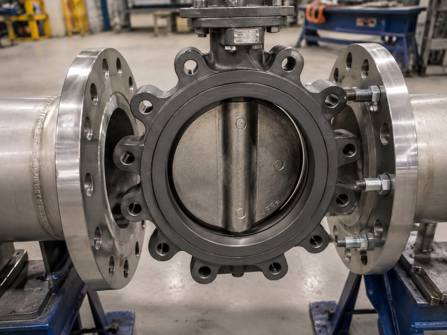
A lugged butterfly valve bolt chart should confirm the flange drilling first, then leave final cap-screw length and thread engagement to the valve drawing. That distinction prevents a common site problem: the diameter and hole pattern match, but the screws are too short to develop safe engagement or too long to clamp the flange before they bottom in the lugs.
Use the chart below to screen an ASME Class 150 installation, not to release hardware from the chart alone. The exact body series, tapped-hole arrangement, flange thickness, washer stack, and gasket or seat-face practice still control final fit. If you are still defining the valve configuration, start with the available industrial butterfly valve options before fixing the bolting package.
Read the Chart as Two Separate Decisions
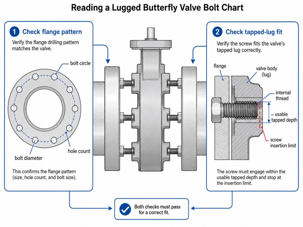
The safe reading method has two gates: standard flange compatibility and valve-specific fastener fit. Passing one gate does not prove the other.
Gate 1 — flange pattern: Match NPS, flange standard, pressure class, bolt circle, hole count, and nominal bolt diameter. ASME B16.5-2025 covers NPS 1/2 through NPS 24 flanges and includes Class 150 and 300 dimensional requirements. Its public scope also makes clear that bolt and bolt-hole diameters are expressed in inch units, even though the standard supplies both metric and U.S. customary dimensions.
Gate 2 — tapped-lug fit: Match the internal thread, usable tapped depth, blind or through-hole construction, required effective engagement, maximum insertion, and under-head screw length. These dimensions belong to the valve design and installation stack, not to the flange standard alone.
A purchase order is ready only when both gates pass against controlled documents.
ASME Class 150 Lugged Butterfly Valve Bolt Chart
This chart provides common Class 150 screening data for NPS 2 through NPS 24. “Holes per flange” describes one pipe flange; “total cap screws” assumes a normal valve installed between two flanges with a separate screw entering each lug from each side.
| Valve size | Common tapped thread* | Holes per flange | Total cap screws for two flanges | Bolt circle, in. |
|---|---|---|---|---|
| NPS 2 | 5/8-11 UNC | 4 | 8 | 4.75 |
| NPS 2-1/2 | 5/8-11 UNC | 4 | 8 | 5.50 |
| NPS 3 | 5/8-11 UNC | 4 | 8 | 6.00 |
| NPS 4 | 5/8-11 UNC | 8 | 16 | 7.50 |
| NPS 5 | 3/4-10 UNC | 8 | 16 | 8.50 |
| NPS 6 | 3/4-10 UNC | 8 | 16 | 9.50 |
| NPS 8 | 3/4-10 UNC | 8 | 16 | 11.75 |
| NPS 10 | 7/8-9 UNC | 12 | 24 | 14.25 |
| NPS 12 | 7/8-9 UNC | 12 | 24 | 17.00 |
| NPS 14 | 1-8 UNC | 12 | 24 | 18.75 |
| NPS 16 | 1-8 UNC | 16 | 32 | 21.25 |
| NPS 18 | 1-1/8 in.; verify thread series | 16 | 32 | 22.75 |
| NPS 20 | 1-1/8 in.; verify thread series | 20 | 40 | 25.00 |
| NPS 24 | 1-1/4 in.; verify thread series | 20 | 40 | 29.50 |
*The thread column is a common tapped-lug starting point, not a substitute for the thread callout on the approved valve drawing. Large or special bodies may use blind holes, mixed blind and through holes, or a different thread series.
The most important chart-reading point is the quantity basis. An NPS 4 Class 150 flange has eight holes, but a two-flange lug installation normally needs 16 short cap screws. If a vendor’s Qty column does not say “per flange” or “per valve,” stop and clarify it before ordering.
Class 150 and Class 300 Are Not Interchangeable
Pressure class can change the bolt circle, diameter, and hole count for the same nominal size. Do not keep a Class 150 valve pattern and merely select a stronger bolt for a Class 300 line.
| Valve size | Class 150 pattern per flange | Class 300 pattern per flange |
|---|---|---|
| NPS 2 | 4 × 5/8-11 on 4.75-in. circle | 8 × 5/8-11 on 5.00-in. circle |
| NPS 6 | 8 × 3/4-10 on 9.50-in. circle | 12 × 3/4-10 on 10.62-in. circle |
| NPS 8 | 8 × 3/4-10 on 11.75-in. circle | 12 × 7/8-9 on 13.00-in. circle |
| NPS 12 | 12 × 7/8-9 on 17.00-in. circle | 16 × 1-1/8-7 on 17.75-in. circle |
These examples show why the pressure class must appear in the RFQ and drawing title. For the complete higher-class workflow, use the dedicated ASME Class 300 butterfly valve bolt chart rather than extrapolating from Class 150.
Calculate Cap-Screw Length From the Actual Stack
Final cap-screw length is the sum of the parts outside the lug plus the permitted engagement inside it. Use this screening relationship before checking a standard available screw length:
Trial under-head length = washer stack + flange thickness + permitted face or gasket allowance + required effective thread engagement
The “permitted” wording matters. Some resilient-seat designs seal directly at the valve seat face and prohibit an added flange gasket; other valve and flange combinations require a gasket. A raised face, spacer, unusually thick coating, or hardened washer also changes the stack. Use the valve IOM and drawing instead of adding components by habit.
Establish the maximum safe insertion
The selected length must also stay below the maximum insertion allowed by the lug. For a blind hole, reserve the drawing-specified bottom clearance. For a through-tapped lug, check whether the opposite-side screw can enter the same internal space. Neck and shaft locations may have shallower blind holes than the other lugs.
Run a dry fit before applying torque
Clean the threads, confirm the screw can be turned by hand, and assemble the actual flange, permitted gasket or seat interface, and washers. The head must seat on the flange or washer before the screw reaches the bottom or contacts the opposing fastener. If it stops early, do not use wrench torque to force it farther; recheck the length and tapped-hole map.
Verify Engagement Without Guessing From the Bolt Head
Effective engagement is the fully formed internal and external thread length carrying load. Visible thread at the head does not tell you how much usable thread is engaged inside the body.
Use the approved drawing to record four values for each lug type: internal thread designation, usable tapped depth, required minimum engagement, and maximum screw insertion. Then compare those values with the calculated under-head length and the dry-fit result. If the valve mixes through holes with blind holes, release separate fastener callouts rather than one “typical” length for every position.
Reject the fit when any of these signs appears:
- The head remains clear of the flange when the screw stops.
- Opposing screws touch inside a through-tapped lug.
- The available engagement is below the drawing minimum.
- The screw starts only with a wrench, indicating a pitch, coating, or thread-condition problem.
- One position needs a different length but the bill of materials lists a single part number.
This position-by-position check closes an execution gap that a generic chart cannot resolve.
Keep Torque Separate From the Dimensional Chart
A bolt diameter does not produce one universal torque value. Fastener material and grade, coating, lubricant, thread condition, washer type, gasket or seat design, flange condition, and target bolt load all change the torque-to-preload relationship.
ASME PCC-1-2022 treats pressure-boundary bolted-flange assembly as a controlled procedure selected for the service and joint. For a lugged butterfly valve, use the approved valve IOM and project bolting procedure, then tighten in the specified cross pattern and staged passes. Do not copy a torque number from a chart that fails to state its bolt grade, lubrication, gasket or seat arrangement, and joint assumptions.
A suspicious torque response is also a fit warning. If the wrench reaches the target while the flange is not seated uniformly, stop and check for screw bottoming, misalignment, an unapproved gasket, or seat interference.
Know When This Chart Stops Applying
This Class 150 chart stops applying when the standard, pressure class, size range, or valve construction changes. Use a different controlled chart and drawing for EN 1092 PN flanges, JIS flanges, ASME Class 300 or higher, NPS 26 and larger ASME B16.47 flanges, dual drilling, customer drilling, and metric tapped lugs.
Dead-end service also requires a separate rating decision. The current API standards plan lists API 609, 10th Edition, for double-flanged, lug, wafer, and butt-welding-end butterfly valves, but the word “lug” alone does not establish dead-end pressure, permitted flow direction, seat orientation, or the bolting required with one flange removed. State those conditions explicitly and confirm the applicable API 609 valve specification details before approving one-sided service.
Release a Complete Bolting Package
A complete release identifies the interface, the hardware, and the evidence used to approve them. Put the following information on the RFQ, purchase order, or installation work pack:
- Valve tag, NPS or DN, body series, and revision-controlled drawing
- Flange standard, pressure class or PN rating, facing, and measured thickness
- Bolt circle, holes per flange, and total fastener quantity basis
- Tapped-thread designation and a map of blind, through, and special positions
- Cap-screw type, under-head length, material grade, coating, and traceability requirement
- Washer type and thickness
- Gasket or no-gasket requirement from the valve IOM
- Minimum effective engagement and maximum insertion by lug position
- Approved torque procedure, lubricant condition, and tightening sequence
- Dead-end pressure, direction, and one-flange-removal requirement, if applicable
The drawing approval should state which values come from the flange standard and which come from the valve body. That single boundary makes future replacement work much easier to audit.
Use the Chart to Screen, the Drawing to Release
The chart can confirm Class 150 bolt diameter, hole count, total two-flange quantity, and bolt circle. It cannot by itself confirm cap-screw length, tapped depth, bottom clearance, torque, gasket practice, or dead-end rating.
Before ordering, pass the flange-pattern gate and the tapped-lug gate, then document the assumptions on the approved drawing. For a project-specific review, send the valve size, flange standard and class, flange thickness, gasket and washer details, service conditions, and available drawings when you contact RUITO.
FAQ
Can I reuse the old cap screws when replacing a lug valve?
Only after every relevant attribute is reverified. Confirm diameter, thread, under-head length, grade, coating, condition, engagement, and bottom clearance against the new valve drawing; replace any screw with corrosion, damaged threads, uncertain traceability, or a mismatched length.
Can stainless fasteners replace carbon steel bolts of the same size?
Not by size alone. Stainless and carbon steel fasteners can have different strength, galling behavior, lubrication requirements, and approved torque procedures, so the project bolting specification must authorize the material substitution.
Does a resilient-seated lug valve need a separate flange gasket?
It depends on the valve design. Many resilient-seat valves use the seat face as the flange seal and do not permit an additional gasket, while other designs require one; follow the valve IOM because an unapproved gasket can change both sealing behavior and cap-screw length.