

A butterfly valve is fully open when its disc is parallel to the flow path and fully closed when the disc is perpendicular across the bore. The basic geometry is simple, but the butterfly valve open and closed position can be misidentified when a handle has been reinstalled, a gearbox pointer is out of adjustment, or an actuator signal does not match the valve’s actual travel.
That is why a quick visual check is useful but not always sufficient. Across different industrial butterfly valve configurations, you should read the local operator first, then confirm its indication against a second independent signal whenever position affects operation, isolation, or an interlock.
What Open and Closed Mean Inside the Valve
In the open position, the disc turns so its face is generally parallel to the pipe axis; in the closed position, the disc turns across the bore and contacts the seat. A butterfly valve is a quarter-turn valve, so the disc normally travels about 90 degrees between these two end positions.
At full open, the disc’s thin edge faces the flow, but the disc and stem remain inside the bore. The valve therefore has a mostly clear flow path, not an empty full bore. At full closed, the disc covers the flow area and engages the seat, but reaching the closed stop does not by itself prove zero leakage.
The terms are easiest to keep straight this way:
- Open position: the disc is aligned with the pipe axis and presents its smallest profile to the flow.
- Closed position: the disc is across the pipe axis and engaged with the seat.
- Part-open position: the disc is at an intermediate angle for restricted flow or modulation.
Many drawings and position scales use 0 degrees for closed and 90 degrees for open. Do not assume that convention without checking the valve, operator, or actuator markings, because some control systems display travel using a different reference.
Read a Lever-Operated Butterfly Valve
On most lever-operated butterfly valves, a handle parallel to the pipe means open, while a handle perpendicular to the pipe means closed. “Parallel” refers to the pipe axis, not necessarily to a permanent upstream-to-downstream direction, because many butterfly valves can be installed in piping where flow direction changes or is not visually obvious.
Use the handle together with the notched position plate. The locking lever or detent should engage the full-open or full-closed notch, and the handle should stop at the expected end of travel. A handle sitting between notches indicates a part-open position.
Handle direction is only a convention if the operator has been removed or serviced. The handle, adapter, or position plate can be reinstalled out of index while the disc remains at another angle. When maintenance history is uncertain, compare the handle with the position plate, stem mark if provided, and expected process response before accepting the indication. A separate guide to matching butterfly valve handles to service conditions is useful when lockability, reach, or throttling duty also matters.
Confirm a Gear-Operated Butterfly Valve
A gear-operated butterfly valve is open or closed when its pointer reaches the corresponding marked end position and the gearbox output reaches the correctly adjusted travel stop. The handwheel may require multiple turns, so handwheel orientation alone does not show disc position.
Read the OPEN/CLOSED dial or pointer on the gearbox and follow the direction marking on the operator. Do not rely on the general rule “clockwise closes” unless the gearbox nameplate confirms it. Gear arrangement, mounting position, and project conventions can change how the handwheel is labeled.
If the pointer reaches CLOSED but flow continues, do not force the handwheel. The pointer may be misindexed, the closed stop may be set early, the coupling may have slipped, or the seat may be leaking even though the disc completed its travel. Review the operator setup and butterfly valve gearbox selection before changing stop settings or applying more torque.
Verify an Actuated Valve Without Trusting One Signal
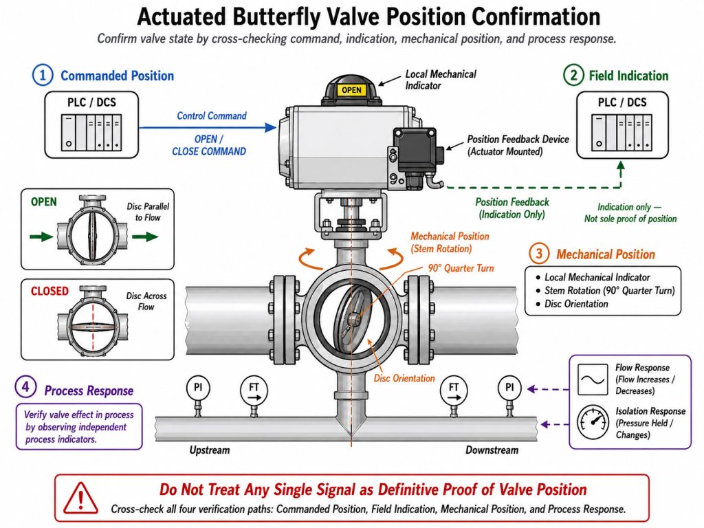
An actuated butterfly valve should be treated as confirmed only when its local mechanical indication agrees with independent feedback or the expected process response. A control-room OPEN or CLOSED command shows what the system requested, not necessarily where the disc stopped.
Four different states may appear in an automated installation:
- Commanded position: the signal sent by the control system.
- Indicated position: the local pointer, limit switch, or transmitter output.
- Mechanical position: the actual angle reached by the stem and disc.
- Sealing state: whether the closed valve meets the required leakage performance under the present differential pressure.
These states can disagree. A limit switch may change before the disc reaches its final stop, a coupling can slip, a positioner can be out of calibration, or an actuator can stall under load. Likewise, fail closed or fail open describes the intended position after loss of power or air; it does not describe the valve’s current position while the system is energized.
For pneumatic packages, compare the local indicator, end-of-travel switch, air supply condition, and process response. For electric actuators, compare the local indicator, open/close limit feedback, torque trip status, and process response. The same distinction applies when evaluating a solenoid-controlled butterfly valve package: the solenoid command and the valve position are related signals, not identical evidence.
Use a Two-Signal Position Check
The most reliable field check uses one local mechanical cue and one independent confirmation. This avoids treating an indicator, switch, or pressure reading as conclusive when that single signal can fail or be misinterpreted.
Use this matrix to choose the two signals that fit the operator:
| Operator type | First position cue | Independent confirmation | Treat the position as unconfirmed when |
|---|---|---|---|
| Manual lever | Handle and position plate | Documented stem/disc mark or expected process response | Handle and plate disagree, the handle was recently removed, or the stop does not feel normal |
| Gear operator | OPEN/CLOSED pointer and travel stop | Commissioned position switch or expected process response | Pointer reaches the mark early, resistance changes, or flow does not respond as expected |
| Pneumatic actuator | Local mechanical indicator | Limit switch/position transmitter plus process response | Air is low, the switch changes before full travel, or the actuator stalls |
| Electric actuator | Local indicator and limit status | Position feedback, torque status, and process response | A torque trip occurs, feedback freezes, or command and local indication disagree |
Apply the check in a fixed order:
- Confirm the valve tag, operator type, and intended flow path.
- Read the local mechanical position without moving the valve.
- Compare it with an independent switch, transmitter, or authorized process observation.
- If the two signals disagree, label the position unconfirmed and stop relying on it for an interlock or isolation decision.
- Inspect coupling alignment, stop adjustment, and feedback calibration only under the site’s approved operating or maintenance procedure.
For new or rebuilt valves, commissioning should verify indication at both end positions and at an intermediate point. This checks the feedback across the stroke instead of validating only one stop.
Closed Position Is Not Proven Isolation
A closed indication proves only that the operator reports the closed end of travel; it does not prove tight shutoff, zero pressure, or safe isolation. Seat damage, debris, an incorrect stop setting, a bypass path, or pressure trapped between isolation points can all leave hazardous energy in the system.
Keep three decisions separate:
- Position decision: Did the disc reach the closed end of travel?
- Leakage decision: Does the valve meet the required shutoff performance under the actual pressure and flow direction?
- Isolation decision: Has the equipment been isolated, stored pressure relieved, and the isolation verified under the site’s procedure?
Before servicing equipment or opening a line, follow the applicable energy-control procedure rather than relying on the handle or control-system status. For U.S. general-industry work within its scope, OSHA 29 CFR 1910.147 requires control of hazardous energy, treatment of stored or residual energy, and verification of isolation before work begins. Project rules may require additional isolation methods based on the fluid, pressure, and consequence of leakage.
Treat Part-Open as an Angle, Not a Flow Percentage
A part-open butterfly valve indicates disc angle, not a guaranteed percentage of flow. A 45-degree position does not mean 50 percent flow because valve geometry, available pressure drop, pipe losses, and the installed system all shape the real response.
Use position notches or actuator feedback to repeat an angle, but use the manufacturer’s Cv or Kv curve and the operating pressure conditions to estimate flow. Near the closed position, a small movement can create a large change in velocity and pressure drop; near full open, additional travel may add little useful capacity. The practical relationship is explained in more detail through butterfly valve flow characteristics.
If the valve is intended only for isolation, operate it to the correct end stop. If it is intended for modulation, verify that the valve, actuator, and control range are suitable for the expected operating angles instead of treating the handle scale as a flowmeter.
Make Position Verification Part of the Valve Package
Butterfly valve position is simple at the disc and more complicated at the operator: open aligns the disc with the pipe, closed turns it across the bore, and every external indicator is evidence that must remain correctly indexed. Use handle or pointer direction for a quick check, then add independent feedback whenever a wrong position could affect control, shutdown, or maintenance safety.
For a new valve or actuator package, specify the operator type, local indicator, fail position, limit switches or transmitter, shutoff requirement, and commissioning checks together. Contact RUITO for a project review if you want those items aligned with your media, pressure, pipe size, control duty, and documentation requirements.
FAQ
Does normally closed mean the valve is closed now?
No. Normally closed usually describes the valve’s intended fail or de-energized state; current position still requires local indication or feedback confirmation.
Is a closed butterfly valve safe to work behind?
Not on position indication alone. Closed position, shutoff leakage, and verified energy isolation are separate conditions, so follow the site’s approved isolation and lockout/tagout procedure before maintenance.
Does 50 percent open mean 50 percent flow?
No. Butterfly valve flow is generally nonlinear with disc angle and changes with the installed system, so use the applicable Cv or Kv curve and pressure conditions.