
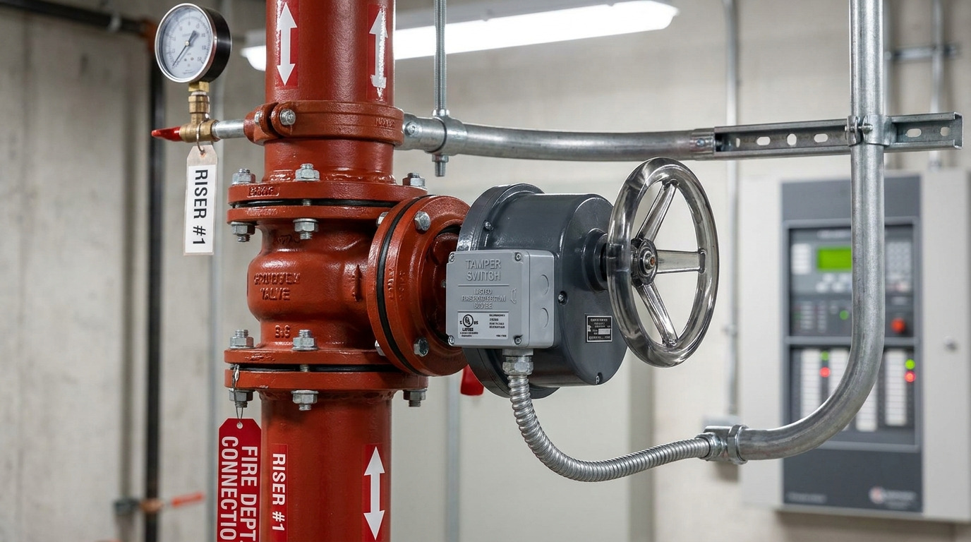
A butterfly valve tamper switch is a position-monitoring switch used with a butterfly valve to confirm that a normally open valve has not been closed or moved without notice. In fire protection systems, a butterfly valve tamper switch helps send a supervisory signal when the valve leaves its required open position, so the water supply path is not silently impaired.
It combines a quarter-turn butterfly valve with an electrical supervisory device. The valve controls the pipe opening, while the switch tells the fire alarm control panel or monitoring system whether the valve remains in the correct position.
In a real sprinkler riser room, the problem is not usually that someone cannot operate the valve. The risk is that a valve is partly closed after maintenance, struck by equipment, or adjusted without proper authorization. The tamper switch does not extinguish a fire or measure flow; it gives you early warning that the control valve may no longer be ready for service.
What a Butterfly Valve Tamper Switch Does
A butterfly valve tamper switch supervises valve position, not water movement. Its main job is to detect when a supervised-open valve is no longer fully open and send a supervisory signal before that condition becomes a system failure.
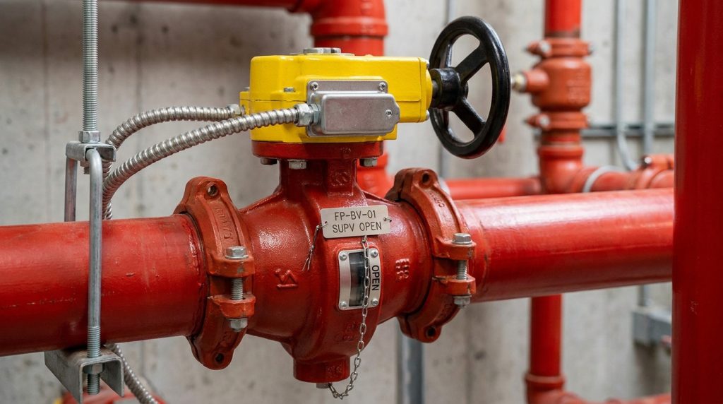
A standard butterfly valve uses a disc that rotates 90 degrees inside the pipe. In a fire protection control valve, the valve is normally kept open so water can reach sprinklers, standpipes, or other downstream equipment. The tamper switch is usually integrated into the gear operator or switch housing and responds when the valve handwheel or gear mechanism moves away from the open position.
This distinction matters because “tamper” does not always mean malicious interference. It can also mean accidental closure, incomplete reopening after inspection, vibration-related movement, or a mismatch between the valve indicator and the actual switch setting.
Key point: the device is valuable because it monitors readiness, not because it improves the hydraulic capacity of the valve.
How the Valve and Switch Work Together
The valve and switch work as one supervised assembly only when the mechanical position and electrical signal agree. If the valve is open but the switch is misadjusted, the panel may show a false supervisory condition; if the switch is adjusted poorly, the valve may move too far before the signal appears.
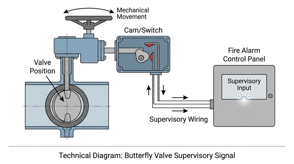
In many supervised-open butterfly valves, the handwheel drives a gearbox, and the gearbox rotates the valve disc. A cam or internal mechanism operates one or more electrical contacts. When the valve leaves the open position by a defined amount, those contacts change state and the fire alarm control unit receives a supervisory signal.
What happens when the valve moves from open?
When the valve begins to close, the switch should operate early enough to warn that the sprinkler water supply may be restricted. For NFPA-based projects, field testing commonly verifies signal receipt within one-fifth of the valve travel from the normal position for butterfly valves, subject to the adopted NFPA 72 edition and the authority having jurisdiction.
That one-fifth concept is important because a butterfly valve can reduce flow before it looks fully closed. Even a partially rotated disc creates obstruction and pressure loss. If you are reviewing a butterfly valve installed with correct alignment, the final check should include both the mechanical open indicator and the supervisory signal point.
How is it different from a waterflow switch?
A tamper switch reports valve position; a waterflow switch reports sprinkler water movement. The first is a readiness signal, while the second is normally tied to sprinkler operation.
If a control valve is closed, a waterflow switch may never see the required flow when a sprinkler opens. That is why valve supervision is treated as a separate safeguard. A tamper signal should prompt investigation, but it should not be treated the same as a confirmed waterflow alarm.
For operators, the practical rule is simple: tamper means “check the valve condition,” while waterflow means “water is moving and a fire event or test may be occurring.”
Where This Valve Is Used
A butterfly valve with a tamper switch is mainly used where a control valve must stay open and its position must be monitored. The strongest fit is water-based fire protection, especially sprinkler systems, standpipes, fire pump discharge or suction arrangements, and sectional control points.
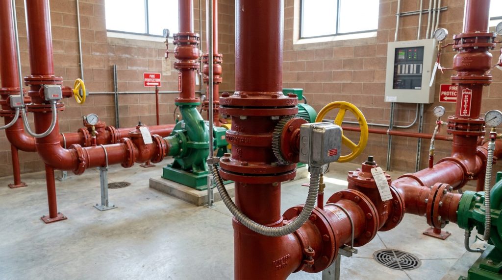
In broader industrial systems, similar valve position monitoring may also be used, but the terminology can change. Process plants may call the device a limit switch, auxiliary switch, or position feedback switch rather than a tamper switch.
Why fire sprinkler systems keep it supervised open
Fire sprinkler systems depend on available water, so a closed control valve is a serious impairment. NFPA 13 addresses supervision of sprinkler control valves, while NFPA 72 governs fire alarm signaling and monitoring concepts. In many U.S. projects, IFC Section 903.4 also drives supervision of valves controlling automatic sprinkler water supplies by a listed fire alarm control unit.
The purpose is not only code compliance. The purpose is operational readiness. A supervised-open butterfly valve helps building staff or a monitoring station see that the valve has moved before a fire exposes the problem.
When is it not the right choice?
It is not the right choice when the valve is intended for frequent throttling, modulating control, or automated process control. A fire-service supervised butterfly valve is normally selected as an indicating control valve, not as a daily flow-control device.
If you need continuous position feedback, remote actuation, or precise control, you should consider an actuated valve package with the right control accessories. A tamper switch is a supervisory device, not a substitute for a control valve actuator or a process instrumentation package.
Key Specifications to Confirm Before Selection
The safest way to select this valve is to confirm the valve rating, listing, connection, switch arrangement, and alarm interface as one package. Do not buy the valve first and treat the tamper switch as an afterthought.
For many grooved fire-protection butterfly valves, common published ranges include NPS 2 to NPS 12, or DN50 to DN300, with working pressures up to 300 psi, 2068 kPa, or 21 bar. Some high-pressure supervised butterfly valve models are published up to 365 psi, or about 25 bar. These are typical manufacturer-published ranges for specific listed products, not universal values; the final limits must come from the valve data sheet, approval listing, and project drawings.
The table below helps you separate what is usually standardized from what must be confirmed for your exact valve.
| Specification item | Typical project expectation | Why it matters | Final confirmation |
|---|---|---|---|
| Valve duty | Normally open fire protection control valve | The switch supervises readiness, not normal throttling | Valve drawing and system design |
| Size range | Often NPS 2–12 / DN50–DN300 for grooved fire-service models | Size affects pressure loss, end connection, and clearance | Manufacturer data sheet |
| Working pressure | Many listed models are up to 300 psi / 2068 kPa / 21 bar | Pressure rating must match the sprinkler or standpipe design | Listing and pressure class |
| Signal point | Commonly checked within one-fifth of travel for butterfly valves under NFPA-based testing | A late signal may allow too much closure before notification | Adopted NFPA 72 edition and AHJ |
| Switch contacts | Many assemblies use SPDT supervisory contacts; some data sheets show ratings such as 10 A at 125/250 VAC, 0.50 A at 125 VDC, and 0.25 A at 250 VDC | Electrical ratings must match the monitoring circuit | Wiring diagram and fire alarm panel requirements |
| Wiring standard | Field wiring is typically coordinated with NFPA 72 and NFPA 70 | Incorrect wiring can create false normal or false trouble signals | Electrical submittal and panel manufacturer instructions |
| Approval path | UL/cUL, FM, LPCB, VdS, or local approvals may be required depending on region | A valve acceptable in one market may not satisfy another project | Project specification and AHJ |
The most useful specification is not the longest one. It is the one that lets the contractor, fire alarm designer, and valve supplier confirm the same valve, the same switch function, and the same acceptance criteria.
Which details affect code acceptance?
Code acceptance depends on the adopted standard, the authority having jurisdiction, and the listing of both the valve and supervisory device. A valve that is mechanically suitable for water service is not automatically acceptable as a supervised fire protection control valve.
Pay attention to approval wording. “Listed butterfly valve,” “supervised open,” “fire protection service,” and “weatherproof actuator housing” each answer a different question. If the valve will be outdoors, in a humid pump room, or near washdown exposure, enclosure suitability becomes part of the selection rather than a minor accessory detail.
For fit-up, confirm face-to-face dimensions, groove or flange standard, pipe outside diameter, and operator clearance. A guide on butterfly valve sizes is useful at this stage because a correct signal cannot compensate for the wrong connection or insufficient handwheel clearance.
Installation and Wiring Checks That Matter
Installation quality decides whether the supervisory function is trustworthy. A correctly listed valve can still create unreliable signals if the switch is wired to the wrong contacts, the gearbox is rotated during installation, or the valve is not fully opened before adjustment.
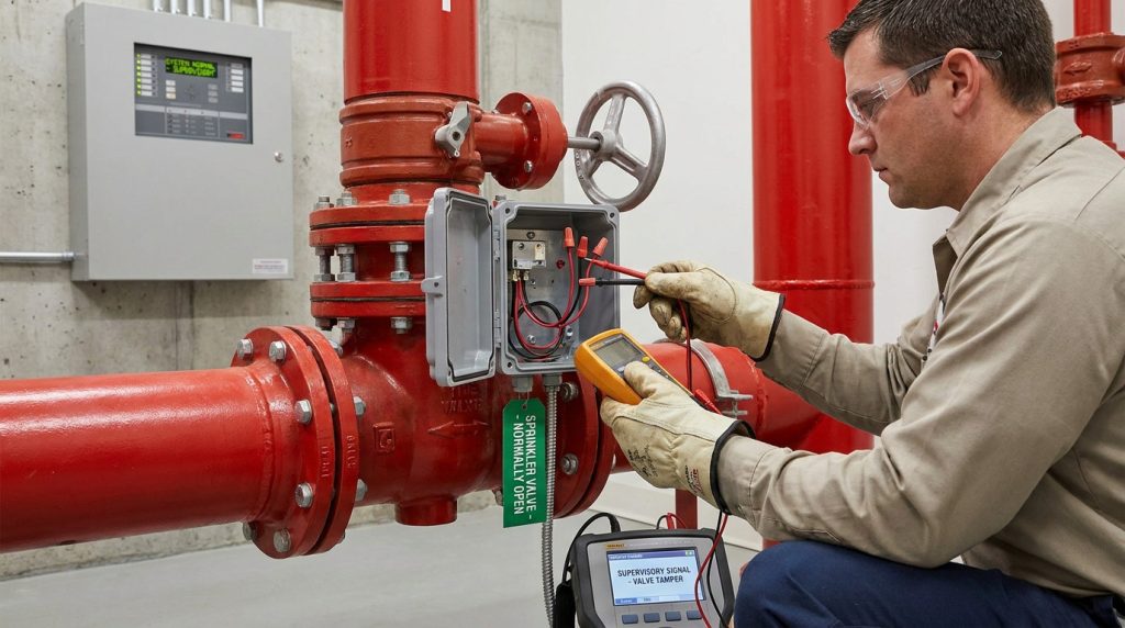
Before handover, the installer should verify the valve position indicator, the switch contact operation, the fire alarm panel response, and the reset behavior. The fire alarm contractor and sprinkler contractor should coordinate this test because the device sits between two disciplines.
Can the switch be added after mounting?
Sometimes a field-installed supervisory switch can be added, but it must be listed for the valve type and installed according to the switch instructions. For many modern fire-service butterfly valves, a factory-integrated or approved gear-operator switch package is the cleaner option because the mechanical travel and switch actuation are already designed to work together.
If you add a switch later, check the mounting bracket, cam position, conduit connection, environmental rating, and tamper-resistant cover. The question is not only “does the switch change state?” The better question is “does it change state at the required valve travel and remain reliable after normal operation?”
What should be tested before handover?
Before the system is accepted, the test should prove three things: the valve operates, the switch reports, and the panel interprets the signal correctly. Skipping any one of these creates a blind spot.
A practical handover check includes:
- Open the valve fully and confirm normal panel status.
- Rotate the handwheel toward closed and verify supervisory signal receipt.
- Confirm the signal appears early enough for the applicable code and AHJ requirement.
- Continue operation enough to confirm the signal does not falsely restore while the valve remains off-normal.
- Reopen the valve fully and verify proper reset at the panel.
- Confirm unused conductors are capped and field wiring follows the approved diagram.
This is also the right time to check nameplate data, valve tag numbers, and panel point labels. If the panel label says “Zone 2 riser valve” but the device is installed on a different branch, the signal may be technically correct but operationally confusing.
Maintenance Signals and Troubleshooting Clues
A tamper signal should be treated as a valve readiness issue until proven otherwise. The cause may be a partly closed valve, a switch adjustment problem, damaged wiring, a loose cover, or an issue inside the monitoring circuit.
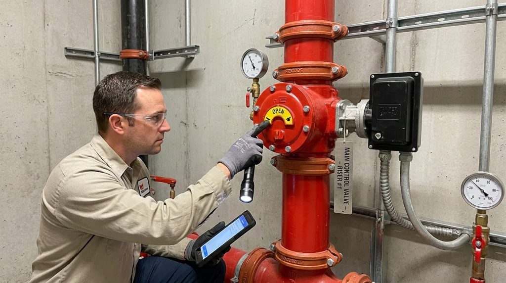
Routine inspection under NFPA-based programs often includes confirming that control valves are open, accessible, properly identified, and free from damage or tampering. Valve supervisory signal devices are commonly tested on a semiannual schedule under NFPA 25 and NFPA 72 based programs, but the final frequency depends on the adopted editions and local enforcement.
How do you separate valve, switch, and wiring issues?
Start with the physical valve position before assuming an electrical fault. If the indicator and handwheel show the valve is not fully open, restore the valve only under the facility’s impairment and authorization procedure. A closed sprinkler control valve can affect life safety, so it should not be treated like an ordinary maintenance nuisance.
If the valve is fully open but the supervisory signal remains active, the likely causes shift toward switch adjustment, damaged contacts, wiring, or panel interpretation. For a shut-off butterfly valve, maintenance work should also check operator smoothness, disc movement, seat condition, external corrosion, and whether the valve can reach the full-open stop without forcing.
Do not defeat the switch to clear the signal. A bypassed supervisory device may hide the exact condition it was installed to detect.
Common Specification Mistakes to Avoid
Most problems come from treating the tamper switch as a small accessory instead of a monitored safety function. If the valve, switch, alarm panel, and project code basis are not reviewed together, the system may pass a visual check but fail the real readiness requirement.
Common mistakes include:
- Selecting a general-purpose butterfly valve without fire protection listing.
- Using a switch that is not approved for the valve or operator style.
- Assuming a tamper signal is the same as a waterflow alarm.
- Ignoring pressure rating differences between 300 psi and higher-pressure systems.
- Forgetting outdoor or corrosive environmental conditions.
- Failing to confirm whether the valve supervises only the open position.
- Ordering the wrong end connection for grooved, wafer, lug, or flanged piping.
- Leaving panel labels too vague for facility staff to locate the valve quickly.
The best prevention is a coordinated submittal. Include valve size, pressure rating, connection type, body and seat material, approval listing, switch contact rating, wiring diagram, valve tag, and intended panel point description. For project-related values such as pressure rating, end-to-end dimensions, electrical ratings, and switch actuation point, use the typical ranges only as a screening guide and confirm the final values against the valve drawing and data sheet.
Conclusion
A butterfly valve tamper switch is a supervised position device that helps confirm a normally open valve remains ready for service. It is especially important in fire protection systems because the water supply can be impaired by a partly closed control valve long before anyone sees a visible problem.
For a reliable selection, you need more than the keyword “tamper switch.” Confirm the valve listing, size, pressure rating, connection, switch function, wiring requirements, signal point, and local code acceptance path. If you are comparing supervised butterfly valves for a project, you can discuss your valve specification with the required service conditions, drawings, pressure class, and monitoring requirements so the valve package can be reviewed against the application.
FAQ
Can I use a normal butterfly valve with a tamper switch?
Usually no for fire protection unless the valve and switch are listed and accepted for that purpose. A general industrial butterfly valve may control flow, but it may not meet the listing, supervision, or signaling requirements for sprinkler control valve service.
What’s the best valve position for the tamper switch to monitor?
The best position is normally the fully open position. In sprinkler and standpipe systems, the key risk is loss of water supply, so the switch should report when the valve moves away from its required open condition.
How do I know if a tamper signal means the valve is closed?
You do not know from the signal alone. A tamper signal means the supervised condition is off-normal, so you should check the valve position, indicator, handwheel, switch housing, wiring, and panel label before deciding whether the valve is actually closed or the signal is caused by an electrical issue.
Can I use this valve for throttling water flow?
Not in normal fire protection service. A supervised-open fire protection butterfly valve is intended to remain open, while throttling applications need a valve and control approach designed for regular position changes, pressure loss, and control stability.
What’s the best information to provide before ordering one?
Provide the pipe size, connection type, working pressure, valve material, seat material, indoor or outdoor location, required approvals, fire alarm panel interface, wiring preference, and project standard. Final dimensions and electrical ratings should always be confirmed by the manufacturer’s drawing and data sheet.