
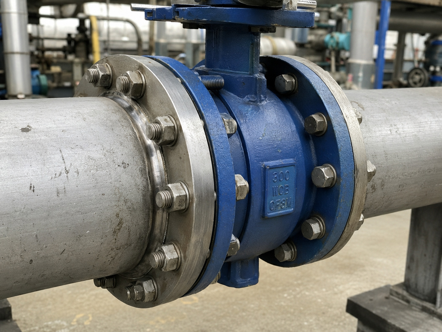
Use the Class 300 butterfly valve bolt chart below to match NPS, per-flange hole count, bolt diameter, hole diameter, and bolt circle—but do not release bolt length until you verify the valve body and gasket stack. A 300 butterfly valve bolt chart solves the drilling-pattern question; it does not, by itself, define the finished bolting package.
That distinction matters when an installer has the correct bolt diameter but still finds that a wafer stud is too short, a lug cap screw bottoms in a blind hole, or the purchased quantity does not match the joint. Before ordering fasteners for industrial butterfly valve configurations, confirm the flange standard, pressure class, body style, approved drawing, gasket, and assembly procedure.
Confirm What “300” Means Before Reading the Chart
In this context, “300” means ASME pressure Class 300; it does not mean DN300 or a universal 300 psi rating. Pressure-temperature capability depends on the valve design, body and seat materials, temperature, and governing valve standard.
ASME B16.5 covers Class 300 flange dimensions, bolting, gaskets, and joints from NPS 1/2 through NPS 24. The table below focuses on common butterfly valve sizes from NPS 2 through NPS 24.
Class 300 and DN300 are different inputs
DN300 is a metric nominal size commonly associated with NPS 12, while Class 300 is a pressure class. A DN300 PN16 flange, a DN300 PN25 flange, and an NPS 12 Class 300 flange do not share one drilling pattern. If a request says only “300 butterfly valve,” obtain the size system, flange standard, and pressure designation before using any row.
Class 300 Butterfly Valve Bolt Chart by NPS
This chart gives the ASME B16.5 Class 300 mating-flange pattern, not a universal butterfly valve bolt length. “Holes per flange” is the number of positions in one pipe flange; the number of fasteners you buy changes with wafer, lug, or double-flanged construction.
| NPS | Holes per flange | Nominal bolt diameter and thread | Bolt-hole diameter | Bolt-circle diameter |
|---|---|---|---|---|
| 2 | 8 | 5/8-11 UNC | 3/4 in. | 5.00 in. |
| 2-1/2 | 8 | 3/4-10 UNC | 7/8 in. | 5.88 in. |
| 3 | 8 | 3/4-10 UNC | 7/8 in. | 6.62 in. |
| 3-1/2 | 8 | 3/4-10 UNC | 7/8 in. | 7.25 in. |
| 4 | 8 | 3/4-10 UNC | 7/8 in. | 7.88 in. |
| 5 | 8 | 3/4-10 UNC | 7/8 in. | 9.25 in. |
| 6 | 12 | 3/4-10 UNC | 7/8 in. | 10.62 in. |
| 8 | 12 | 7/8-9 UNC | 1 in. | 13.00 in. |
| 10 | 16 | 1-8 UNC | 1-1/8 in. | 15.25 in. |
| 12 | 16 | 1-1/8-8 UN | 1-1/4 in. | 17.75 in. |
| 14 | 20 | 1-1/8-8 UN | 1-1/4 in. | 20.25 in. |
| 16 | 20 | 1-1/4-8 UN | 1-3/8 in. | 22.50 in. |
| 18 | 24 | 1-1/4-8 UN | 1-3/8 in. | 24.75 in. |
| 20 | 24 | 1-1/4-8 UN | 1-3/8 in. | 27.00 in. |
| 24 | 24 | 1-1/2-8 UN | 1-5/8 in. | 32.00 in. |
For example, the NPS 8 row establishes 12 flange positions and 7/8-9 UNC bolting. It does not tell you whether the installed valve needs 12 through-studs, 24 cap screws, or a mixture of long and short fasteners around the neck or retainer. The approved valve drawing must answer that second question.
Convert Flange Holes Into the Correct Purchase Quantity
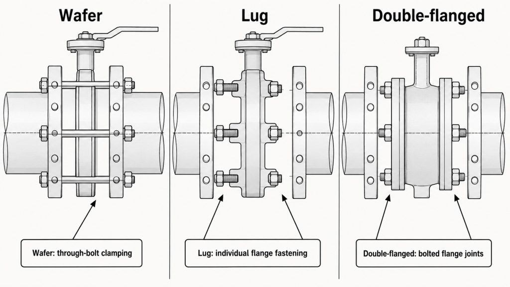
Purchase quantity depends on how the valve body receives the fasteners, so never copy “holes per flange” directly into a bill of materials. The following conversion prevents the most common counting error.
| Valve body | How the joint is fastened | Starting quantity rule | Drawing check |
|---|---|---|---|
| Wafer, all-through | Studs or bolts pass through both pipe flanges and the valve body | Usually one fastener per flange-hole position | Look for neck obstructions, centering features, or blind/tapped positions |
| Lug, both sides connected | Separate cap screws or studs enter the valve lugs from each pipe flange | Usually two fasteners per flange-hole position | Confirm tapped-hole thread, usable depth, retainer-side differences, and dead-end rating |
| Double-flanged | Each valve flange forms its own bolted joint with a pipe flange | One complete flange set per side | Verify valve-flange drilling and thickness on each side |
| Hybrid or blind-hole design | Long through-fasteners and shorter fasteners are mixed | No safe multiplier | Use the drawing’s position-by-position schedule |
The important distinction is between flange positions and physical fastener pieces. An all-through wafer joint may use one long stud across a position, while a fully lugged joint normally uses one fastener from each side at that same position. Some high-performance bodies interrupt through-bolting near the shaft neck or seat retainer, so even the wafer rule can have exceptions.
For a broader body-style decision, review the practical differences in wafer-versus-lug body selection. Do not assume that a lug valve is suitable for one-sided pressure merely because it has threaded lugs; dead-end pressure capability is a separate valve rating.
Calculate Length From the Actual Joint Stack-Up
Final bolt length comes from the real clamp stack, fastener type, and required engagement—not from pressure class alone. Record every thickness from the approved drawings before rounding to an available fastener length.
Wafer through-stud or through-bolt
For a stud with nuts at both ends, add both pipe-flange thicknesses, both gaskets, valve face-to-face thickness at the bolt path, washers, both nut heights, and the specified thread projection. A machine bolt uses an under-head length, so include the clamped components, washer and nut allowance, and the required projection beyond the nut; do not add the bolt head thickness.
If the body blocks through-bolting at selected positions, calculate the long and short groups separately. A general flange-to-flange stud chart cannot capture that geometry.
Lug cap screw or stud
For a lug cap screw, add the pipe-flange thickness, gasket, washer, and required thread engagement in the lug, plus any retainer-side offset shown on the drawing. Then compare the result with usable tapped depth. Too little engagement risks thread failure; too much length can bottom in a blind hole before the joint develops gasket load.
A butterfly valve cap screw chart can organize size, thread, and length data, but the drawing must still define the engagement and blind-hole limits for the specific valve.
Separate Dimensional Data From Material and Torque Decisions
The flange chart controls fit, but it cannot select the fastener grade, coating, lubricant, gasket, or tightening torque. Those choices depend on design pressure and temperature, flange and valve materials, corrosion exposure, gasket stress, thread condition, and the project specification.
ASTM A193/A193M covers alloy-steel and stainless-steel bolting for high-temperature or high-pressure service and other special applications. A193 B7 studs with compatible A194 2H nuts are common in carbon-steel pressure joints, while stainless grades may be considered for corrosive service. Neither choice is automatic: low-temperature duty, chloride exposure, galling risk, coating, and lubricant can require a different material system.
Gasket thickness directly changes calculated length, and gasket construction changes the required assembly load. Confirm butterfly valve gasket selection before freezing the bolt schedule. Do not publish one universal Class 300 torque value: the same diameter can require a different torque when grade, lubrication, surface condition, or gasket changes.
For pressure-boundary joints, ASME PCC-1 provides guidance for developing assembly procedures, including joint preparation, gasket and bolting practices, tightening patterns, and troubleshooting. Your approved project procedure remains the controlling instruction at site.
Release the Bolting Package Through a Six-Check Gate
Release fasteners only when the chart, valve drawing, joint materials, and installation procedure agree. Use this gate for a purchase requisition, drawing review, or pre-installation check:
- Identity: Match NPS, Class 300, ASME B16.5, flange facing, and the standard edition named by the project.
- Body geometry: Confirm wafer, lug, or double-flanged construction; face-to-face dimension; drilling; neck or retainer obstructions; and all tapped or blind-hole locations.
- Joint stack: Record flange, gasket, washer, nut, and valve-body thicknesses at every distinct bolt path.
- Fastener specification: State bolt or stud type, diameter, thread series, grade, nut grade, coating, lubricant, and washer requirement.
- Length and quantity: Calculate each length group, verify thread engagement and projection, check for bottoming, and total the physical fasteners rather than counting flange holes alone.
- Assembly control: Issue the tightening sequence, target load or approved torque, inspection points, and acceptance record.
At site, complete the flange alignment checks before applying final load. Fasteners must not be used to pull misaligned piping into position. Hand-snug the joint, confirm centering and disc clearance, then tighten with the approved pattern and staged passes.
Red flags that should stop release include a request that says only “300,” a bolt length copied from a plain flange-pair chart, no valve drawing revision, a lug schedule without usable thread depth, mixed inch and metric threads, or a torque value with no grade and lubrication basis. Each signals that the package is still an assumption rather than a verified joint.
Specify the Joint, Not Just the Bolts
A reliable Class 300 bolting package starts with the correct ASME flange row, then resolves body-style quantity, joint stack-up, material, gasket, and assembly control. The chart is the dimensional baseline; the approved valve drawing and project bolting procedure turn it into an installable specification.
RUITO can review higher-pressure butterfly valve requirements, flange compatibility, drawings, materials, and inspection documents before production. To check a Class 300 application, send the project data to our engineering team with the NPS, flange standard and facing, valve body style, gasket details, fastener specification, and current drawing.
FAQ
Can I use metric bolts in ASME Class 300 tapped lugs?
Not unless the approved valve drawing specifies matching metric threads. ASME B16.5 lists flange bolt and hole diameters in inch units, and a metric fastener must never be forced into an inch-series tapped lug even if its outside diameter appears close.
What should I submit for a bolt-length review?
Submit the valve general arrangement drawing, mating-flange standard and facing, gasket type and thickness, washer arrangement, fastener type, nut requirement, and required thread engagement or projection. Also identify any shaft-neck or retainer positions that prevent through-bolting.
Does dead-end service change the bolt count or valve rating?
It can change the installed-side quantity, but it does not create a dead-end rating. When one pipe flange is removed, only the connected-side fasteners remain; the valve must have a documented one-sided pressure rating for that direction and service condition.