
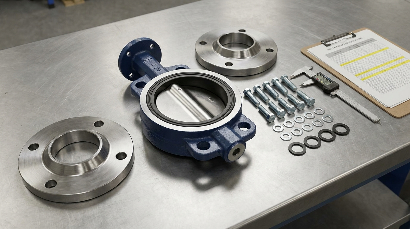
A lug style butterfly valve bolt chart is read by matching the valve NPS, flange class, and flange standard to the required bolt count, bolt diameter, and lug engagement limits before you select the final bolt length. For a lug style butterfly valve, the chart is only the starting point because the valve body has threaded lugs, so bolt length must be confirmed against the valve drawing, not copied from a through-bolt flange chart.
If you are replacing a valve in a water line, HVAC loop, or process skid, the common problem is simple: the flange bolt pattern looks standard, but the bolts either bottom out in the lug or fail to engage enough thread. This article shows you how to use the chart correctly, where standard flange data ends, and what you should confirm before ordering a butterfly valve or installing one in the line.
What a Lug Style Butterfly Valve Bolt Chart Tells You
A lug style butterfly valve bolt chart tells you the flange bolting pattern and the bolt size that must match the piping flange. The chart should help you confirm the nominal pipe size, pressure class, number of bolts, bolt diameter, and sometimes the bolt circle or flange hole diameter.
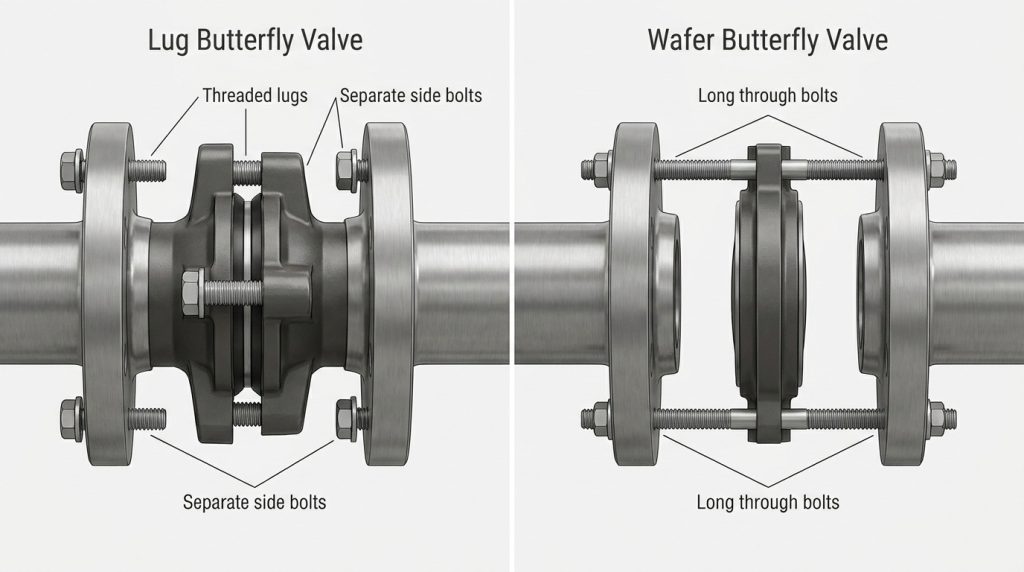
The key point is that a lug body is not bolted the same way as a wafer body. A wafer valve is usually clamped between two flanges with long bolts or studs passing around the body. A lug valve has threaded inserts or cast lugs in the valve body, so each side of the pipe flange is usually bolted into the valve body from its own side.
Why Is Lug Bolting Different From Wafer Bolting?
Lug bolting is different because the load path stops inside the valve body instead of passing through the whole flange joint. That makes thread engagement, tapped hole depth, and bolt end clearance more important than they are on a wafer valve.
For normal two-flange installation, both sides are bolted to the valve. For dead-end service, one downstream pipe section may be removed while the valve remains attached on the other side, if the valve design and pressure rating allow it. That is why a lug valve chart must be read with the valve datasheet, not only with a generic flange chart.
What Is Usually Missing From Generic Charts?
Generic flange charts usually give bolt diameter and quantity, but they often do not give the correct machine bolt length for a lug valve. Stud bolt lengths in many flange charts are intended for flange-to-flange bolting with nuts, not for bolts threaded into a valve body.
A useful lug bolt callout should confirm:
- Flange standard, such as ASME B16.5 or EN 1092-1
- Pressure class or PN rating
- NPS or DN size
- Bolt quantity per side
- Bolt diameter and thread series
- Minimum and maximum usable bolt length
- Bolt material, coating, and nut or washer requirements where applicable
Key takeaway: the chart identifies the bolting pattern; the valve drawing confirms the safe bolt length.
Start With Flange Standard, Class, and NPS
The first step is to identify the flange standard, pressure class, and NPS before looking at bolt size. ASME B16.5-2025 covers pipe flanges and flanged fittings from NPS 1/2 through NPS 24, with bolt and bolt hole diameters expressed in inch units. For larger steel flanges, ASME B16.47-2025 covers NPS 26 through NPS 60.
For common ASME Class 150 lug butterfly valves, the following reference values help you check whether the flange pattern is in the expected range. This table is a selected ASME B16.5 Class 150 reference for common butterfly valve sizes, not a final lug bolt length table.
| Valve NPS | Class 150 bolt quantity | Bolt diameter | Bolt hole diameter |
|---|---|---|---|
| 2 | 4 | 5/8 in | 0.75 in |
| 3 | 4 | 5/8 in | 0.75 in |
| 4 | 8 | 5/8 in | 0.75 in |
| 6 | 8 | 3/4 in | 0.88 in |
| 8 | 8 | 3/4 in | 0.88 in |
| 10 | 12 | 7/8 in | 1.00 in |
| 12 | 12 | 7/8 in | 1.00 in |
The pattern changes with size, so do not assume that a larger valve simply uses the same bolt count with a longer bolt. When the project is specifically ASME Class 150, a 150 butterfly valve bolt chart helps you stay within the right class instead of mixing values from another pressure rating.
Can You Use a Class 150 Chart for Class 300?
No, you should not use a Class 150 chart for a Class 300 flange, even if the valve size is the same. Class 300 flanges usually have different bolt quantities, bolt diameters, flange thicknesses, and bolt circles.
For example, under ASME B16.5 reference data, NPS 4 Class 150 uses 8 bolts at 5/8 in diameter, while NPS 4 Class 300 uses 8 bolts at 3/4 in diameter. That difference affects the lug thread, the required bolt diameter, and the valve body drilling pattern. If the line is Class 300, use an ASME Class 300 butterfly valve bolt chart instead of adapting Class 150 values.
How to Turn the Chart Into a Lug Bolt Callout
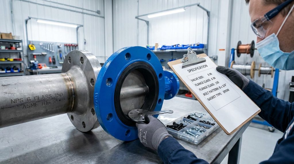
The correct lug bolt callout should combine the flange chart with the valve manufacturer’s tapped-lug details. In practice, you are not just asking, “What bolt size fits this flange?” You are asking, “What bolt size fits the flange and safely engages the valve body without bottoming out?”
A practical lug bolt callout may look like this in a project note: ASME B16.5 Class 150, NPS 6, 8 bolts per flange side, 3/4 in UNC bolts, material per project specification, final length per valve drawing. The bolt diameter and quantity come from the flange standard; the final length comes from the valve body, gasket, washer, and flange thickness.
What Does Bolt Count Per Side Mean?
Bolt count per side means each flange side is bolted independently into the valve body. If a chart says an NPS 6 Class 150 flange uses 8 bolts, a lug valve installation normally uses 8 bolts on the upstream side and 8 bolts on the downstream side, not 8 total for the whole assembly.
This matters during ordering because a buyer may count flange holes but forget that the lug valve needs separate bolts from both sides. It also matters during installation because one side may require shorter or longer bolts if flange thickness, gasket type, or accessories differ.
How Do You Estimate Length Before the Drawing Arrives?
You can estimate bolt length by adding the flange thickness, gasket compression allowance, washer thickness if used, and required thread engagement into the lug. Then check that the selected bolt does not bottom out in the tapped hole.
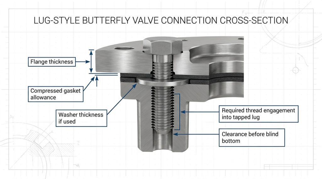
Use this only as an estimating method. The final value must be confirmed by the valve drawing or datasheet because lug depth, liner thickness, body material, and drilling depth vary by valve design. A lug style butterfly valve bolt chart that gives only flange data cannot safely replace that dimensional check.
Bolt Material, Coating, and Thread Form Matter
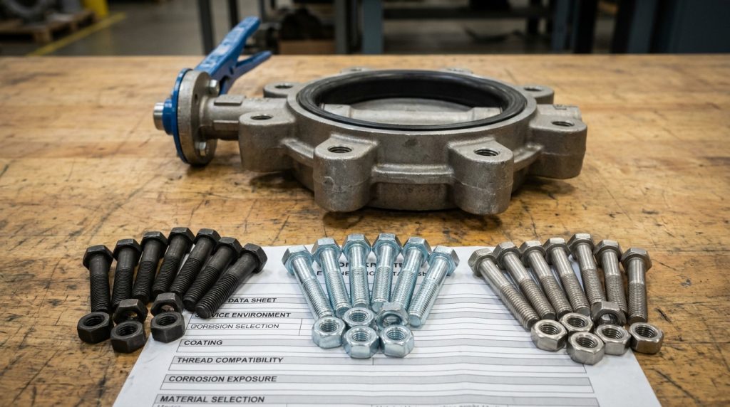
The bolt chart gives geometry, but it does not fully select bolt material or coating. For many carbon steel flange joints, ASTM A193 B7 studs with ASTM A194 2H nuts are a common high-strength bolting combination; however, a lug valve using machine bolts into tapped lugs may require a different bolt form or coating depending on the service.
For water, wastewater, HVAC, and general industrial service, carbon steel or zinc-coated bolting may be acceptable where corrosion risk is moderate and the project specification allows it. For chemical service, marine exposure, outdoor corrosive conditions, or stainless piping, stainless or coated bolting may be needed to reduce seizure, corrosion, or galvanic mismatch.
When Is B7 With 2H Enough?
B7 with 2H is often used for pressure piping flange assemblies, but it is not automatically the right answer for every lug body. If the valve uses cap screws threaded directly into lugs, the project should confirm bolt grade, thread fit, coating, and whether nuts are used at all.
The safe approach is to treat ASTM grade as part of the full bolting specification, not as a substitute for dimensional fit. A strong bolt that is too short, too long, or incompatible with the lug thread can still create a leak or damage the valve body.
When Do You Move to Stainless Bolting?
You move to stainless bolting when corrosion resistance is more important than using a standard carbon steel bolting package. Common stainless options include ASTM A193 B8 or B8M bolting, depending on the environment and project requirements.
Stainless bolting can also introduce galling risk, especially when stainless threads are tightened without suitable lubrication or coating. If stainless bolts thread into stainless or corrosion-resistant lugs, confirm the anti-galling practice and torque method before installation.
Torque Values Need a Separate Assembly Decision
Torque should not be copied from a lug style butterfly valve bolt chart unless the chart is issued for the exact valve, gasket, bolt grade, lubricant, and flange condition. Torque is a method for creating bolt load, and bolt load is what compresses the gasket and holds the joint.
ASME PCC-1 is commonly used as a guideline for pressure-boundary bolted flange joint assembly. It is useful because it treats flange assembly as a controlled process, not a single torque number. For lug butterfly valves, this matters because uneven tightening can distort the body, over-compress an elastomer seat, or pull one side of the joint out of alignment.
Why Does Lubrication Change Torque?
Lubrication changes torque because it changes friction in the threads and under the bolt head or nut face. The same torque can produce different bolt loads on dry, zinc-coated, PTFE-coated, or lubricated bolting.
That is why a torque table must state its assumptions. If the project changes from dry carbon steel bolts to lubricated stainless bolts, the original torque value may no longer produce the intended clamp load.
What Tightening Pattern Reduces Leakage Risk?
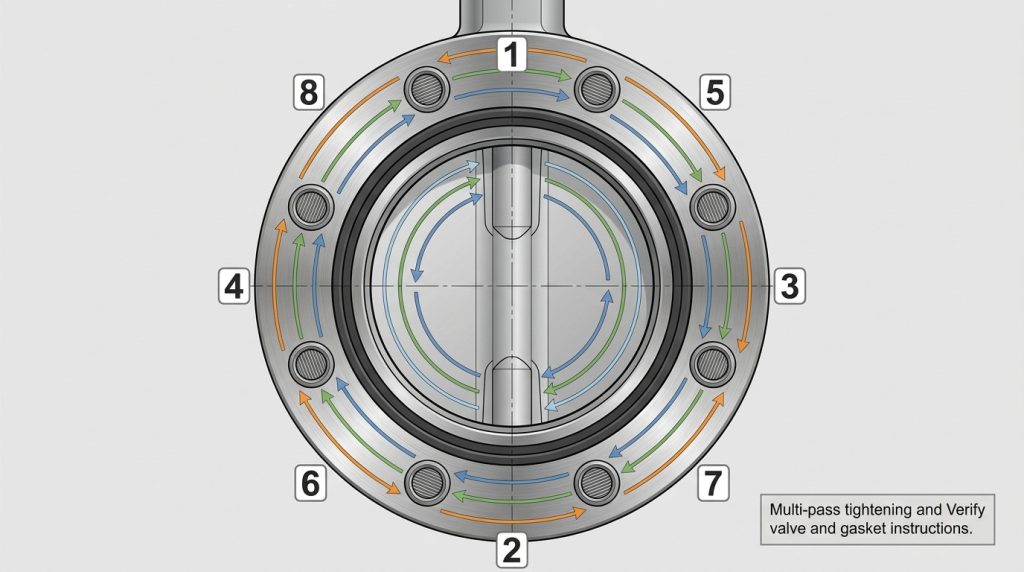
A cross-pattern, multi-pass tightening method reduces the risk of uneven gasket compression. The goal is to bring the flanges together evenly instead of fully tightening one side while the opposite side is still loose.
For resilient seated butterfly valves, also check disc clearance before final tightening. The disc should not scrape the pipe bore, gasket inner diameter, or flange face during operation.
Where Lug Bolt Charts Fail in Real Projects
Lug bolt charts fail when the flange pattern is treated as the whole installation specification. The highest-risk cases are not usually standard clean installations; they are replacements, mixed-standard systems, dead-end service, and projects where the existing flange data is incomplete.
Watch these conditions carefully:
- The pipe flange is EN, JIS, or another standard, but the valve chart is ASME.
- The valve is NPS-sized, but the project documents list DN only.
- The valve is lined, and the liner changes face-to-face or gasket behavior.
- The bolt is long enough to hit the bottom of the tapped lug.
- The bolt is too short to achieve reliable thread engagement.
- One side of the valve may be removed for dead-end service.
- Old flanges are corroded, distorted, or not drilled to the expected pattern.
For dead-end service, verify flow direction, pressure limit, flange side, and bolting sequence instead of relying on the chart alone; a lug style butterfly valve installation check is the right next step when one side of the piping may be removed.
Why Replacement Jobs Need Extra Checks
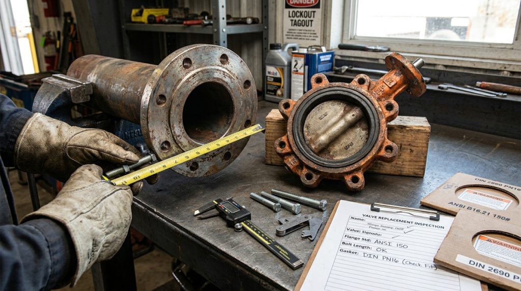
Replacement jobs need extra checks because the existing valve may not match the drawing, nameplate, or purchase record. Older systems may have mixed flange standards, nonstandard bolt lengths, or field-modified hardware.
If you are checking a specific 8-inch valve, do not interpolate from a 6-inch or 10-inch chart. A dedicated 8 butterfly valve bolt size check is safer because NPS 8 has its own bolt count, bolt diameter, and flange pattern.
Quick Checklist Before Ordering or Installing
The best way to avoid bolt mistakes is to treat the chart as one input in a short verification process. Before ordering bolts or installing the valve, confirm the flange data, valve body data, and assembly data together.
Use this checklist:
- Confirm valve type: lug, wafer, semi-lug, or flanged.
- Confirm NPS or DN and pressure class or PN rating.
- Confirm flange standard, such as ASME B16.5, ASME B16.47, EN 1092-1, or JIS.
- Match bolt quantity and diameter to the flange standard.
- Confirm thread series, such as UNC for many ASME bolting applications.
- Confirm bolt material and coating against service conditions.
- Confirm bolt length from flange thickness, gasket, washer, and lug depth.
- Check that bolts do not bottom out in the lug.
- Confirm torque assumptions, lubricant, and tightening sequence.
- Keep the valve drawing or datasheet with the installation record.
This process may feel slower than reading one line from a chart, but it prevents the two failures that cause most trouble: insufficient engagement and overlong bolts bottoming in the body.
Conclusion
A lug style butterfly valve bolt chart helps you identify the correct flange bolting pattern, but it does not complete the whole bolting decision by itself. You still need to confirm the flange standard, pressure class, NPS, bolt diameter, thread form, material, torque assumptions, and valve-specific lug depth before choosing the final bolt length.
For a new project, replacement valve, or uncertain flange match, send the valve size, flange standard, pressure class, gasket type, service conditions, and any available drawings through contact Ruitoflow so the bolting fit can be reviewed against the valve configuration you plan to use.
FAQ
Can I use standard flange bolts on a lug butterfly valve?
Yes, but only if the bolt diameter, thread form, length, and material match the lug valve drawing. Standard flange charts help with bolt diameter and quantity, but lug valves also require safe thread engagement into the valve body.
What is the best way to choose lug valve bolt length?
The best way is to calculate an estimate, then confirm it with the valve drawing. Add flange thickness, gasket allowance, washer thickness if used, and required lug engagement, then check that the bolt will not bottom out.
How do I know if my chart is for lug or wafer valves?
Check whether the chart lists separate lug bolt lengths or only through-bolt and stud lengths. If it only shows long studs with nuts for both sides, it may be a flange or wafer-style reference rather than a lug-specific bolt length chart.
Can I use a Class 300 bolt chart on a Class 150 valve?
No, you should match the chart to the actual flange class. Class 150 and Class 300 flanges can use different bolt diameters, quantities, hole sizes, and bolt circles, so mixing charts can cause a serious fit error.
How do I know if dead-end service is allowed?
Check the valve datasheet and pressure rating for dead-end service before relying on the lug design. A lug body can support one-sided bolting in some configurations, but the allowable pressure, flow direction, and installation limits must come from the valve manufacturer’s documentation.