
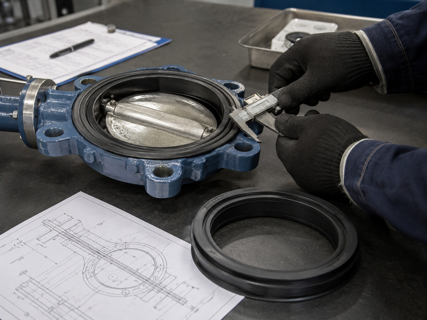
Reliable butterfly valve seals come from matching the sealing element to the valve geometry, the full service envelope, and a defined acceptance test—not from choosing an elastomer name alone. A seat marked EPDM or FKM can still leak if its profile does not match the body groove, the disc edge is damaged, the pressure direction is wrong, or the cleaning cycle exceeds the compound’s limits.
That is why a replacement request based only on nominal valve size often produces the wrong part. If you are sourcing a complete valve rather than a spare seal, first review the available industrial butterfly valve configurations and identify the exact design that establishes shutoff.
This article gives you a practical way to define the sealing boundary, screen materials, diagnose the existing failure, and turn operating data into an orderable specification.
Define the Seal Boundary Before Choosing a Material
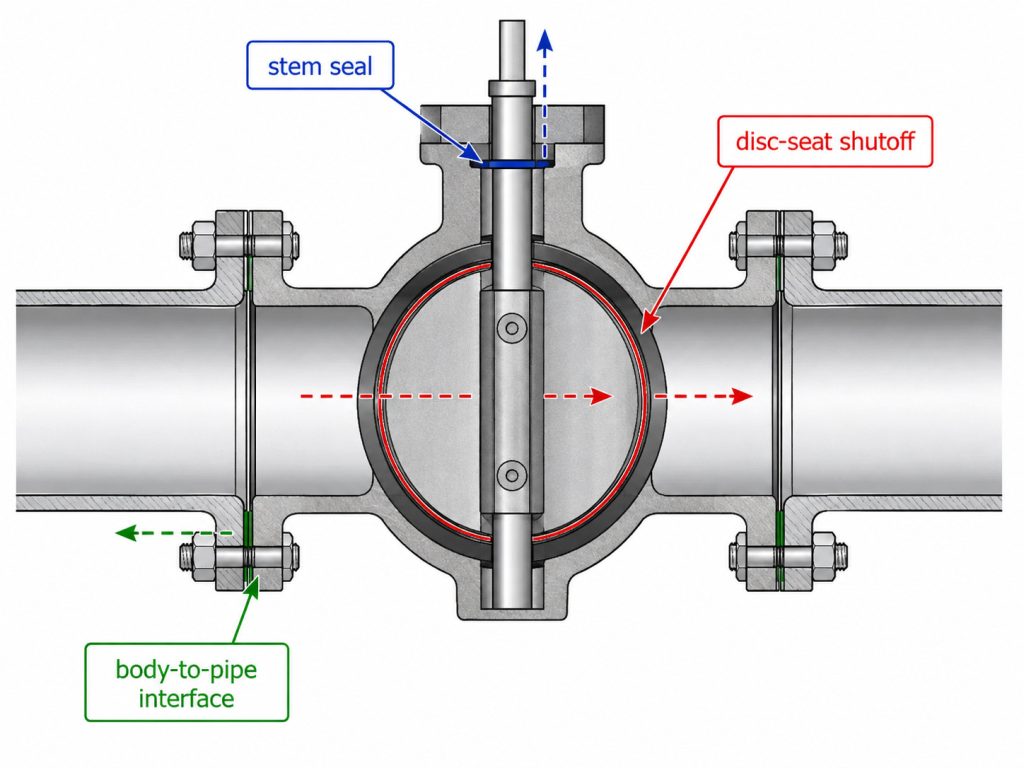
A butterfly valve can leak across the closed disc, around the stem, or at the pipe connection, and each path involves a different sealing component. Calling every one of these parts a “butterfly valve seal” can send maintenance teams toward the wrong repair.
The primary shutoff seal is the contact between the disc and seat. In many concentric resilient-seated valves, a molded or replaceable elastomer liner forms this seat and may also isolate the body from the process fluid. Offset designs more often use a distinct resilient, polymer, laminated, or metal seat ring engineered for a specific disc geometry and pressure direction.
Stem packing, O-rings, or other shaft seals control external leakage along the stem. The body-to-pipe interface may depend on the liner’s molded flange faces, a separate gasket, or a manufacturer-specific arrangement. Before adding another gasket, confirm the intended joint design; this overview of butterfly valve gasket selection and leak prevention explains why an incorrect interface can create rather than cure leakage.
The first diagnostic question is therefore not “Which rubber do I need?” It is “Where is the fluid escaping, and which component is responsible for that boundary?”
Start With Valve Geometry and Replacement Fit
Replacement fit is controlled by the valve series and sealing geometry, not by nominal line size alone. Two DN100 or 4-inch seats can have different body grooves, stem passages, widths, lip profiles, disc diameters, and compression requirements.
Identify the valve design
Record whether the valve is concentric, single-, double-, or triple-offset; wafer, lug, or flanged; and resilient-, PTFE-, or metal-seated. Also record whether shutoff is required in one direction or both. These details define how the disc approaches the seat and how differential pressure energizes or unloads the sealing contact.
For a spare seat or seal ring, capture the manufacturer, model or series, serial number, nominal size, pressure class, and drawing revision. If the nameplate is unreadable, measure the body recess, seat width and thickness, stem-hole geometry, disc outside diameter, and disc-edge profile against a controlled drawing. A photograph helps identify the part, but it does not replace dimensions.
Inspect the mating hardware
A new seat cannot compensate for a nicked disc edge, bent shaft, worn bearing, corroded retainer, or actuator stop that prevents full closure. Check disc runout, shaft alignment, seating-surface damage, retainer condition, and the open and closed stop settings before ordering the replacement.
This fit check changes the purchasing decision. If the original geometry is intact, a like-for-like seat may restore shutoff; if the metal interfaces are damaged or unidentified, a complete valve or an engineered retrofit is usually more controllable than a guessed spare.
Match the Material to the Whole Service Envelope
Material selection must cover process media, cleaning media, normal temperature, upset temperature, differential pressure, vacuum, solids, and operating frequency. A compatibility label based on the main fluid alone is incomplete.
Use the following matrix as a screening tool, then confirm the exact compound and construction with the supplier’s data for your stated conditions.
| Material family | Typical starting point | Conditions that need explicit review | Procurement note |
|---|---|---|---|
| EPDM | Water, HVAC water, and many aqueous services | Oils, fuels, concentrated chemicals, oxidants, steam or cleaning temperature | Specify the actual compound and any potable-water or process approval required |
| NBR | Oil-bearing media, fuels, and general industrial service | Ozone exposure, weathering, hot water, steam, and aggressive chemicals | Do not treat all nitrile compounds as interchangeable |
| FKM | Many oils, fuels, chemicals, and elevated-temperature duties | Hot water, steam, amines, low-temperature flexibility, and rapid decompression | Verify the grade, temperature cycle, and chemical concentration |
| PTFE-based seat | Broad chemical service and higher-temperature duties | Seat elasticity, cold flow, abrasives, operating torque, and supported-seat design | Order the complete engineered seat construction, not “PTFE” as a loose material callout |
| Metal or laminated seal | High temperature, erosive service, or offset-valve duties | Required leakage rate, pressure direction, thermal cycling, surface finish, and actuator torque | State the valve design and acceptance criterion; do not assume soft-seat tightness |
The key decision from the matrix is that the polymer family is only the first filter. Compound formulation, reinforcement, hardness, curing, geometry, and the valve’s contact stress can change performance. Your review must also include startup, shutdown, flushing, CIP/SIP where applicable, and credible upset conditions—not just the steady operating point. For a deeper thermal screening process, use the guidance on evaluating temperature limits for butterfly valve materials.
Choose a Seat Construction You Can Maintain
Seat construction determines retention, replaceability, torque, and the repair strategy. The same elastomer may behave differently as a loose liner, a cartridge-supported seat, or a bonded seat.
Replaceable liners and cartridges
A replaceable liner simplifies planned maintenance when the valve body and disc remain serviceable. A cartridge or reinforced seat adds structural support and may make the sealing element easier to control during assembly. However, field replaceability is valuable only when the replacement profile, installation method, and compression are repeatable.
Ask whether the liner is retained by the body, flanges, a backing ring, or a separate retainer. Confirm any full-vacuum rating, maximum bidirectional differential pressure, need for flange gaskets, lubricant restrictions, and installation tooling in writing. Do not infer these limits from the material name.
Bonded, PTFE-based, and metal seats
A bonded liner can improve retention but may turn seat damage into a complete-body replacement. PTFE-based and metal sealing systems are engineered assemblies whose backing, energizing method, retainer, disc finish, and thermal movement matter as much as the facing material. For these designs, order by valve series and approved drawing rather than by a generic seal description.
The maintenance tradeoff is straightforward: a replaceable seat can reduce spare-part cost, while a nonreplaceable or highly engineered seat can reduce uncertainty in demanding service. Choose the architecture that matches both the operating risk and the maintenance capability available at the site.
Diagnose the Failure Pattern Before Ordering
The failure symptom should determine what you inspect and what you buy. Replacing the seat without identifying the leak path can leave the original problem untouched.
This diagnostic matrix converts common symptoms into evidence and purchasing actions.
| Observed symptom | Likely causes to investigate | Evidence to collect | Purchasing consequence |
|---|---|---|---|
| Leakage downstream with the valve closed | Seat wear, trapped debris, disc-edge damage, incorrect closed stop, insufficient actuator torque | Leak direction and pressure, seat photographs, disc inspection, stop position, operating torque | Seat only if mating parts and closure travel pass inspection; otherwise include disc, actuator work, or a complete valve |
| External leakage at the stem | Packing, O-ring, shaft finish, bearing wear, stem alignment | Exact leak point, shaft condition, packing arrangement, cycle count | Order the stem-seal kit or packing set, not the main seat |
| Leakage at the flanges | Misalignment, wrong gasket arrangement, damaged liner face, unsuitable flange bore or finish, uneven compression | Flange standard, pipe ID, surface condition, bolt pattern, installed gasket, alignment | Correct the joint and confirm the intended gasket/liner arrangement before buying a new seat |
| Rising torque or sticking | Elastomer swelling, excessive compression, misalignment, thermal growth, disc-to-pipe interference, bearing damage | Torque trend, media history, temperature cycle, pipe ID, alignment, internal inspection | Do not solve by increasing actuator torque until the mechanical or chemical cause is removed |
| Leakage only at high or reverse differential pressure | Directional seat behavior, pressure limit, disc or shaft deflection, actuator sizing | Pressure direction, maximum differential, test direction, torque and valve orientation | Require a verified unidirectional or bidirectional rating for the actual differential pressure |
| Liner movement, buckling, or tearing | Inadequate retention, vacuum, high velocity, installation damage, incompatible joint compression | Vacuum events, flow condition, seat retention design, installation record | Reassess seat architecture and installation method instead of repeating the same spare |
The table separates component failure from system or installation failure. If the valve must be removed, isolated, and rebuilt, follow a controlled leaking-seat repair process and inspect every mating surface before installing the new part.
Build an Orderable Butterfly Valve Seal Specification
An orderable specification identifies the part, service, performance target, and required evidence in one controlled record. It should let a supplier confirm suitability or state an exception without filling gaps by assumption.
Include these fields in the RFQ or spare-parts request:
- Valve identity: manufacturer, model or series, serial number, drawing number and revision, size, pressure class, connection, offset type, and flow arrow.
- Seal identity: seat or seal function, current material marking, profile or part number, retention method, and whether a complete kit includes stem seals, bushings, retainers, or fasteners.
- Process medium: every constituent that contacts the seal, including concentration, contaminants, solids, and whether the mixture changes by operating phase.
- Cleaning and flushing media: chemicals, concentration, temperature, duration, and frequency for CIP/SIP or maintenance cleaning.
- Temperature envelope: minimum, normal, maximum continuous, transient peak, and ambient or storage extremes.
- Pressure envelope: normal and maximum line pressure, maximum shutoff differential in each direction, vacuum condition, surge, and test pressure.
- Operating duty: isolation or control, expected cycles, time spent partly open, flow velocity where relevant, actuator type, and available seating torque.
- Performance requirement: allowed leakage rate, test medium, test direction, pressure, duration, and any fire-safe, potable-water, sanitary, emissions, or project-specific requirement.
- Deliverables: dimensional drawing, material or compound declaration, certificate requirements, installation instructions, inspection report, leakage-test record, traceability, shelf-life information, and spare packaging.
This checklist is intentionally broader than a material comparison. It exposes missing data early, distinguishes a standard spare from an engineered replacement, and gives technical procurement a defensible basis for bid comparison.
Require Evidence for the Shutoff You Are Buying
Acceptance evidence must match the specified valve, pressure direction, test condition, and permitted leakage. A statement such as “zero leakage” has little procurement value without the test method and acceptance criterion behind it.
ISO 5208:2015 covers examinations and tests used to establish pressure-boundary integrity and verify closure tightness for metallic industrial valves. The ISO page also makes an important boundary clear: the test standard works with the applicable valve product standard, and the product standard takes precedence where its requirements differ.
Your purchase specification should therefore identify the applicable product standard, test standard, test medium, pressure, hold time, direction, leakage rate or class, and required record. For a replacement seal, agree whether testing will occur on a complete assembled valve and whether the report must reference the valve serial number and seal batch.
RUITO states in its published quality process that each valve is hydrostatically or pneumatically tested under its ISO 9001 process, with key dimensions and batch traceability recorded and material and pressure-test reports available. Treat these as supplier capability boundaries to verify against your exact datasheet—not as automatic approval for every valve-and-seat combination.
Make the Seal Decision Traceable
The best seal decision links the leak path, valve geometry, service envelope, maintenance plan, and acceptance test in one traceable specification. That approach prevents a familiar failure cycle: buying the right-sounding material in the wrong profile, installing it against damaged hardware, and discovering the mismatch during commissioning.
RUITO can review a complete datasheet, an existing drawing, or the operating information you currently have. If some parameters are still unknown, start with the medium, size, pressure, temperature, valve model, and observed problem through the RUITO contact page; the remaining questions can be closed during technical review before an RFQ is finalized.
FAQ
Does every resilient butterfly valve liner need a flange gasket?
No. Some liners are designed to seal directly against the mating flanges, while other valve constructions require separate gaskets. Adding an unapproved gasket can change liner compression, increase torque, or prevent correct disc travel, so follow the valve drawing and installation instructions.
Can a metal-seated valve use the same leakage criterion as a soft seat?
Only if the valve design and purchase specification explicitly require and verify that criterion. Metal-seated valves may be selected for temperature, pressure, erosion, or fire-related duties, but their allowable leakage and test conditions must be stated rather than assumed from a “metal seat” description.
How should spare butterfly valve seats be identified in inventory?
Identify them by valve manufacturer, series, size, pressure class, seat part number or drawing revision, material or compound, and compatible valve serial range where available. Nominal size and color alone are not reliable inventory controls.
Should you replace a seat when operating torque starts to rise?
Not automatically. Rising torque may indicate swelling, excessive compression, misalignment, bearing damage, thermal growth, or disc interference. Inspect the cause before installing a new seat or increasing actuator output.