
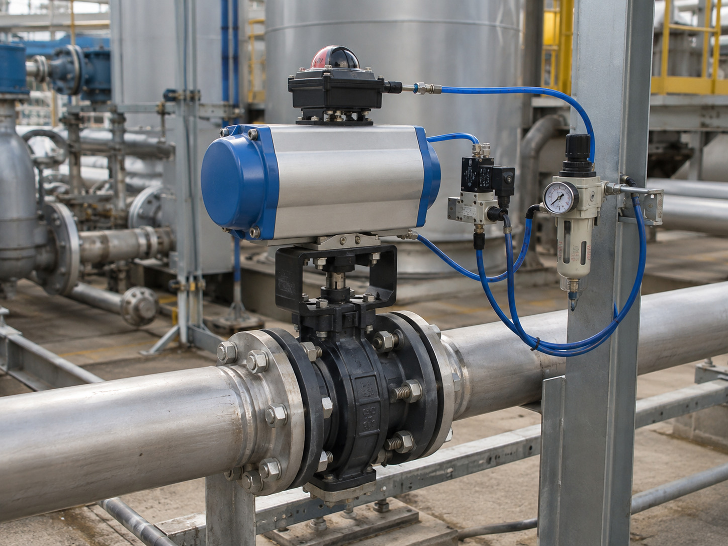
An air operated butterfly valve should be selected as one complete assembly, not as a valve body with a nominally matching actuator. The valve may fit the flanges yet still stall at low plant-air pressure, move the wrong way after a trip, or report a false position to the control system.
The practical solution is to connect every process requirement to the valve, actuator, mounting kit, accessories, and acceptance test that must satisfy it. This guide explains how the assembly works, where selection errors occur, and what engineers and technical buyers should require before approval.
What the Complete Assembly Actually Includes
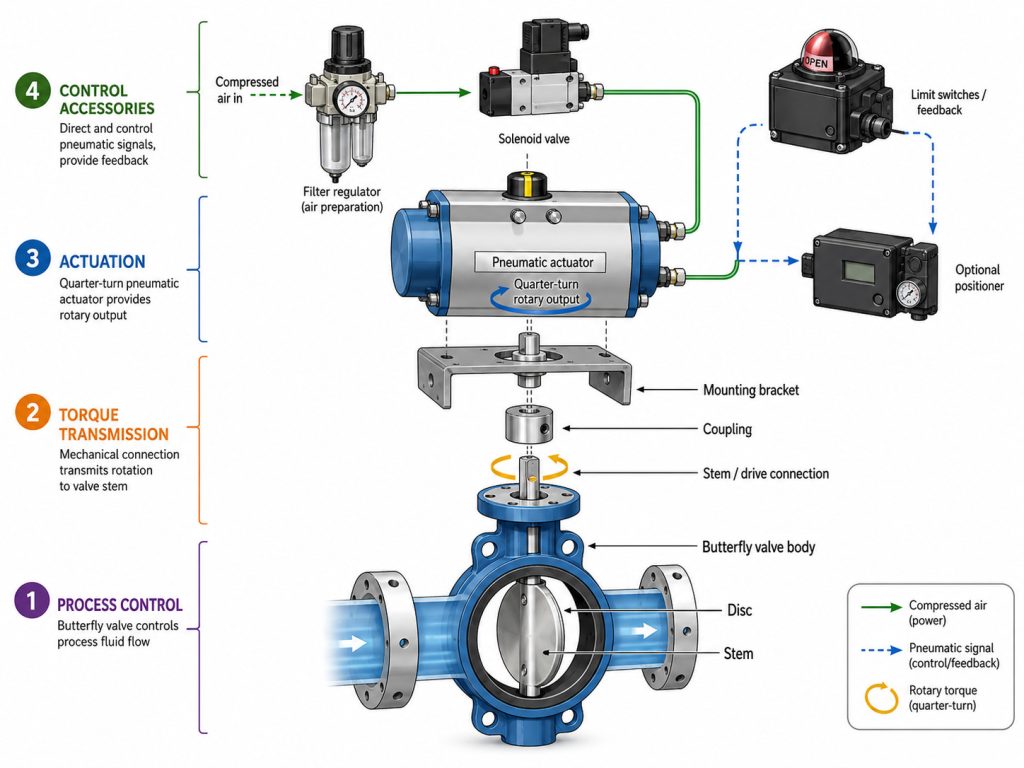
The complete assembly has four functional layers: the valve controls the process fluid, the actuator creates rotary torque, the mounting parts transmit that torque, and the control accessories command and confirm movement. Treating these layers separately creates gaps that often appear only during factory testing or commissioning.
An air-operated butterfly valve is a quarter-turn valve whose disc is rotated by a pneumatic actuator. Compressed air moves pistons or another internal mechanism; a rack-and-pinion or scotch-yoke drive commonly converts that movement into roughly 90 degrees of stem rotation. The disc sits near parallel to the flow when open and across the flow path when closed.
The valve body, disc, stem, seat, and shaft seals determine pressure containment, media compatibility, flow capacity, and shutoff. The actuator determines available torque and motion. The bracket, coupling, and drive connection transfer torque, while the solenoid valve, limit switches, air preparation equipment, and positioner—when required—connect the package to the control system.
Pneumatic operation is a practical fit for automated isolation, sequencing, and moderate control duties in water-treatment filter banks, HVAC water loops, chemical process lines, utilities, and other plants with a dependable instrument-air system. It is especially useful when rapid repeatable motion or a spring-driven safe position is required. It is less attractive at remote sites without reliable compressed air, so the actuation method should follow the available utilities and process consequence rather than a general preference.
Start with Valve Duty Before Selecting the Actuator
The base valve must suit the real process duty before the actuator can be sized correctly. Pipe size alone does not define the required materials, shutoff performance, flow behavior, or operating torque.
Record the media composition, solids or crystallization risk, minimum and maximum temperature, maximum line pressure, maximum differential pressure, normal flow, flow direction, and cycle frequency. Then state whether the valve will isolate, throttle, or perform both duties. For isolation, define the leakage requirement and pressure direction; for modulation, define minimum, normal, and maximum flow with the available pressure drop.
This table shows how the same service input affects both halves of the package.
| Service input | Valve decision it changes | Actuator or control decision it changes |
|---|---|---|
| Media and solids | Body, disc, stem, seat, and internal geometry | Deposit or swelling allowance in the torque basis |
| Pressure and temperature | Rating, seat design, and material limits | Seating, unseating, and running torque |
| Maximum differential pressure | Disc load and shutoff capability | Governing actuator output requirement |
| Isolation or modulation | Leakage target or required Cv curve | Solenoid-only control or positioner-based control |
| Body style and flange standard | Wafer, lug, or flanged construction | Bracket, coupling, access, and disc-clearance checks |
The important sequence is media and duty first, valve construction second, and actuator selection third. A chemically compatible seat can still create a higher torque demand, while a line-size valve that isolates well may be a poor modulating choice if normal operation remains near the seat.
Match Actuator Torque at Minimum Available Air Pressure
The actuator must exceed the valve’s governing torque at every critical point in the stroke and at the lowest guaranteed pressure that actually reaches the actuator. Comparing a catalog torque at nominal shop air with a generic valve torque based only on diameter is not a reliable sizing method.
Ask for the valve’s seating, unseating, running, and dynamic torque basis for the selected size, seat, temperature, differential pressure, flow direction, and media condition. Then compare it with actuator output across the full travel at minimum supply pressure after regulator, tubing, and control-valve losses. For a spring-return unit, verify the air stroke and spring stroke separately because available torque changes as the springs compress or extend.
ISO 5115:2023 applies to a packaged part-turn valve assembly comprising the valve, actuator, and mounting kit when required. Its scope reinforces a useful procurement rule: sizing responsibility belongs to the assembled package. A detailed package-level actuator selection should therefore document the valve torque basis, actuator output at minimum air pressure, direction-specific output, required stroke time, operating frequency, and the reason for any design margin.
Oversizing is not automatically safer. It can increase cost, air consumption, package weight, and the mechanical load applied if stops or alignment are wrong. The goal is adequate documented output under the worst credible condition, not the largest actuator that fits the mounting flange.
Define the Fail Position from the Process Hazard
The safe position must be chosen from the process consequence and then translated into actuator and control logic. “Single acting,” “double acting,” and “fail-safe” are hardware descriptions; they do not by themselves prove what the assembled valve will do during a real loss-of-energy event.
Evaluate at least three separate events:
- Loss of instrument air: Decide whether the valve must close, open, hold for a stated time, or move under another stored-energy source.
- Loss of electrical power: Confirm the de-energized state of the solenoid, positioner, and feedback devices while considering whether air remains available.
- Loss of command signal: Define how the controller or positioner responds to a missing or invalid signal.
A spring-return actuator can provide fail-closed or fail-open movement, but only if its orientation, coupling, solenoid venting state, and spring torque are correct for the valve load. A double-acting actuator does not automatically fail in place: leakage and process torque may allow movement unless a suitable lock-up or reserve-air circuit is engineered and tested.
Write the cause-and-effect statement in testable language. For example: When the solenoid de-energizes, the actuator shall vent and drive the disc closed; the closed limit switch shall confirm the final position to the PLC. Factory acceptance can verify that sentence. “Provide a fail-safe actuator” cannot.
Match Accessories to On-Off or Modulating Duty
The accessory package must provide the required command, air preparation, feedback, and control accuracy for the stated duty. Adding accessories by habit can leave a critical function unproved, while omitting one can make the package impossible to operate or monitor as intended.
For on-off duty, the common functions are:
- A solenoid valve routes or vents instrument air in response to the command.
- Open and closed limit switches provide discrete position confirmation.
- A filter regulator conditions the supply and maintains the specified pressure at the package.
- Tubing, fittings, flow controls, and exhaust devices establish the real air path and stroke time.
For modulating duty, add a positioner that matches the control signal and decide whether independent position feedback is required. The valve must also be sized from its capacity at the expected disc angles, not only from its full-open line-size capacity. Review the butterfly valve flow characteristics so minimum, normal, and maximum flow fall within a usable part of the travel; the ISA75.01 framework covers flow equations used for formal control-valve sizing.
Stroke time is a result of the whole pneumatic circuit. Actuator volume, available pressure, tubing length and bore, solenoid flow capacity, exhaust restriction, speed controls, valve torque, and temperature all affect it. Specify opening and closing time separately and test both on the assembled valve; rapid closing should also be checked against liquid-surge risk.
Confirm Mounting, Coupling, Clearance, and Installation
A shared actuator flange pattern is necessary, but it is not proof that the mechanical assembly will transmit the required torque correctly. Stem geometry, coupling engagement, bracket stiffness, alignment, actuator orientation, and available installation space still need drawing-level confirmation.
ISO 5211:2026 specifies attachment flange dimensions, driving-component dimensions, and reference torque values for part-turn actuator interfaces. Its published scope also places the attachment of the intermediate support to the valve outside the standard. In practice, an ISO-pattern match can coexist with an unsuitable stem square, short coupling engagement, flexible bracket, or incorrect orientation.
Require a general-arrangement drawing that identifies the valve stem, coupling, bracket, actuator model, mounting direction, total height, air ports, accessory access, and maintenance clearance. If the project involves end-of-line isolation or one-sided pipe removal, resolve the lugged versus wafer body decision from the stated dead-end rating rather than from the presence of body lugs alone.
Before tightening the flanges, verify pipe bore, liner, gasket arrangement, and disc clearance. A matching nominal size does not prove that the open disc will clear a thick liner or adjacent fitting. After assembly, set the stops to the valve’s correct open and closed positions; do not use the actuator stop to force a misaligned disc deeper into the seat.
Turn Every Requirement into Acceptance Evidence
A specification is complete only when each critical requirement has an approval record, calculation, or test that proves it. This evidence chain prevents a technically plausible RFQ from becoming an untestable package at the factory.
Use the following matrix to define what must be submitted or witnessed.
| Requirement | Evidence to approve or witness | Decision it closes |
|---|---|---|
| Valve suitability | Data sheet, pressure-temperature rating, material list, and approved drawing | Confirms the valve matches the process and piping |
| Actuator sizing | Valve torque basis and actuator output table at minimum air pressure | Proves adequate output throughout the stroke |
| Fail action | Cause-and-effect statement, solenoid state, orientation, and loss-of-energy test | Confirms the real safe position |
| Mechanical fit | Stem, coupling, bracket, mounting, and disc-clearance drawing | Prevents fit, alignment, and load-transfer errors |
| Shutoff | Named test standard, medium, pressure, direction, duration, and result | Makes the leakage claim measurable |
| Control integration | Switch settings, signal calibration, physical position check, and measured stroke time | Proves command and feedback agree |
| Traceability | Nameplate, serial or lot reference, material records, and release documents | Connects supplied hardware to its records |
The most important evidence is configuration-specific. A general actuator brochure does not prove output at your minimum air pressure, and a generic certificate does not prove the materials or test result of the supplied valve.
RUITO’s published industrial butterfly valve range covers wafer, lug, and flanged configurations from DN25 to DN3000 at PN10, PN16, and PN25, with material-dependent temperature limits and multiple body, disc, and seat materials. The same page lists a material certificate, dimensional inspection report, torque test log, hydrostatic test chart, leakage certificate, and pre-shipment release records among its available quality documents. It also states shell testing at 1.5 times rated pressure and a 6 bar air seat test for soft-seated valves. These are family and process capabilities; the approved data sheet and inspection plan must still state the exact limits and tests for the ordered assembly.
Build an RFQ That Prevents Rework
A usable RFQ describes the process, pneumatic system, control behavior, mechanical interface, and required evidence in one package. It should give the supplier enough information to calculate, select, draw, and test the assembly without relying on assumptions.
Include:
- Media, concentration, solids content, and cleaning or flushing fluids
- Minimum, normal, and maximum pressure and temperature
- Maximum differential pressure in each required flow direction
- Pipe size, flange standard, pipe bore, body style, and face-to-face requirement
- Isolation or modulating duty, flow data, leakage requirement, and shutoff direction
- Cycle frequency, required opening and closing time, and required fail position
- Minimum, normal, and maximum air pressure plus the air-quality requirement
- Solenoid voltage, command signal, feedback signals, and control-system interface
- Ambient conditions, enclosure or hazardous-area requirements, and manual-override need
- Required drawings, calculations, certificates, inspection plan, witness points, and release records
If the piping class calls for API requirements, do not stop at “API 609 compliant.” Use an API 609 purchase specification that identifies the applicable edition and category, body style, pressure and temperature basis, shutoff direction, mating flanges, actuator duty, and test requirements.
At factory acceptance, test the command and feedback as a loop. Command open, confirm the physical disc position and open switch, command closed, confirm the physical position and closed switch, verify the leakage result, and then simulate every specified loss-of-energy event. The package passes only when motion, final position, feedback, timing, and shutoff agree.
Make the Assembly Prove the Decision
A reliable air operated butterfly valve aligns process duty, valve construction, torque at minimum air pressure, fail logic, accessories, mechanical interfaces, and acceptance evidence. If one item is missing, the package still contains an assumption that can surface during commissioning.
When your data is complete, send the specification, drawings, quantity, and inspection requirements. If some parameters are still open, start with the media, pressure, temperature, size range, required action, known air supply, and project stage. The RUITO team can review those inputs and help close the remaining decisions through the project contact page.
Frequently Asked Questions
Does an air operated butterfly valve need electricity?
The actuator itself uses compressed air, but the complete package may still need electricity. Solenoid valves, limit switches, positioners, and control-system interfaces commonly use electrical power, so air loss and power loss must be evaluated as separate events.
Can a manual butterfly valve be retrofitted with an air actuator?
Yes, if the existing valve is suitable for automation and its condition and torque are known. Check the mounting interface, stem dimensions, coupling engagement, bracket load, disc clearance, seat condition, and operating torque before selecting the actuator; a custom bracket cannot correct a worn or binding valve.
Can an air-operated butterfly valve control flow accurately?
It can modulate flow when the valve is correctly sized, its usable Cv curve matches the process range, and a suitable positioner controls the actuator. A line-size valve that operates mainly near closed or nearly full open may provide poor control even when its positioner works correctly.
How should air consumption be specified?
Specify air consumption at the defined supply pressure and cycle rate for the selected actuator and circuit. The calculation should include actuator volume, single- or double-acting operation, expected cycles, solenoid and tubing arrangement, and any reserve-air function rather than using a valve-size estimate.