
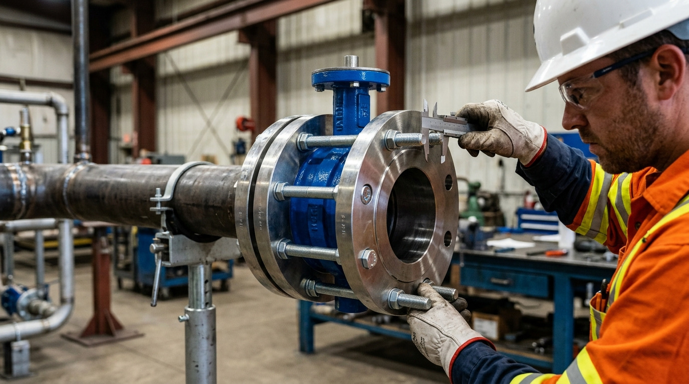
The correct 6 butterfly valve bolt size for an ASME Class 150 connection starts with 3/4-10 UNC fasteners and eight bolt positions per flange face, but bolt length depends on whether the valve is wafer, lug, or double-flanged. Ordering from nominal size alone can leave a wafer bolt too short, make a lug screw bottom in its tapped hole, or produce the wrong seat compression.
This guide separates the standard flange dimensions from the valve-specific checks. It gives engineers, buyers, and installers a practical way to confirm hardware for the butterfly valve configuration actually going into the line.
The Short Answer for a 6-Inch Class 150 Valve
For a 6-inch ASME Class 150 butterfly valve, use a 3/4-inch nominal fastener diameter, commonly called out as 3/4-10 UNC when the thread is specified. The Class 150 flange has eight bolt positions on each face. A wafer body commonly uses eight long through-bolts or studs across the flange-valve-flange assembly, while a lug body commonly uses eight separate fasteners from each side, or 16 for a normal two-flange installation.
Do not turn that answer into a universal length. The flange pattern fixes diameter, count, hole clearance, and bolt circle; the valve drawing and installed joint determine length.
The following table shows which values are a sound starting point and which still need confirmation.
| Item | 6-inch ASME Class 150 starting value | What still needs verification |
|---|---|---|
| Nominal fastener diameter | 3/4 in | Fastener grade, material, coating, and project specification |
| Common UNC thread | 3/4-10 | The tapped lug or drawing must call for this exact thread |
| Bolt positions | 8 per flange face | Wafer, lug, or double-flanged arrangement |
| Flange bolt-hole diameter | 7/8 in | Valve-body clearance and centering features |
| Flange bolt circle | 9-1/2 in | The mating flange standard and pressure class |
| Finished fastener length | Not fixed by NPS 6 alone | Valve series, flange thickness, gaskets, washers, nuts, and engagement |
The practical result is simple: 3/4-10 and eight positions answer the pattern question, not the finished hardware order.
What the 6-Inch Class 150 Pattern Fixes
The flange standard fixes the drilling pattern, while the valve design fixes how the fastener passes through or enters the body. The official ASME B16.5 scope covers dimensions, tolerances, bolting, gaskets, and flange joints through NPS 24; it also expresses bolt and bolt-hole diameters in inch units.
For NPS 6 Class 150 fit-up, the key pattern values are eight 3/4-inch fasteners on a 9-1/2-inch bolt circle, with 7/8-inch flange holes. A detailed Class 150 flange-fit reference helps you check those fixed dimensions before moving to valve-specific length.
Do not use this pattern for every valve marked “6 inch.” Class 300 drilling is different. DN150 PN-rated flanges are not automatically interchangeable with NPS 6 Class 150 flanges. Steel, gray-iron, and thermoplastic mating flanges may also require different length and seating checks even when a field measurement appears close.
Wafer and Lug Bodies Need Different Bolt Arrangements
A 6-inch wafer valve and a 6-inch lug valve can share the same flange pattern but require completely different fastener arrangements. Body style therefore comes before length in any order review.
Wafer body
A wafer valve is clamped between both mating flanges. Its through-bolts or studs must span the two flanges, the valve width along the bolt path, any specified sealing allowance, washers, nuts, and the required thread projection.
The eight positions refer to fasteners crossing the complete assembly. They do not mean eight bolts on each side.
Lug body
A lug valve has tapped body lugs, so each flange is fastened independently. For NPS 6 Class 150, that usually means eight cap screws or tap-end studs per side and 16 for two connected flanges.
The lug butterfly valve bolt chart is only the starting point. Confirm the internal thread, usable thread depth, blind or through-tapped construction, retainer side, and bottoming clearance on the approved drawing.
Double-flanged body
A double-flanged valve creates two separate flange joints. Each side uses the applicable flange pattern, gasket system, and fastener stack-up. Do not use a wafer through-bolt length or a lug cap-screw length for this body style.
If you are still deciding between body styles, review the operational and wafer fit and installation risks before the bolt list is released.
Calculate Length from the Actual Joint Stack-Up
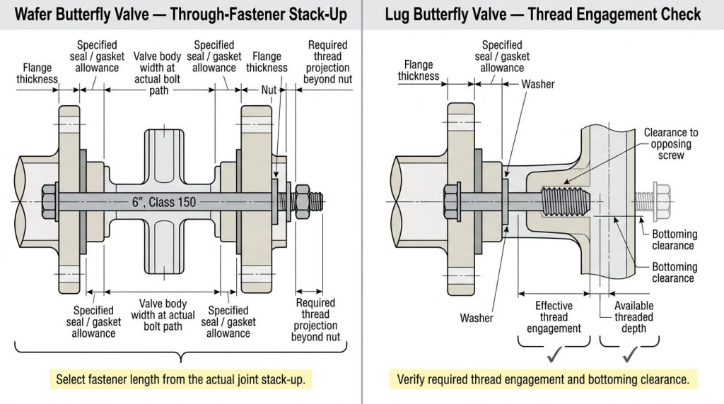
Determine fastener length from the parts that the installed fastener must cross or engage, then verify the result against the valve drawing. A catalog length can be a check value, but it should not replace the physical stack-up.
Wafer through-bolt or stud check
For a wafer assembly, account for:
- both pipe-flange thicknesses;
- the valve-body width at the actual bolt path;
- only the gaskets or seat allowance specified for that valve;
- all required washers;
- nut height; and
- the specified thread projection beyond the fully engaged nut.
Measure at the bolt line, not at the thinnest visible part of the valve body. Also check clearance around the neck, gearbox bracket, actuator support, and casting bosses so the chosen head, nut, and wrench can be used.
Lug cap-screw check
For each side of a lug valve, account for the pipe-flange thickness, specified gasket or seat allowance, washer thickness, and required effective engagement in the lug. Then compare that installed length with the usable tapped depth.
A screw that is too long may bottom in a blind hole or meet the opposing screw in a through-tapped lug before it clamps the flange. A screw that is too short can leave inadequate effective engagement. Either condition can feel tight at the wrench while the joint remains unsafe.
Treat Torque, Gaskets, and Materials as Separate Decisions
Bolt diameter is a fit dimension; it does not by itself determine tightening torque, gasket use, or fastener material. These items must come from the approved valve manual, project bolting specification, and actual joint condition.
Do not derive torque from 3/4-inch diameter alone
The same wrench torque can create different bolt loads when fastener grade, coating, lubrication, thread condition, or washer arrangement changes. The seat or gasket also sets allowable compression. Use the specified staged cross-pattern sequence, but obtain the target torque from the controlled project source rather than a generic internet chart.
Stop the installation if the piping must be pulled into alignment with the bolts, the disc rubs the pipe bore, the liner extrudes unevenly, or a lug screw stops before the flange is seated. Correct the fit-up cause before applying final torque.
Confirm whether a separate gasket belongs in the joint
Many resilient-seated wafer and lug valves use the seat face as the flange seal, while other designs require a separate gasket. Adding an unapproved gasket changes bolt length and seat compression; omitting a required gasket creates a different leakage path. The valve manual and drawing must decide this point.
Fastener material needs the same discipline. Match the grade, coating, corrosion allowance, temperature capability, and any plant compatibility requirement rather than selecting stainless or plated hardware by appearance.
Use This Pre-Order Fit Check
Do not release a 6-inch butterfly valve bolt order until the purchase line identifies the joint well enough for another engineer to reproduce the decision. Record these items:
- NPS 6 or DN150, without treating the two standards as interchangeable.
- Flange standard, material, facing, and rating, such as ASME B16.5 Class 150.
- Valve manufacturer, model or series, body style, and approved drawing revision.
- Eight through-fasteners for a wafer body, eight per side for a lug body, or the defined arrangement for a double-flanged body.
- 3/4-10 UNC only after the thread callout is confirmed where a threaded valve lug is involved.
- Fastener type, grade, material, coating, nuts, washers, and lubrication condition.
- Gasket or integral-seat sealing arrangement.
- Calculated installed length, usable thread engagement, and bottoming or collision clearance.
- Approved tightening procedure and torque source.
Before final tightening, center the valve with the bolts loose, support the piping independently, and verify disc clearance through the required travel. Tighten progressively in a cross pattern, then repeat the clearance and seating checks. A correct bolt list can still fail if field alignment changes the load path.
Get the Bolt Set Right Before Installation
The dependable answer is 3/4-10 UNC with eight Class 150 flange positions for a 6-inch valve, followed by a body-specific length check. Wafer assemblies need a full through-stack calculation; lug assemblies need separate screws on each side plus verified engagement and bottoming clearance.
RUITO can review a valve drawing, flange details, body style, sealing arrangement, and bolt list even when your project data is not yet complete. Send the information you already have through our project contact page so the remaining fit questions can be resolved before installation.
FAQ
Is DN150 the same as a 6-inch butterfly valve bolt pattern?
No. DN150 is the common metric nominal counterpart to NPS 6, but the flange standard and pressure rating control the drilling. An EN PN-rated flange should not be treated as an ASME Class 150 flange without comparing the approved dimensions.
Can I replace a 3/4-10 bolt with an M20 bolt?
Not in a tapped lug unless the drawing explicitly permits it. The diameters may look close, but the thread systems are different and can damage the lug or fail inspection. For a clearance-hole joint, the complete flange and fastener specification still governs substitution.
Does a 6-inch lug butterfly valve use 8 or 16 bolts?
It uses eight fastener positions per flange face and normally 16 separate fasteners for a two-flange installation. A one-sided or dead-end arrangement must follow the valve’s stated pressure and bolting limits.
Do I need separate flange gaskets with a butterfly valve?
Only when the valve manual or project specification calls for them. Many resilient seats seal directly against suitable flange faces, while other valve designs use separate gaskets. Adding or removing a gasket changes the installed stack-up and compression.