
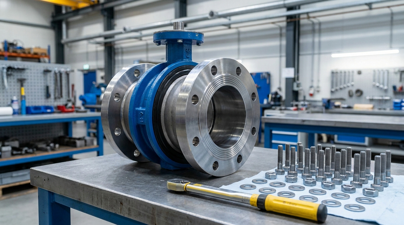
Understanding the butterfly valve bolt chart means knowing how to map nominal pipe sizes and pressure classes to the exact dimensions, quantities, and torque limits of fasteners required to secure a reliable flange connection. You face chronic flange leaks, stripped casing threads, or unexpected downtime when you install valves with improperly selected bolts. A single mismatched cap screw can lead to catastrophic joint failure, exposing your plant to severe safety hazards and expensive emergency shutdowns. By utilizing a precise butterfly valve cap screw chart, you can eliminate the dangerous guesswork and ensure a perfectly aligned, code-compliant seal every single time.
What is a butterfly valve cap screw chart?
A butterfly valve cap screw chart is a comprehensive technical reference table that specifies the precise size, length, thread pitch, and quantity of fasteners required to install a butterfly valve safely into a piping system. This guide ensures that field installers, design engineers, and procurement teams have a shared, exact blueprint for joint assembly. By referencing this document, you can eliminate the dangerous guesswork that leads to loose joints or damaged valve bodies.
Core Purpose of the Diagram
The core purpose is to streamline procurement and field installation while maintaining structural safety compliance across high-pressure systems. When you look up a specific valve size, the chart quickly reveals how many fasteners are needed per flange and their exact dimensional tolerances.
Think about it:
- Provides precise thread metrics
- Specifies fastener counts per flange
- Determines length clearance safety margins
Why Precision is Critical
Precision is vital because even a millimeter deviation in thread depth can jeopardize the seal. You must match the flange standard to prevent localized stress.
What does this mean?
- Prevents flange warping and fatigue
- Reduces localized high-stress spots
- Ensures even pressure on gaskets
| Parameter | Primary Purpose | Standard Source |
|---|---|---|
| Thread Diameter | Fits bolt hole perfectly | ASME B16.5 |
| Grip Length | Clamps without bottoming out | ASTM Fastener Spec |
This comparison shows how dimensional precision impacts the overall joint integrity.
Key Takeaway: Using the chart ensures you buy and install perfectly matched components, eliminating field assembly errors and structural weak points.
Why use a butterfly valve cap screw chart?
You use a butterfly valve cap screw chart to prevent catastrophic structural joint failures, ensure uniform gasket compression, and protect expensive piping assets from uneven stress. Operating without standard bolt guidelines risks shearing fasteners, leaking hazardous chemicals, or cracking ductile iron valve casings under thermal expansion. By relying on a precise butterfly valve cap screw chart, you align your field protocols with proven mechanical engineering standards.
Avoiding Fastener Failures
When high pressure passes through your pipeline, the fasteners bear massive mechanical loads. If you use bolts with insufficient yield strength, the joint will separate under sudden pressure transients.
But that is not all.
- Ensures safety under hydraulic surges
- Reduces bolt fatigue over thermal cycles
- Guarantees uniform load sharing
Protecting Valve Bodies
Uneven clamping forces can permanently distort the valve seat, making shutoff impossible. By tracking standardized dimensions, you keep the rotating disc perfectly aligned with the sealing surfaces.
Here is the catch:
- Maintains tight-shutoff capabilities
- Prevents binding of the valve disc
- Extends elastomeric seal lifetime
| Risk Category | Improper Bolt Use | Correct Bolt Protocol |
|---|---|---|
| Mechanical Failure | Bolt shear and joint rupture | Stable high-pressure hold |
| Valve Operation | Disc binding and seat wear | Smooth rotational clearance |
These comparative outcomes illustrate how proper fastener selection acts as a safeguard for active control equipment.
Key Takeaway: Relying on a verified bolt reference helps you protect your capital investment in valves and maintain long-term piping safety.
How does a butterfly valve cap screw chart align flanges?
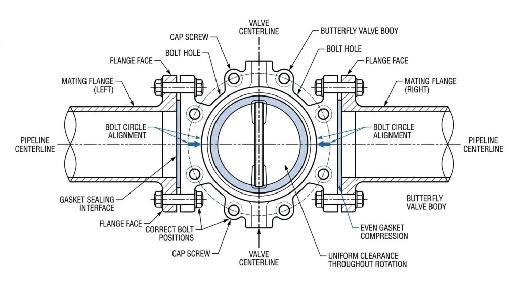
A butterfly valve cap screw chart aligns flanges by mapping the precise spacing, diameters, and quantities of bolts required to match the pre-drilled geometry of different flange standards like ASME B16.5 and EN 1092-1. This ensures that the valve body sits perfectly concentric within the pipeline, allowing the internal disc to rotate without hitting the pipe walls. Proper spatial alignment is the only way to avoid uneven sealing pressure on gaskets and flange faces.
Bridging Global Standards
Industrial pipelines are built using various global standards that do not naturally cross over. If you mix up metric and imperial bolt patterns, you will face severe misalignment during installation.
What does this mean?
- Matches ANSI/ASME bolt circles
- Secures ISO/EN metric compatibility
- Prevents thread stripping in lugs
Resolving Concentricity Issues
A concentric layout prevents the valve disc from scraping against the inner pipe wall. When you align your flanges correctly, you secure high flow efficiency and prevent seat damage.
Think about it:
- Maintains steady fluid dynamics
- Eliminates localized turbulent flow
- Guarantees zero-leak seating
| Standard Type | Measurement Basis | Typical Bolt Circle |
|---|---|---|
| ASME B16.5 | Imperial (inches) | Standard ANSI patterns |
| EN 1092-1 | Metric (millimeters) | Nominal Pressure (PN) patterns |
The data outlines how standard-specific metrics govern the geometric alignment of mating faces.
Key Takeaway: Verifying your flange standards against the chart ensures you achieve flawless concentricity and peak hydraulic efficiency.
What sizes are in a butterfly valve cap screw chart?
A butterfly valve cap screw chart details standard pipe sizes from DN15 to DN600 and lists corresponding bolt diameters, lengths, and thread pitches for each Class rating. These sizes are meticulously calculated to handle the increased hydrostatic loads associated with larger pipe diameters. Using the chart ensures you never install a fastener that is too small to handle the pipeline’s operational forces.
Thread Diameters and Pitches
The thread diameter and pitch determine how much tension a bolt can hold. You must match these dimensions precisely to prevent thread stripping under load.
Here is the catch:
- Specifies UNC threads for imperial
- Defines metric pitches for EN flanges
- Ensures secure thread-lug engagement
Determining Grip Lengths
Grip length refers to the distance that clamps the joint together before thread engagement begins. If your bolts are too short, they will strip out; if they are too long, they will bottom out.
But that is not all.
- Accounts for flange thickness
- Includes double gasket clearances
- Secures full heavy hex nut engagement
| Nominal Size | Bolt Diameter | Bolt Quantity (Class 150) |
|---|---|---|
| 2-Inch (DN50) | 5/8″ | 4 Fasteners |
| 8-Inch (DN200) | 3/4″ | 8 Fasteners |
This size progression demonstrates how mechanical dimensions scale up to handle expanding hydraulic forces.
Key Takeaway: Selecting the precise size from the chart guarantees that you have enough mechanical load-bearing capacity for your specific pipe diameter.
Does a butterfly valve cap screw chart detail materials?
A butterfly valve cap screw chart specifies suitable material grades, such as high-tensile carbon steel (ASTM A193 B7) and corrosion-resistant stainless steel (ASTM A193 B8M), to match specific process environments. Selecting the wrong material can lead to rapid oxidation, premature structural fatigue, or mechanical galling. By verifying material compatibility with the chart, you ensure the joint withstands operational temperatures, chemical corrosion, and high pressures.
Carbon Steel for High Strength
High-pressure and high-temperature systems often require the superior tensile strength of carbon steel. You will find that these materials hold higher preloads without stretching.
Think about it:
- Excellent for steam lines
- Withstands high-pressure loads
- Often features protective zinc plating
Stainless Steel for Corrosion Control
If you operate in marine, chemical, or outdoor environments, stainless steel is your best defense against rust. However, you must manage thread galling during installation.
What does this mean?
- Grade 316 resists chemical attack
- Maintains integrity in humid climates
- Requires anti-seize lubrication
| Material Grade | Tensile Strength | Primary Environment |
|---|---|---|
| ASTM A193 B7 | Extreme | High pressure/temperature steam |
| ASTM A193 B8M | High | Corrosive chemical/marine process |
This material comparison guides you in matching the bolt metallurgy to the specific fluid media.
Key Takeaway: Using the correct material grade ensures you avoid mechanical degradation, joint relaxation, and hazardous piping failures over time.
Who needs a butterfly valve cap screw chart in a plant?
In any industrial plant, a butterfly valve cap screw chart is an indispensable reference for design engineers, procurement specialists, field maintenance technicians, and quality assurance inspectors. Each department relies on this document to maintain consistency, accuracy, and compliance from the initial system design to physical assembly. Without this shared technical standard, communication gaps can lead to purchasing errors and unsafe field installations.
Engineering and Procurement Teams
Design engineers need precise fastener dimensions to map clearance envelopes and avoid interference during construction. Procurement teams reference the same data to build accurate bills of materials.
Here is the catch:
- Eliminates incorrect hardware purchases
- Speeds up project engineering phases
- Maintains tight project cost controls
On-Site Maintenance Crews
Technicians on the plant floor use the chart daily during valve replacements to verify that existing bolts match original specifications. This keeps your operating systems secure and compliant.
But that is not all.
- Speeds up emergency plant repairs
- Ensures consistent safety inspections
- Reduces reliance on hazardous guesswork
| Plant Role | Primary Document Application | Main Operational Benefit |
|---|---|---|
| Design Engineer | Clearance and load modeling | Clash-free, compliant piping designs |
| Field Technician | Direct installation and torque | Safe, leak-free flange seals |
The role-based breakdown demonstrates how a single chart unites different departments around a unified safety standard.
Key Takeaway: Integrating this technical reference into your team’s workflow ensures you minimize human error across all stages of project execution.
Where is a butterfly valve cap screw chart applied?
A butterfly valve cap screw chart is applied across diverse industrial fluid handling systems, including oil and gas refining, chemical processing, municipal water treatment, and marine piping networks. Each of these applications features unique environmental and operational challenges that demand specific fastener configurations. By applying the chart to your industry-specific setup, you guarantee that your high-pressure and corrosive fluid lines remain structurally sound.
Process Industry Environments
Refineries and chemical plants handle highly volatile and aggressive media under strict safety regulations. You must apply the precise bolt parameters to meet emission-control laws.
What does this mean?
- Controls fugitive process emissions
- Meets strict environmental standards
- Handles cyclic thermal operations
Municipal and Offshore Facilities
In water treatment and marine settings, moisture and salinity are constant threats to structural joints. You rely on the chart to select corrosion-resistant combinations.
Think about it:
- Resists salt spray in marine environments
- Secures large-diameter municipal water mains
- Reduces long-term corrosion failures
| Industry | Main Challenge | Fastener Strategy |
|---|---|---|
| Oil & Gas | High pressure/temperature | Alloy steel with protective coatings |
| Water Treatment | Continuous moisture/humidity | Stainless steel or galvanized bolts |
This application matrix highlights how environmental conditions dictate the chosen fastening strategy.
Key Takeaway: Applying the correct chart specifications ensures you maintain environmental compliance and joint integrity in any operational setting.
Can a butterfly valve cap screw chart prevent leaks?
Yes, a butterfly valve cap screw chart directly prevents leaks by specifying the correct torque values and bolting patterns needed to compress gaskets evenly without distorting the valve seat. Uneven gasket stress is the root cause of minor leak paths that eventually grow into full joint blowouts under pressure. Using the chart keeps your operations safe by enforcing uniform mechanical loading across the entire sealing face.
Eliminating Gasket Sealing Errors
If your bolts are tightened unevenly, the gasket will be crushed in some areas and loose in others. This uneven compression creates microscopic paths for fluids to escape.
But that is not all.
- Locks in consistent clamping force
- Ensures even pressure on elastomeric seats
- Prevents localized gasket failure
Controlling Joint Relaxation Over Time
Under operational vibrations and pressure spikes, bolts can experience relaxation over time. The chart provides the initial tension needed to resist these dynamic forces.
Here is the catch:
- Reduces regular re-torquing intervals
- Counteracts pipe vibration effects
- Maintains a long-term reliable seal
| Assembly Quality | Gasket Load Distribution | System Leak Risk |
|---|---|---|
| Code-Compliant | Completely uniform across face | Negligible / Zero |
| Guessed Assembly | Uneven, localized high-stress | Highly probable over time |
This performance comparison shows the direct relationship between uniform bolt load and leak prevention.
Key Takeaway: Adhering to the chart’s torque and sequence instructions ensures you eliminate leak paths and protect your system from costly shutdowns.
How to read a butterfly valve cap screw chart?
Reading a butterfly valve cap screw chart requires you to first identify your valve’s body configuration (wafer or lug), confirm the mating flange standard, and locate your specific nominal size and pressure class. Once you find the correct intersection point on the grid, you can quickly read off the required bolt dimensions and torque limits. Following this step-by-step reading method prevents you from mixing up incompatible sizes or styles during installation.
Step-by-Step Parameter Lookup
Start by checking the nameplate on your valve to confirm the Nominal Pipe Size (NPS) and pressure rating (such as Class 150). You then cross-reference these values on the chart axes.
What does this mean?
- Finds size in NPS or DN
- Verifies ASME vs. EN classifications
- Prevents mixing mismatched standards
Implementing Torque Recommendations
The final step of reading the chart is extracting the recommended torque limits and applying them in a cross-tightening pattern. This star sequence ensures that the flange draws together perfectly square.
Think about it:
- Prevents bending of the valve shaft
- Ensures uniform gasket seating
- Protects brittle cast iron casings
| Reading Step | Technical Goal | Direct Field Action |
|---|---|---|
| 1. Find NPS & Class | Identify baseline geometry | Locate target row on the chart |
| 2. Extract Torque | Define mechanical limits | Set calibrated torque wrench |
These progressive steps turn raw chart data into safe, repeatable field actions.
Key Takeaway: Mastering the chart reading process ensures you install fasteners with extreme precision, avoiding costly alignment mistakes on-site.
Is a butterfly valve cap screw chart standardized?
Yes, a butterfly valve cap screw chart is standardized according to recognized international organizations like ASME, API, and ISO to ensure total compatibility across global supply chains. These standards define the dimensions, threads, and material classes of fasteners, ensuring that a valve manufactured in one country fits perfectly into a piping system built in another. By relying on these standardized tables, you maintain strict compliance with global safety and quality regulations.
Alignment with ASME and API
The most common standards used in heavy industry are ASME B16.5 for flanges and API 609 for butterfly valves. These codes dictate the exact dimensions you find in the standard tables.
But that is not all.
- Guarantees physical bolt-hole alignment
- Meets severe industrial safety codes
- Simplifies international parts procurement
Enforcing Global Interchangeability
Standardized specifications allow plants to buy valves and fasteners from different suppliers without compatibility worries. You can trust that the parts will fit together perfectly in the field.
Here is the catch:
- Eliminates single-vendor procurement lock
- Lowers warehousing and inventory costs
- Enforces global quality consistency
| Governing Body | Primary Standard | Focus Area |
|---|---|---|
| ASME | B16.5 / B16.47 | Flange dimensions and drilling |
| API | 609 Specification | Butterfly valve design limits |
This regulatory overview highlights how international standards ensure global hardware compatibility.
Key Takeaway: Using standardized charts ensures your plant remains code-compliant, making future upgrades and maintenance straightforward.
Securing Your Piping Systems Safely
By understanding and implementing the technical parameters detailed in standard bolt charts, you solve the chronic challenges of flange leaks, thread damage, and costly unexpected plant shutdowns. We are committed to supplying high-reliability, code-compliant industrial valves and technical guidance that keep your fluid networks running at peak efficiency. Our expert team stands ready to review your process data, mechanical dimensions, and system specifications to recommend the ideal valve configurations and fastening hardware for your unique plant setups.
Whether you are managing corrosive chemicals, high-temperature steam lines, or large-scale water treatment networks, our vision is to deliver safety and precision to every joint. We invite you to partner with a trusted manufacturer that prioritizes long-term operational integrity and environmental compliance. To get a custom engineering review or to discuss your upcoming project requirements, contact us today and let us help you build a safer, more reliable piping network.
Frequently Asked Questions About Valve Fasteners
Can I reuse old bolts during a new butterfly valve installation?
No, you should never reuse old bolts during a critical valve installation. Over time, fasteners suffer from microscopic thread fatigue, corrosion, and permanent tensile stretching. Reinstalling them under high operational loads increases the risk of joint relaxation, leading to sudden leaks or structural shearing.
What’s the best way to prevent thread galling on stainless steel fasteners?
The best way is to apply a high-quality nickel-based anti-seize lubricant before assembly. This protective coating drastically reduces friction between the mating threads of the bolt and the lug. By lowering friction, you eliminate the localized heat buildup and molecular welding that causes stainless steel threads to bind.
How do I know if my bolts are tightened to the correct torque value?
You know by measuring the tension directly with a recently calibrated torque wrench. Relying on hand-tightening or guessing the tension often leads to uneven compression of the gasket face. By utilizing a calibrated tool, you ensure that every fastener receives the exact mechanical load specified in the technical chart.
How do I know which flange standard is compatible with my system?
You can determine this by checking the dimensional markings stamped on your flange rim or the valve body casing. Cross-referencing these physical markings with standard engineering tables will verify whether your system uses ASME, DIN, or JIS geometries. This step is crucial because even minor pitch differences can cause severe thread damage.