
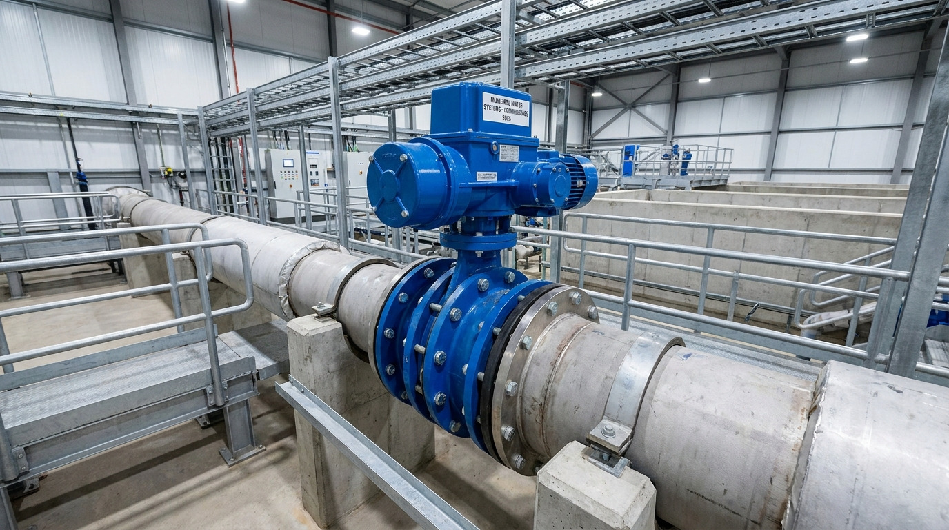
AWWA butterfly valves should be installed with verified flow direction, shaft orientation, disc clearance, alignment, and controlled operating speed. A typical crew may position a large valve correctly between flanges yet face excessive torque, leakage, or disc flutter during startup. These failures delay commissioning and can damage seats, bearings, shafts, or actuators. The following butterfly valve installation guidelines give you a practical method for preventing those problems across municipal and industrial water systems.
What Do Butterfly Valve Installation Guidelines Require?
Butterfly valve installation guidelines require you to match valve design, pipeline geometry, flow conditions, and actuator capability before installation. Confirming these factors during engineering review reduces costly field corrections.
Which Documents Should You Review?
Check approved drawings against delivered equipment rather than relying only on purchase descriptions. Here is the practical starting point: gather every document affecting fit, operation, and acceptance.
- Certified valve and actuator drawings
- AWWA C504 compliance documents
- Flange, gasket, and fastener specifications
- Seat, disc, shaft, and coating data
- Pressure-test and operating procedures
What Should the Preinstallation Check Cover?
Inspect shipping damage, flange protectors, disc position, coating, and actuator stops before lifting. Confirm that pipe supports carry pipeline loads without transferring them through the valve body.
| Check | Acceptable Condition | Field Action |
|---|---|---|
| Disc | Slightly open within body | Protect edges |
| Flanges | Parallel and aligned | Correct piping |
| Actuator | Correct torque and travel | Verify settings |
This comparison identifies conditions that should be corrected before bolting begins.
Key Takeaway: A controlled document and equipment review helps you prevent mismatched flanges, damaged sealing surfaces, and undersized actuators.
How Should Flow Direction Be Selected?
Butterfly valve installation guidelines call for flow direction to follow valve geometry, actuator sizing, and specified shutoff conditions. Offset-disc designs can react differently when flow approaches the flat or domed side.
Why Does Disc Geometry Affect Torque?
Fluid acting on an asymmetric disc creates dynamic torque that changes with disc angle and flow direction. This detail carries real weight: torque toward one side may exceed torque from the opposite direction by more than two times.
- Identify seat, non-seat, flat, and domed sides
- Mark normal and reverse-flow conditions
- Check torque across operating angles
- Confirm actuator margin with actual differential pressure
Which Direction Fits the Operating Case?
Use certified torque and flow data because one universal orientation cannot cover every disc profile. Bidirectional shutoff capability also does not mean both directions produce equal torque or flow capacity.
| Operating Need | Review Point | Possible Effect |
|---|---|---|
| Low torque | Disc-side orientation | Smaller torque demand |
| High test pressure | Seat loading direction | Stronger sealing |
| Low head loss | Published Cv data | Higher capacity |
The preferred direction follows documented performance rather than a visual guess.
Key Takeaway: Correct flow orientation protects actuator capacity while supporting stable operation and dependable shutoff.
How Can Upstream Disturbances Be Controlled?
Butterfly valve installation guidelines control upstream disturbances through straight pipe, suitable shaft orientation, and verified actuator margin. Pumps, elbows, tees, and nearby valves can create uneven velocity across the disc.
How Much Straight Pipe Should You Provide?
Provide six to eight unobstructed pipe diameters upstream when project space permits and supplier data supports that arrangement. When space tightens, pay attention: closer equipment demands a hydraulic and mechanical review.
- Record every nearby elbow, pump, tee, and valve
- Measure straight-pipe distance in pipe diameters
- Identify high-velocity regions
- Review actuator torque under disturbed flow
What If Space Restricts Valve Placement?
Orient the shaft so it divides an uneven velocity profile across both halves of the disc. This arrangement may reduce unbalanced loading although it cannot remove strong turbulence from a close pump discharge.
| Disturbance | Main Risk | Response |
|---|---|---|
| Elbow | Uneven velocity | Reorient shaft |
| Pump discharge | Turbulence and flutter | Add separation |
| Upstream valve | Distorted flow | Review torque |
These responses help your team rank placement changes by probable mechanical impact.
Key Takeaway: Managing disturbed flow reduces disc flutter, actuator overload, bearing wear, and unexpected head loss.
Which Valve Shaft Orientation Works Best?
Butterfly valve installation guidelines generally favor a horizontal shaft for large valves unless upstream flow conditions justify another position. Horizontal mounting reduces debris entry into lower bearing clearances.
Why Can a Vertical Shaft Cause Wear?
Fines, scale, construction debris, and biological material may settle around a lower trunnion bearing. The hidden issue appears later: contamination raises friction and shortens bearing life after commissioning.
- Review suspended-solids content
- Remove construction debris through flushing
- Protect open piping during storage
- Confirm bearing seals and access points
When Should Hydraulic Torque Be Reviewed?
Review hydrostatic torque when a horizontal-shaft valve holds water upstream while downstream piping remains empty. Disc weight and hydraulic head can either assist or resist actuator movement.
| Condition | Torque Influence | Required Check |
|---|---|---|
| Full pipeline | Normal operating load | Dynamic torque |
| Empty downstream | Uneven hydraulic load | Hydrostatic torque |
| Buried service | Access constraint | Gear orientation |
This matrix connects shaft position with actuator and access decisions.
Key Takeaway: A horizontal shaft often protects bearings, but actuator calculations must still include unusual hydraulic loading.
Which Disc Closure Direction Clears Debris?
Butterfly valve installation guidelines should direct the lower disc edge through a self-flushing closing path where solids may settle. Local velocity near that edge can sweep sediment away from sealing surfaces.
How Does Closure Direction Affect Cleaning?
Disc rotation changes fluid velocity along the lower seat during the closing stroke. A small orientation choice can prevent a large repair: suitable rotation helps move grit before full seating.
- Identify expected sediment location
- Confirm actuator rotation before wiring
- Check open and closed position indicators
- Observe disc travel during dry commissioning
What Damage Can Poor Rotation Cause?
Trapped material can cut an elastomer seat, score a disc edge, or prevent full shutoff. Never reverse actuator rotation without checking stop settings, torque switches, and position feedback.
| Observation | Likely Cause | Corrective Action |
|---|---|---|
| Bottom-seat leakage | Trapped debris | Flush and inspect |
| Rising closing torque | Seat obstruction | Stop operation |
| Incorrect indication | Reversed setup | Recalibrate controls |
These symptoms help you separate debris problems from actuator faults.
Key Takeaway: Verified closure direction supports self-cleaning action and lowers the risk of damaged seats or incomplete shutoff.
How Much Disc Swing Clearance Is Needed?
Butterfly valve installation guidelines require clearance based on the certified disc envelope rather than nominal valve size alone. Many short-body discs extend beyond body faces when fully open.
Where Can Disc Interference Occur?
Interference may develop at pipe flanges, reducers, check valves, linings, or nearby instruments. Do not miss this measurement: an assembled joint can hide contact until powered operation bends a shaft or damages a disc.
- Obtain full-open disc dimensions
- Check flange and gasket inside diameters
- Measure nearby pipe obstructions
- Account for thick linings and reducers
How Should Clearance Be Confirmed?
Compare supplier drawings with an as-built pipe survey and rotate the disc slowly before pressure testing. Never force movement when contact, scraping, or sudden torque appears.
| Interface | Verification | Acceptance |
|---|---|---|
| Mating flange | Bore measurement | No disc contact |
| Gasket | Inside diameter | Outside sweep |
| Reducer | Axial distance | Drawing clearance |
The tightest interface determines whether piping geometry needs correction.
Key Takeaway: Verified swing clearance prevents hidden interference from damaging the disc, shaft, seat, or actuator.
Where Should Chemical Injection Points Be Located?
Butterfly valve installation guidelines place chemical injection far enough away for dissolution and dilution before fluid reaches the valve. Concentrated solids or chemicals can attack seats and increase bearing friction.
Why Does Mixing Distance Matter?
Undissolved powder behaves like abrasive grit between moving and stationary surfaces. Here is what operators may overlook: high local concentration can harm elastomers even when average system chemistry appears acceptable.
- Identify every solid and liquid injection point
- Record mixing and dissolution requirements
- Review seat compatibility with concentrated chemicals
- Provide sampling access near the valve
Which Seat Risks Need Review?
Chlorine or chloramine concentration may degrade some nitrile compounds while petroleum-based media can damage EPDM. Confirm compatibility using temperature, concentration, exposure time, and actual seat formulation.
| Exposure | Possible Risk | Design Response |
|---|---|---|
| Powdered chemical | Friction or lockup | Add mixing distance |
| Concentrated oxidant | Elastomer attack | Review compound |
| Oil-based media | EPDM degradation | Select suitable seat |
This screening table flags combinations that need supplier confirmation.
Key Takeaway: Adequate mixing distance protects seats and bearings from chemical attack, abrasion, and unexpected operating torque.
How Can Fluid Hammer Be Limited?
Butterfly valve installation guidelines limit fluid hammer through controlled filling, air removal, pipe support, and calculated valve stroking time. Rapid quarter-turn movement can create damaging pressure waves in long pipelines.
What Events Can Create a Pressure Surge?
Pump trips, trapped air, rapid closure, sudden opening, and moving pipework can generate severe transients. The warning sign may arrive too late: a single bang can precede joint leakage or equipment damage.
- Model pump start and trip cases
- Calculate minimum opening and closing times
- Provide controlled air-release points
- Check pipe anchors and supports
How Should Actuator Speed Be Set?
Set pneumatic, hydraulic, or electric controls from a transient analysis rather than choosing the fastest available stroke. Manual gear operators may also need many turns to keep closure within a safe time.
| Control Method | Speed Device | Verification |
|---|---|---|
| Electric | Programmable travel time | Timed stroke |
| Pneumatic | Flow control valve | Stable pressure |
| Hydraulic | Metering control | Controlled motion |
Measured stroke time should match the hydraulic study under real power conditions.
Key Takeaway: Controlled valve travel protects pumps, piping, joints, and valves from avoidable pressure surges.
How Should the Valve Be Installed and Started?
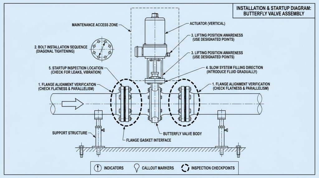
Butterfly valve installation guidelines require aligned flanges, correct lifting, even bolt loading, slow system filling, and monitored startup. The valve body must never serve as a tool for pulling misaligned piping together.
What Installation Sequence Reduces Leakage?
Keep flange protectors installed until the valve reaches its prepared installation area. Once lifting starts, control every interface: use approved lifting points and center the valve without damaging its seat or actuator.
- Clean valve and pipe sealing faces
- Fit compatible gaskets
- Center valve between parallel flanges
- Tighten bolts in a crisscross pattern
- Apply specified and uniform torque
What Should Startup Testing Include?
Fill the system slowly while venting trapped air then inspect body joints, flange gaskets, packing, and seat performance. If packing leaks, follow supplied adjustment limits or cycle a nonadjustable design three to five times.
| Startup Step | Observation | Response |
|---|---|---|
| Slow filling | Pipe movement | Stop and support |
| Pressure hold | External leakage | Correct joint |
| Valve cycling | Abnormal torque | Inspect alignment |
This sequence helps isolate installation faults before routine operation begins.
Key Takeaway: Controlled installation and startup produce reliable sealing without overstressing the valve body, packing, or pipeline.
What Maintenance Records Support Reliable Service?
Butterfly valve installation guidelines depend on traceable maintenance records covering leakage, torque, position, operating time, and process conditions. Trend data gives you earlier warning than occasional visual inspection.
Which Conditions Should Operators Track?
Record baseline values during acceptance then compare them with readings after operating events or scheduled inspections. The pattern tells the story: gradual torque growth may point toward bearing contamination, seat wear, or chemical buildup.
- Opening and closing travel time
- Actuator current, pressure, or torque
- Packing and seat leakage
- Vibration, noise, and disc stability
- Water chemistry and suspended solids
When Does a Change Require Investigation?
Investigate repeated leakage, rising torque, unstable position, abnormal noise, or slower travel. Compare findings with commissioning data before adjusting stops or tightening packing.
| Trend | Possible Cause | Inspection Focus |
|---|---|---|
| Higher torque | Friction or debris | Bearings and seat |
| Longer stroke | Actuator weakness | Power and controls |
| New leakage | Wear or misalignment | Seal interfaces |
Trend direction often provides more value than one isolated measurement.
Key Takeaway: Consistent records help you plan maintenance early while avoiding unnecessary adjustments that could create new damage.
Ready for a More Reliable Valve Installation?
Reliable AWWA butterfly valve performance starts with disciplined engineering and continues through alignment, controlled stroking, chemical review, startup testing, and documented maintenance. These practices address torque, turbulence, debris, clearance, leakage, and pressure-surge risks across a valve’s working life.
For application review, certified drawings, material guidance, or a project-specific valve package, contact us today. We believe dependable flow control begins with verifiable engineering decisions, not field improvisation.
Frequently Asked Questions
Can I install an AWWA butterfly valve in either flow direction?
Yes, if its certified design supports bidirectional service. You should still check how flow direction affects dynamic torque, actuator sizing, seat loading, and full-open capacity.
What’s the best shaft position for a large butterfly valve?
A horizontal shaft usually works best where severe upstream disturbances are absent. This position reduces debris settlement in lower bearing clearances and often simplifies buried gearbox access.
How do I know if the disc has enough swing clearance?
Compare the certified disc envelope with actual flange bores, gaskets, linings, reducers, and nearby equipment. A slow manual rotation before pressurization can reveal hidden interference.
Can I place a butterfly valve beside a chemical injection point?
Usually no, unless mixing calculations and material data confirm safe exposure. Undissolved solids can raise friction while concentrated chemicals may degrade elastomer seats.
What’s the best way to prevent water hammer during startup?
Controlled filling and calculated valve travel provide the best protection. Vent trapped air, verify supports, and set actuator speed from system transient conditions rather than convenience.