
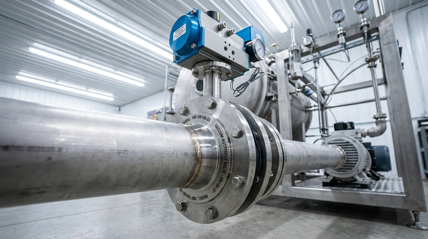
A vacuum butterfly valve isolates or regulates air and clean, noncorrosive gas in vacuum pumping lines through a compact quarter-turn disc. Suppose your pump reaches its target pressure slowly after every cycle. A poorly matched valve may restrict conductance, leak across its seat, or respond too slowly for automated production. The right valve configuration gives you fast isolation, low flow resistance, dependable sealing, and control feedback matched with your process.
That remedy starts with duty conditions rather than nominal diameter alone. You need a clear view of working pressure, acceptable leakage, medium, temperature, cycling rate, mounting space, and actuator logic. This guide turns those variables into practical selection, installation, and maintenance decisions for engineers, EPC teams, and industrial buyers.
Where Does a Vacuum Butterfly Valve Fit Best?
A vacuum butterfly valve fits best in pumping manifolds, chamber isolation points, forelines, and clean gas-routing systems needing rapid quarter-turn operation. Its short face-to-face length suits compact skids while its open disc position supports strong conductance. You can use it for isolation or limited regulation when process stability permits.
Which Applications Gain the Most Value?
Here’s the practical angle: choose this valve where space, cycle speed, and a clear gas path matter more than ultra-fine metering. Manual units suit local service points while powered units support repetitive production cycles.
- Vacuum chambers and evacuation manifolds
- Pump inlet or backing lines
- Clean, noncorrosive gas routing
- Load-lock and test-system isolation
| Application | Main Duty | Selection Focus |
|---|---|---|
| Pumping line | Isolation | Conductance |
| Chamber port | Fast shutoff | Leakage |
| Gas branch | Regulation | Position control |
This comparison links each location with its dominant buying criterion. Key Takeaway: You can narrow suitable configurations quickly by defining whether each node needs isolation, regulation, or both.
What Operating Ranges Define Suitable Vacuum Service?
A vacuum butterfly valve must match working pressure, permissible leakage, temperature, and medium across every process state. Published ranges should cover pump-down, steady operation, venting, and shutdown rather than one nominal point. You should also check whether pressure can reverse across a closed disc.
Which Data Belongs on Your Specification?
Operating pressure may span atmospheric conditions down through high-vacuum duties depending on seal design and construction. Now for the catch: a wide catalog range cannot compensate for an incompatible elastomer or an unverified leak-rate limit.
- Maximum and minimum absolute pressure
- Allowable seat and external leakage
- Process and ambient temperatures
- Gas composition and contamination level
| Parameter | Question for Supplier | Risk if Missed |
|---|---|---|
| Pressure | Full operating span? | Slow pump-down |
| Leakage | Tested limit? | Unstable vacuum |
| Temperature | Seal rating? | Early hardening |
These fields convert a broad product description into a testable purchase specification. Key Takeaway: You gain fewer commissioning surprises when every operating extreme appears on drawings, datasheets, and inspection records.
How Does a Vacuum Butterfly Valve Control Gas Flow?
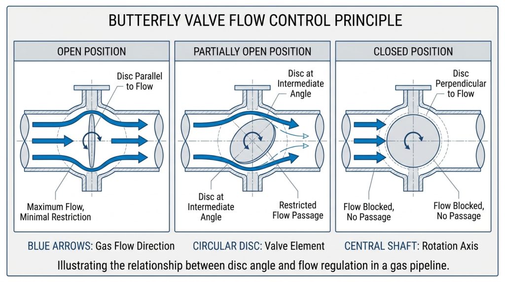
A vacuum butterfly valve controls gas flow as its shaft rotates a circular disc through roughly 90 degrees. A fully open disc leaves a relatively direct path while intermediate angles create changing restriction. You should treat angle and delivered flow as a nonlinear relationship influenced by system pressure losses.
Why Does Disc Position Matter?
Near closed position, a small angular movement can sharply change effective area and control response. This is where things get specific: conductance depends on disc geometry, bore size, piping, and pressure regime rather than angle alone.
- Open for maximum evacuation conductance
- Closed for chamber or pump isolation
- Partly open for coarse flow regulation
- Feedback-equipped for repeatable positioning
| Disc State | Flow Effect | Typical Use |
|---|---|---|
| Open | Lowest restriction | Pump-down |
| Partial | Variable restriction | Regulation |
| Closed | Flow cutoff | Isolation |
The pattern shows why position feedback matters during repeatable process control. Key Takeaway: You can avoid unstable regulation by sizing against installed conductance and expected control range rather than valve diameter alone.
Which Actuator Suits Each Operating Duty?
A vacuum butterfly valve should use manual operation for occasional local switching, pneumatic actuation for rapid cycling, or electric actuation for controlled remote movement. Your utilities, fail position, speed, noise limits, and control architecture shape that choice. No actuator type wins across every plant condition.
How Do Manual, Pneumatic, and Electric Options Compare?
Manual levers or gearboxes remain straightforward where operators have safe access. Pneumatic drives respond quickly while electric drives simplify wiring where instrument air remains unavailable. Here’s the deciding point: actuator torque must exceed worst-case stem and seal demand with a documented margin.
- Manual: low cycle count and local access
- Pneumatic: fast action and fail-safe options
- Electric: controlled motion and direct feedback
| Actuation | Strength | Main Constraint |
|---|---|---|
| Manual | Simple setup | No remote action |
| Pneumatic | Fast cycling | Needs clean air |
| Electric | Precise signals | Slower response |
This matrix helps you align available utilities with operating duty. Key Takeaway: You reduce actuator failures by specifying torque, cycle time, fail state, and feedback before purchase.
Which Seals and Materials Match Process Conditions?
A vacuum butterfly valve needs seals and wetted materials compatible with gas chemistry, temperature, cleanliness, and target leakage. Nitrile may suit many moderate-temperature clean-air duties while FKM, EPDM, PTFE, or metal options address different exposures. You should request written compatibility confirmation for mixed or reactive media.
What Can Damage the Sealing System?
Heat cycling can harden elastomers while particles can score seat contact surfaces and deposit films can raise torque. Consider what happens next: a material that survives gas chemistry may still release unwanted vapor or lose elasticity under vacuum.
- Chemical attack or swelling
- Thermal hardening and compression set
- Particle abrasion on seat faces
- Outgassing from unsuitable compounds
| Condition | Material Concern | Verification |
|---|---|---|
| Clean air | Elastic recovery | Leak test |
| Reactive gas | Compatibility | Material review |
| Higher heat | Thermal limit | Rating check |
The strongest choice balances sealing, cleanliness, and service life rather than chemistry alone. Key Takeaway: You protect process purity and pump-down speed by matching every wetted component with actual exposure conditions.
What Features Separate Vacuum and Standard Designs?
A vacuum butterfly valve differs through sealing geometry, stem control, leak-tested joints, and construction suited for pressure below atmosphere. A standard process valve may control liquids well yet admit unacceptable gas leakage under vacuum. You should verify vacuum-specific performance instead of relying on pressure class alone.
Which Construction Details Deserve Attention?
Stable shaft guidance limits unwanted axial movement while carefully finished sealing surfaces support repeatable closure. The useful clue is this: external stem sealing and closed-seat leakage represent separate paths and need separate checks.
- Controlled shaft alignment
- Vacuum-compatible stem seals
- Low-leakage body joints
- Position stops and clear indication
| Design Area | Vacuum Purpose | Evidence |
|---|---|---|
| Stem seal | Blocks air ingress | External test |
| Seat | Isolates volumes | Seat test |
| Shaft guide | Holds alignment | Drawing review |
These details reveal whether a supplier designed around vacuum behavior or merely adapted a general valve. Key Takeaway: You can compare offers fairly by requesting separate external-leakage and seat-leakage acceptance values.
How Should Engineers Size a Valve for Conductance?
A vacuum butterfly valve should be sized from required pumping speed at its installed location rather than pipe diameter alone. An undersized bore slows evacuation while an oversized valve raises cost, torque, and installation burden. You need pump curves, gas load, target pressure, line geometry, and acceptable pump-down time.
What Sizing Checks Prevent Poor Performance?
Valve conductance works alongside elbows, reducers, filters, hoses, and chamber ports. Here’s what buyers often miss: one restrictive component can dominate an otherwise generous line.
- Calculate total gas load
- Map each line restriction
- Check conductance by pressure regime
- Confirm disc and actuator torque
| Sizing Input | Design Effect | Buyer Output |
|---|---|---|
| Gas load | Required capacity | Flow basis |
| Line loss | Effective speed | Conductance map |
| Cycle target | Evacuation time | Acceptance test |
The combined view keeps valve size tied with measurable system results. Key Takeaway: You can defend procurement decisions with a conductance calculation and a defined pump-down acceptance target.
How Should a Vacuum Butterfly Valve Be Installed?
A vacuum butterfly valve should be installed with clean mating surfaces, correct alignment, suitable fasteners, and enough disc clearance. Pipe strain or uneven tightening can distort its body and compromise sealing. You should support nearby piping and follow approved torque sequences.
Which Installation Checks Protect the Seat?
Confirm flange standard, gasket choice, bore clearance, flow orientation requirements, and actuator access before lifting begins. A small detail changes everything: cycling a disc against a narrow pipe bore can damage its edge before startup.
- Clean ports and protect sealing faces
- Center body between mating flanges
- Tighten fasteners in a cross pattern
- Cycle disc before evacuation
| Check | Acceptable Condition | Failure Prevented |
|---|---|---|
| Alignment | No pipe load | Body distortion |
| Clearance | Free disc travel | Edge damage |
| Fasteners | Correct pattern | Joint leakage |
This installation sequence targets faults that frequently appear during initial leak testing. Key Takeaway: You shorten commissioning by verifying alignment, clearance, fastener torque, and actuator travel before connecting pumps.
How Can Automation Improve Remote Vacuum Control?
A vacuum butterfly valve gains safer remote control through position feedback, interlocks, limit switches, and a compatible positioner. Automation lets your control system confirm valve state before starting pumps, opening vents, or advancing a batch. You should define safe behavior for power, signal, and air loss.
What Signals Should Your Control Logic Use?
Open and closed confirmation can prevent commands that expose chambers or pumps to harmful pressure changes. Now comes the control question: does your process require only end positions or continuous angle feedback?
- Open and closed limit signals
- Analog or digital position feedback
- Fail-open, fail-closed, or fail-in-place logic
- Local override and status indication
| Signal | Control Purpose | Typical Interlock |
|---|---|---|
| Open limit | Confirms flow path | Pump start |
| Closed limit | Confirms isolation | Vent enable |
| Position | Supports regulation | Pressure loop |
These signals create a clear cause-and-effect sequence for control reviews. Key Takeaway: You make automated cycles safer when every command has confirmation, timeout logic, and a defined failure response.
What Maintenance Keeps Vacuum Performance Stable?
A vacuum butterfly valve stays stable through scheduled leak checks, seal inspection, actuator verification, and clean handling. Maintenance intervals should reflect cycle count, contamination, heat exposure, and process risk. You can use pump-down trends and actuator torque changes as early fault indicators.
How Do You Build a Useful Service Routine?
Record baseline leakage, travel time, and end-position signals during commissioning. Watch the pattern closely: gradual drift often warns of deposits, seal wear, or misalignment before total failure.
- Trend pump-down time and base pressure
- Inspect seat and disc during planned stops
- Verify actuator travel and limit switches
- Replace seals with approved materials
| Observation | Likely Cause | Response |
|---|---|---|
| Slower pump-down | External leakage | Leak test |
| Rising torque | Deposits or wear | Inspect seat |
| Position alarm | Switch drift | Recalibrate |
These indicators help maintenance teams act before process output deteriorates. Key Takeaway: You lower unplanned downtime by combining time-based service with trend-based inspection and documented acceptance limits.
What Should You Take Forward?
A vacuum butterfly valve can provide compact isolation, high conductance, fast cycling, and remote control when its pressure range, materials, actuator, size, and installation match real duty. This guide addressed application boundaries, defining features, selection inputs, automation, installation, and service checks that help you write a stronger specification.
For a configuration review, drawings, material confirmation, or project quotation, contact us today with your medium, pressure span, temperature, line size, leakage target, and control logic. RUITO believes dependable flow control begins with transparent engineering choices and ends with performance you can verify.
Frequently Asked Questions
Can I use one valve for isolation and throttling?
Yes, within a suitable control range. A butterfly design provides tight isolation and coarse regulation, although nonlinear flow behavior may limit fine pressure control near closed position. Ask for installed flow data when stable modulation matters.
What’s the best actuator for frequent cycling?
Pneumatic actuation usually fits fast, frequent cycling. Electric actuation may suit sites without instrument air or duties requiring controlled movement. Confirm torque margin, cycle life, fail state, and feedback before choosing.
How do I know if a seal suits my gas?
Compatibility must be verified rather than assumed. Match each seal against gas composition, concentration, temperature, vacuum level, cleanliness, and exposure time. A short sample test may help with mixed or unusual media.
Can I mount the valve in any direction?
Often yes, subject to manufacturer guidance. Large actuators, condensate risk, shaft loading, and maintenance access can limit orientation. Review installation drawings before finalizing pipe supports.
How do I know if the valve leaks too much?
Leakage is excessive when a measured value exceeds your approved limit. Test external joints and closed-seat leakage separately using a method suited for your target vacuum. Track results against commissioning baselines for early warning.