
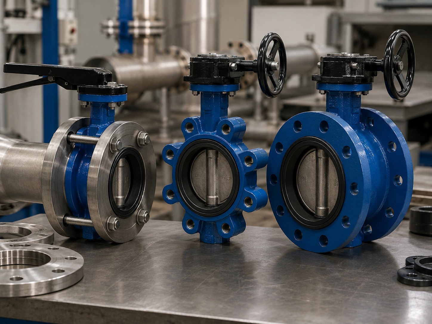
A wafer valve is a butterfly valve when the term refers to wafer-style butterfly construction, so “wafer valve vs butterfly valve” compares a body connection with the larger valve category. The useful decision is wafer vs lug vs double-flanged butterfly valve, followed by the seat, disc geometry, materials, rating, and operator that the service requires.
This terminology causes real specification problems. A buyer may request “a butterfly valve” without defining the body style, while an installer may order “a wafer valve” without checking shutdown needs, flange bore, disc clearance, or sealing direction. Either description leaves critical decisions open.
RUITO’s published industrial butterfly valve range includes wafer, lug, and flanged connections. That range illustrates the correct approach: choose the connection as one part of a complete valve specification, not as a substitute for it.
The Comparison Mixes a Valve Type with a Body Style
Butterfly valve defines the operating principle, while wafer defines how one butterfly-valve body is mounted between pipe flanges. A butterfly valve uses a stem-driven disc that turns approximately 90 degrees to start, stop, or regulate flow. Its body can be wafer, lug, double-flanged, or another end configuration.
This is not merely a naming preference. The American Petroleum Institute’s current standards plan places double-flanged, lug, wafer, and butt-weld end configurations under API Standard 609 for butterfly valves. In other words, wafer and lug describe versions within the butterfly-valve family.
There is one ambiguity to catch early: “wafer valve” can also refer to a wafer check valve. A butterfly valve has a commanded stem connected to a lever, gearbox, or actuator. A wafer check valve normally opens and closes automatically in response to flow and pressure direction. If the component has no quarter-turn operating stem, confirm the valve type before comparing body styles.
Wafer, Lug, and Double-Flanged Bodies Solve Different Problems
Wafer, lug, and double-flanged bodies differ mainly in how they connect to the piping and what that connection permits during maintenance. The table compares the decisions that body style can legitimately answer.
| Decision point | Wafer butterfly valve | Lug butterfly valve | Double-flanged butterfly valve |
|---|---|---|---|
| Pipe connection | Clamped between two flanges with through-bolts or studs | Each flange is fastened separately to threaded or tapped body lugs | Integral valve flanges bolt to the mating pipe flanges |
| Space and weight | Usually the most compact and lightest option | Heavier because the body carries the lugs | Usually the longest and heaviest of the three |
| Normal maintenance boundary | The complete flange-valve-flange section is isolated before removal | One pipe side may be removable while the valve remains attached to the other | Provides a rigid, independently bolted connection on both sides |
| Dead-end service | Do not assume it is permitted | Possible only with a documented model-specific rating | Possible only with a documented model-specific rating |
| Typical selection driver | Low installed weight, tight space, and full-section shutdown access | Sectional maintenance or a specified one-sided pressure condition | Large size, permanent installation, alignment, or structural-load needs |
| Evidence to request | Flange fit, disc clearance, stud details, and gasket instructions | Lug drilling, thread engagement, pressure direction, and dead-end rating | Flange drilling, face-to-face dimension, support loads, and dead-end rating |
The practical difference is not that one body style is universally stronger or more reliable. Wafer is often the efficient choice for a conventional inline valve. Lug earns its added material and cost when independent bolting solves a real maintenance requirement. Double-flanged construction is valuable when the piping layout or valve size needs a more rigid interface.
Let the Shutdown Plan Decide the Body Style
Choose the body style from the planned maintenance boundary, not from appearance or unit price. The question to ask is: what must remain connected, isolated, and pressure-free when this valve or the adjacent equipment is serviced?
Use wafer for full-section shutdowns
Choose wafer when both sides of the line can be isolated, drained, depressurized, and supported before the valve or adjacent pipe is removed. It is especially attractive where installation space, handling weight, and initial cost matter. Its limitation is operational: the through-bolted assembly depends on both pipe flanges, so removing one side changes the joint that holds the valve.
Use lug only with a defined one-sided duty
Choose lug when the maintenance plan requires the valve to remain attached to the upstream flange while downstream pipe or equipment is removed. Then request the allowable dead-end differential pressure, permitted pressure direction, temperature limit, seat-retention arrangement, and required cap screws for the exact model. A lug body name alone does not prove full-pressure dead-end capability.
Use double-flanged for a rigid permanent interface
Choose double-flanged when large size, pipe alignment, structural loads, or a permanent independently bolted connection justify the added weight and face-to-face length. Do not treat “flanged” as automatic proof of higher pressure, bidirectional shutoff, or safe dead-end service; those remain configuration-specific ratings.
Connection style also does not replace an energy-control procedure. For U.S. general industry, OSHA 29 CFR 1910.147 requires hazardous energy to be controlled during servicing, residual energy to be made safe, and isolation to be verified. A rated lug or flanged valve can support the isolation design, but it does not by itself authorize work on a pressurized system.
Verify the Complete Flange-Valve Interface
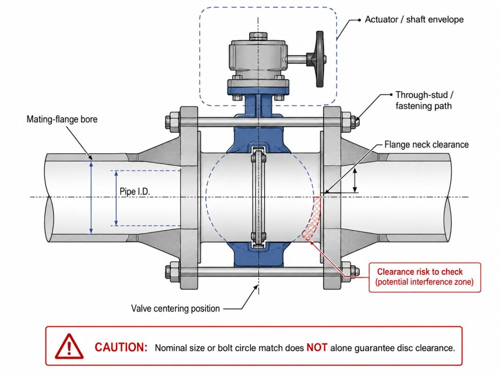
A nominal valve size is not enough to prove that a wafer, lug, or flanged body will fit the line. Approval should cover the complete flange-valve-flange assembly, including the disc’s movement inside the actual pipe bore.
ASME B16.5 defines pressure-temperature ratings, materials, dimensions, tolerances, bolting, gaskets, and joints for the flanges within its scope. It does not prove that a particular butterfly valve matches every flange of the same nominal size. The valve drawing and the piping specification must close that gap.
Before release, check:
- Nominal size, flange standard, pressure class or PN rating, and flange face type.
- Valve face-to-face dimension and available installation gap.
- Mating-flange bore, pipe inside diameter, liner, weld bead, and the valve’s maximum disc sweep.
- Bolt circle, hole quantity and diameter, body-centering features, and neck clearance.
- Through-stud or cap-screw diameter, thread, quantity, installed length, and usable engagement.
- Seat or liner design, flange-surface requirements, and the manufacturer’s gasket instructions.
- Actuator envelope, shaft orientation, access for maintenance, and independent piping support.
For wafer bodies, a disciplined wafer butterfly valve installation check should include a full disc-clearance test before final tightening. A valve can match the bolt circle yet have its open disc strike a small-bore flange, a pipe liner, an internal weld, or a nearby fitting.
Do not add separate flange gaskets by habit. Many resilient-seat wafer designs use the seat faces as the flange seals, and an unapproved gasket can alter compression or operating torque. Other valve designs do require gaskets. The correct answer comes from the installation instructions for the exact valve, seat, and flange face.
Separate Connection Style from Valve Performance
A wafer body does not define the valve’s sealing performance, material compatibility, pressure-temperature limit, or control behavior. Those characteristics must be selected on a second axis after the connection style is chosen.
A complete butterfly valve characteristics review should address at least these independent decisions:
- Disc and seat geometry: concentric, double-offset, or triple-offset construction changes friction, wear, temperature capability, and shutoff behavior.
- Pressure boundary: body rating, seat rating, maximum differential pressure, and any lower dead-end rating are not interchangeable values.
- Shutoff duty: specify unidirectional or bidirectional sealing, the required pressure direction, test standard, test medium, and acceptance criterion.
- Materials: verify body, disc, stem, seat, liner, coating, packing, and fasteners against the exact media, concentration, solids, and temperature range.
- Flow function: an on-off valve and a throttling valve need different Cv, operating-angle, pressure-drop, cavitation, and dynamic-torque checks.
- Operation: define lever, gearbox, pneumatic, hydraulic, or electric actuation, including available power, fail position, cycle rate, closing time, feedback, and worst-case torque.
This two-axis method prevents a common substitution error. Two valves can both be wafer type yet have very different service limits. Conversely, changing from wafer to lug preserves neither the seat design nor the shutoff rating unless the approved data sheet says so.
Write the Order Line So Every Assumption Is Visible
A usable purchase specification must state the service, connection, sealing duty, operation, and required evidence rather than stop at “wafer butterfly valve.” The following format turns the selection into fields that engineering, procurement, the supplier, and the installer can all verify:
[DN/NPS] [wafer/lug/double-flanged] butterfly valve; [flange standard and class/PN]; [concentric/double-offset/triple-offset]; [body, disc, stem, and seat materials]; [unidirectional/bidirectional] shutoff at [maximum differential pressure and direction]; [dead-end duty if required]; [operator and fail position]; tested to [standard and acceptance criterion].
Attach the real operating conditions: fluid and concentration, solids, minimum and maximum temperature, normal and design pressure, maximum differential pressure, minimum and maximum flow, on-off or throttling duty, cycle frequency, installation orientation, and environmental exposure.
Then define the approval evidence. Request a general-arrangement drawing, face-to-face dimension, flange drilling, clear bore and disc-sweep envelope, valve torque data, actuator sizing basis, material certificates, pressure and seat test records, coating data where relevant, and the installation and maintenance manual. If the body is lug type, use a lug butterfly valve bolt chart only to confirm the flange pattern; obtain final cap-screw length and thread engagement from the supplied valve drawing.
If dead-end service is required, place it on the data sheet and purchase order as a separate duty. State the pressure side, maximum differential pressure, temperature, flow direction, and whether downstream pipe removal is part of the operating plan. That wording is far safer than assuming the lug or flanged connection automatically includes the requirement.
Choose the Body Style from the Maintenance Boundary
The correct answer is simple: wafer is usually the efficient inline body, lug is justified by a documented one-sided maintenance or dead-end requirement, and double-flanged construction suits a more rigid permanent interface. None of those choices finishes the valve specification.
Confirm the shutdown plan first, then verify the flange interface, disc clearance, sealing direction, materials, rating, operator, and acceptance documents. If some parameters are still unknown, you can contact RUITO with the media, pressure, temperature, size range, maintenance objective, and project stage you already know; the remaining questions can be resolved during the technical review.
FAQ
Do wafer butterfly valves need separate flange gaskets?
Not always. Many resilient-seat wafer valves use extended seat faces to seal against the mating flanges, so adding separate gaskets may cause excessive compression or high torque. Other constructions require gaskets; follow the exact model’s installation manual and approved flange-face detail.
Can a lug valve replace a wafer valve without piping changes?
Only after a dimensional and bolting review. Confirm face-to-face length, flange drilling, cap-screw requirements, clear bore, disc sweep, neck and actuator clearance, and any change in piping support before approving the replacement.
Does flow direction matter for a wafer butterfly valve?
It can. Some resilient concentric designs seal bidirectionally, while offset or application-specific valves may have a preferred pressure direction. Use the body marking, approved data sheet, and tested shutoff direction for the supplied model.
What drawing should be approved before ordering?
Approve a model-specific general-arrangement drawing. It should show face-to-face length, flange standard and drilling, clear bore, disc sweep, body and shaft dimensions, operator envelope, flow or pressure direction where applicable, and the materials tied to the valve tag or item number.